Patrick, Jeff, Evan
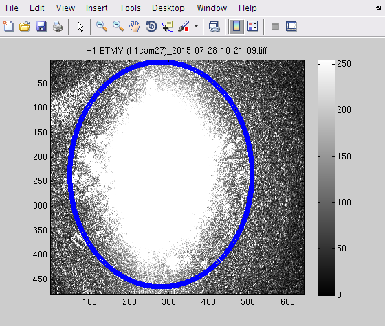
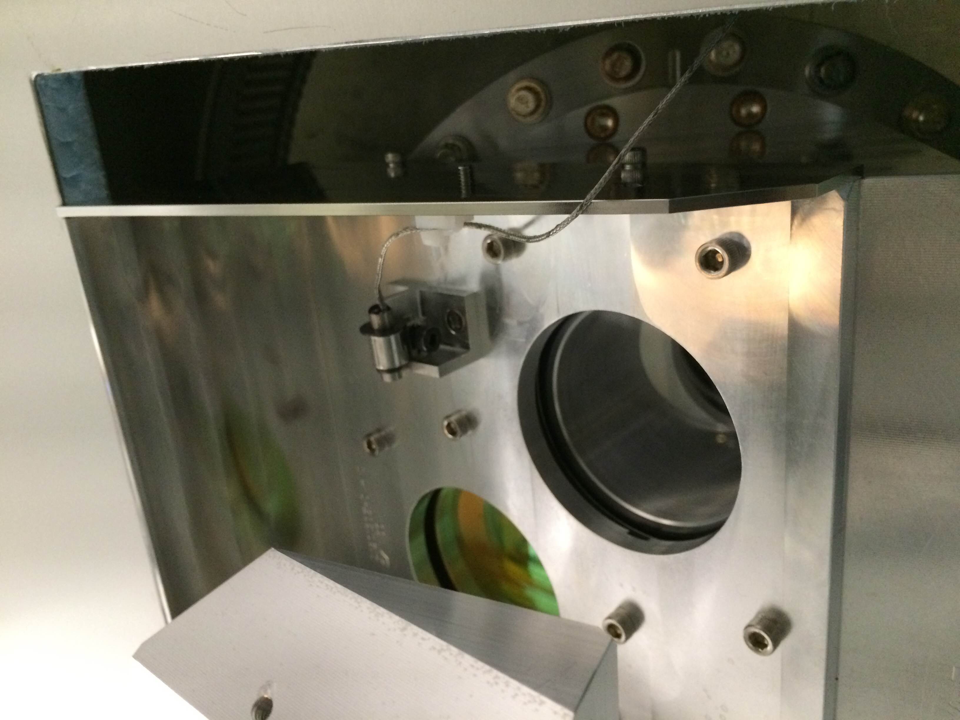
We spent a few minutes cooking the IX compensation plate while trying to make the TCS rotation stage behave.
- To start with, the controller reported the measured angle as 0°. (During the previous TCS tests on Sunday, it was more like 55°.)
- When I asked for a different angle, the controller complained "Status: position warning", and the measured angle didn't change.
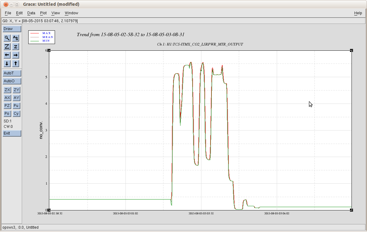
- So we asked it to search for home, which seemed to work. The homing position seems to be around the max power out of the TCS (5 W).
- Then I asked for 50°, but for some reason the measured angle dropped to −7° and then stopped.
- Then I asked for some other angles, but the stage kept rotating to random places.
- Then I searched for home again, and then asked for −50°. This time it seemed to work.
- Then I tuned the requested angle until the power output was 0.12 W.
This was after the Beckhoff chassis was power cycled.
If after the beckhoff chassis is cycled and if you do not first "refind home" then you will find these issues with the rotation stage not knowing what angle to go with as it loses its mind where its at. I cant say I have noticed the waveplate acting up after this step is taken (but maybe it has without me noticing)
Also note that search for home does not take the waveplate to minimum angle necessarily. You should be pressing "go to minimum power". So after a Beckhoff restart, usually here at LLO we search for home first, so that the rotation stage finds its 0 point again, then go to minimum power and then start operating it from there. A known issue all along is that as the waveplate rotates to home it could go through a brief period where it allows maximum power into the IMC or onto the ITM CPs