End-of-Shift Summary: Recovering from Chilean Earthquake(s) barrage is an understatement as there have been close to 20 after-shocks (and a smattering of New Guinea and Alaska to round out the competition), most of significant magnitude. I was able to complete an initial alignment at, around, 03:10UTC and began the locking sequence but never made it past CHECK_IR. At that point the seismograph started to climb again. Fortunately there was no further tripping of systems. Mother Nature is really letting her hair down! ( and having a few). Handing off to Nutsinee.
Activity log:
23:00 IFO locked
23:23 LOCKLOSS Chilean Earthquake 8.4MAG 23:45UTC
23:30 Began damping Seismic systems with Hugh’s tuteledge
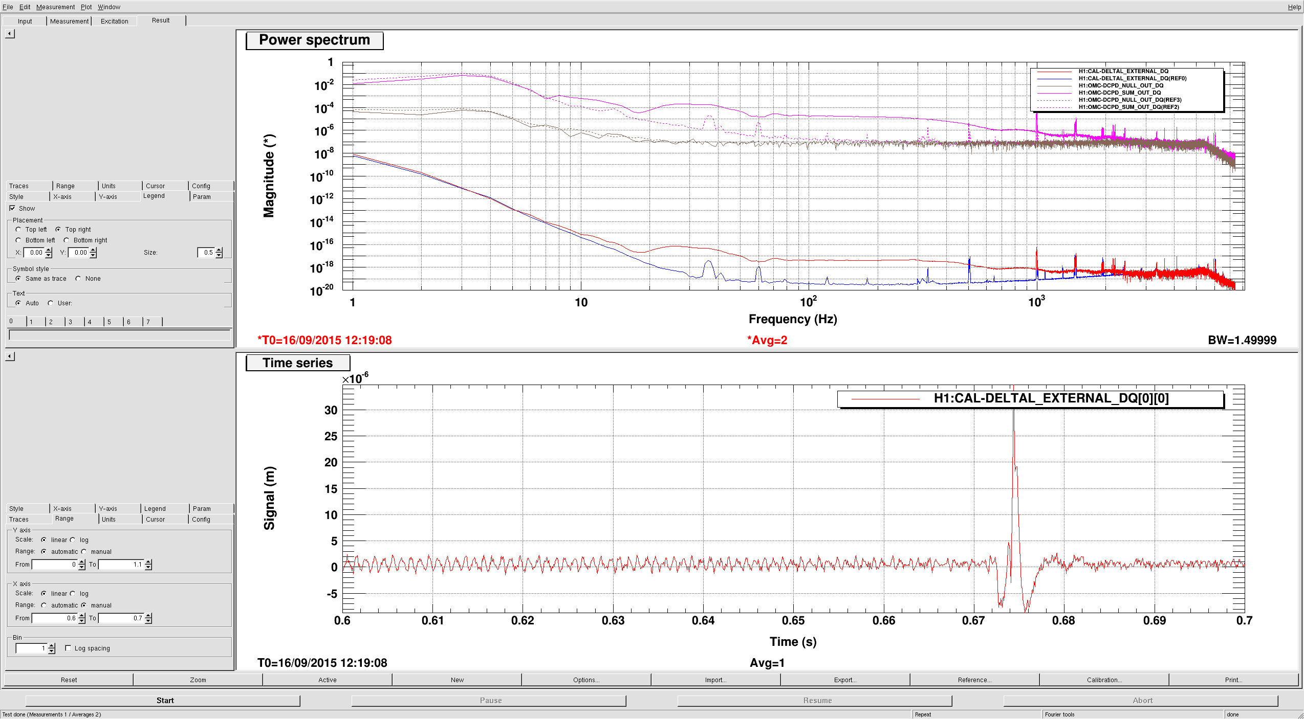
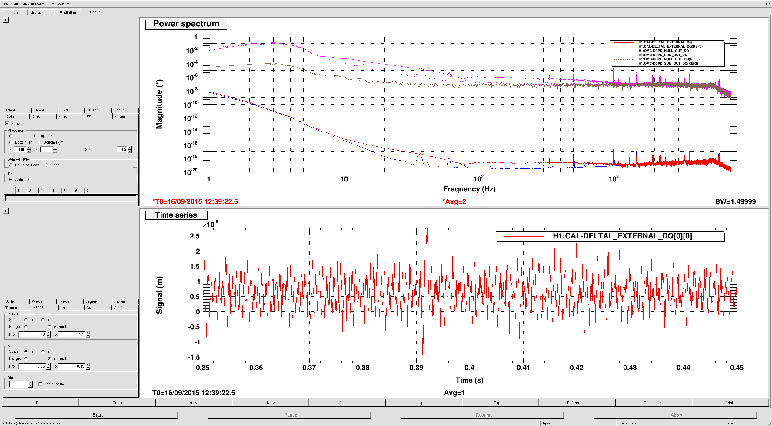
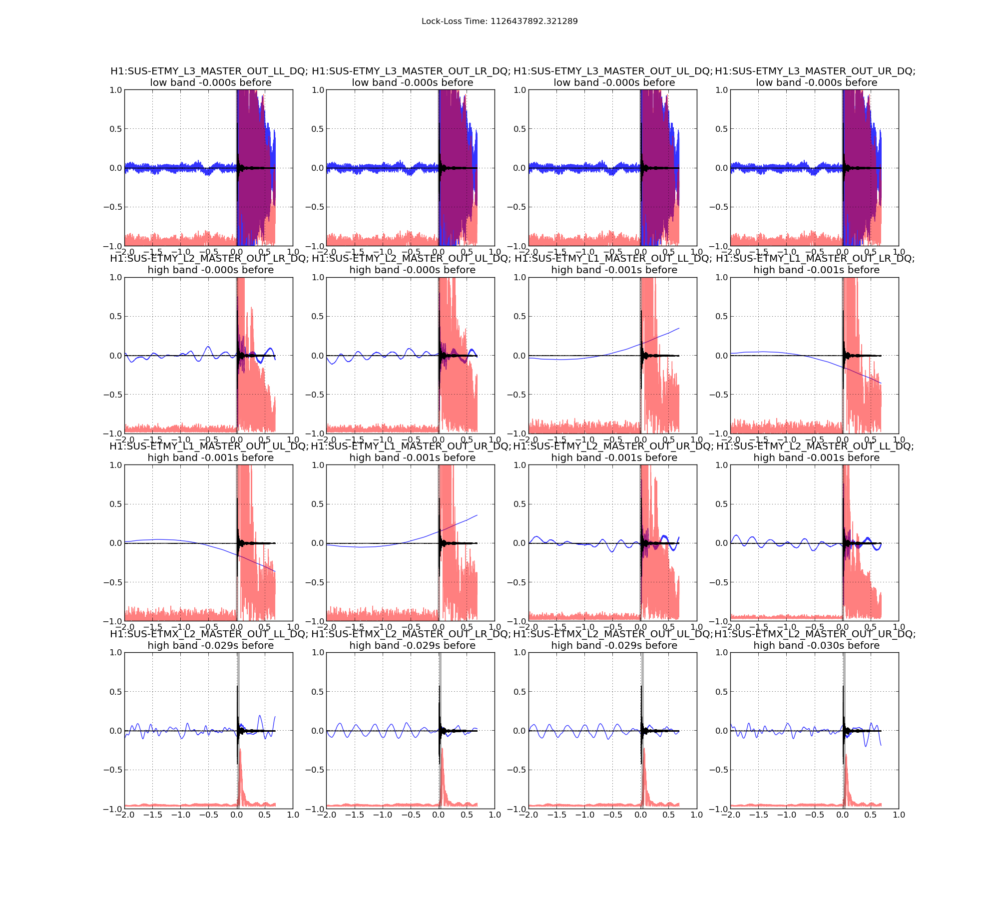
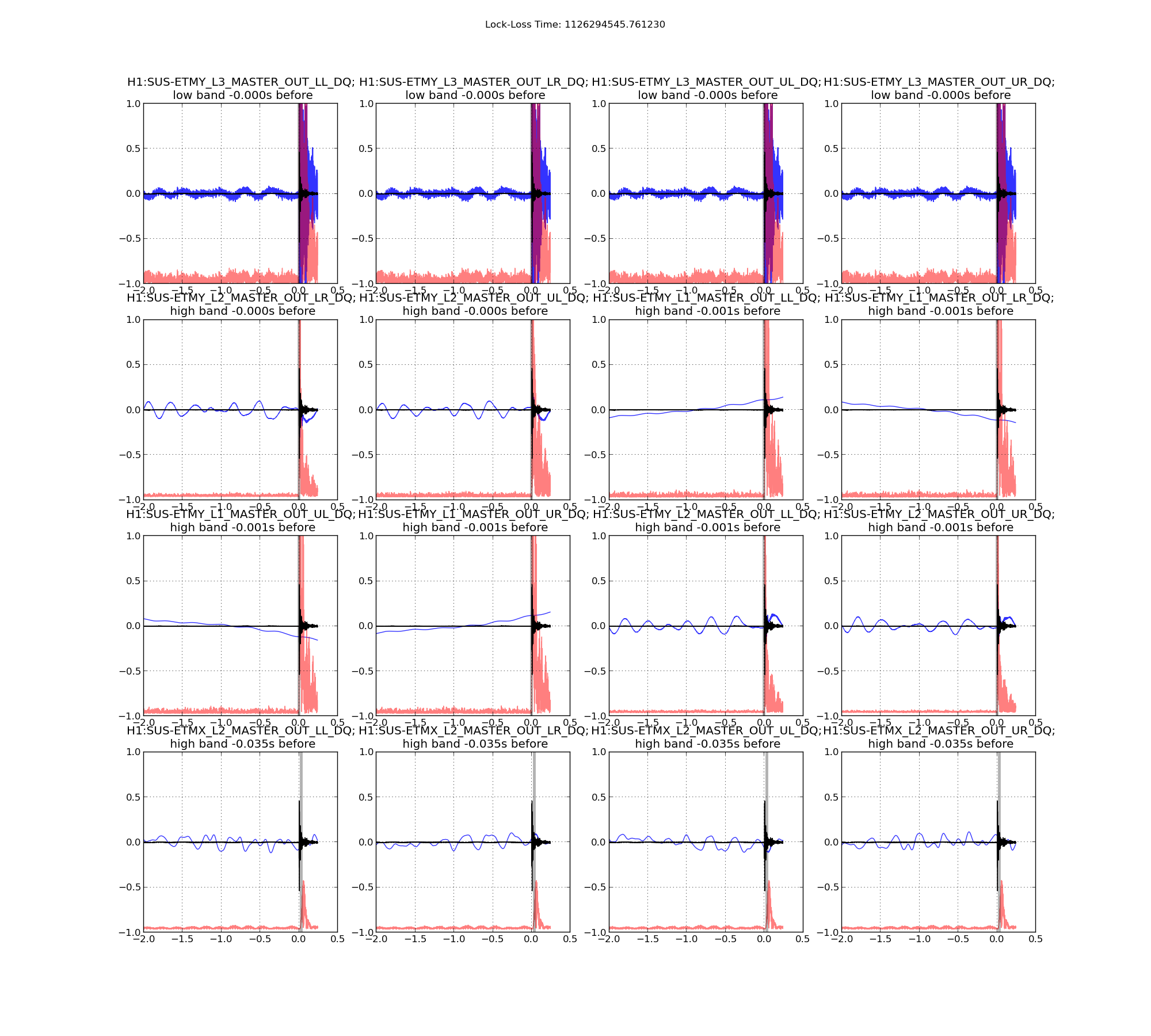
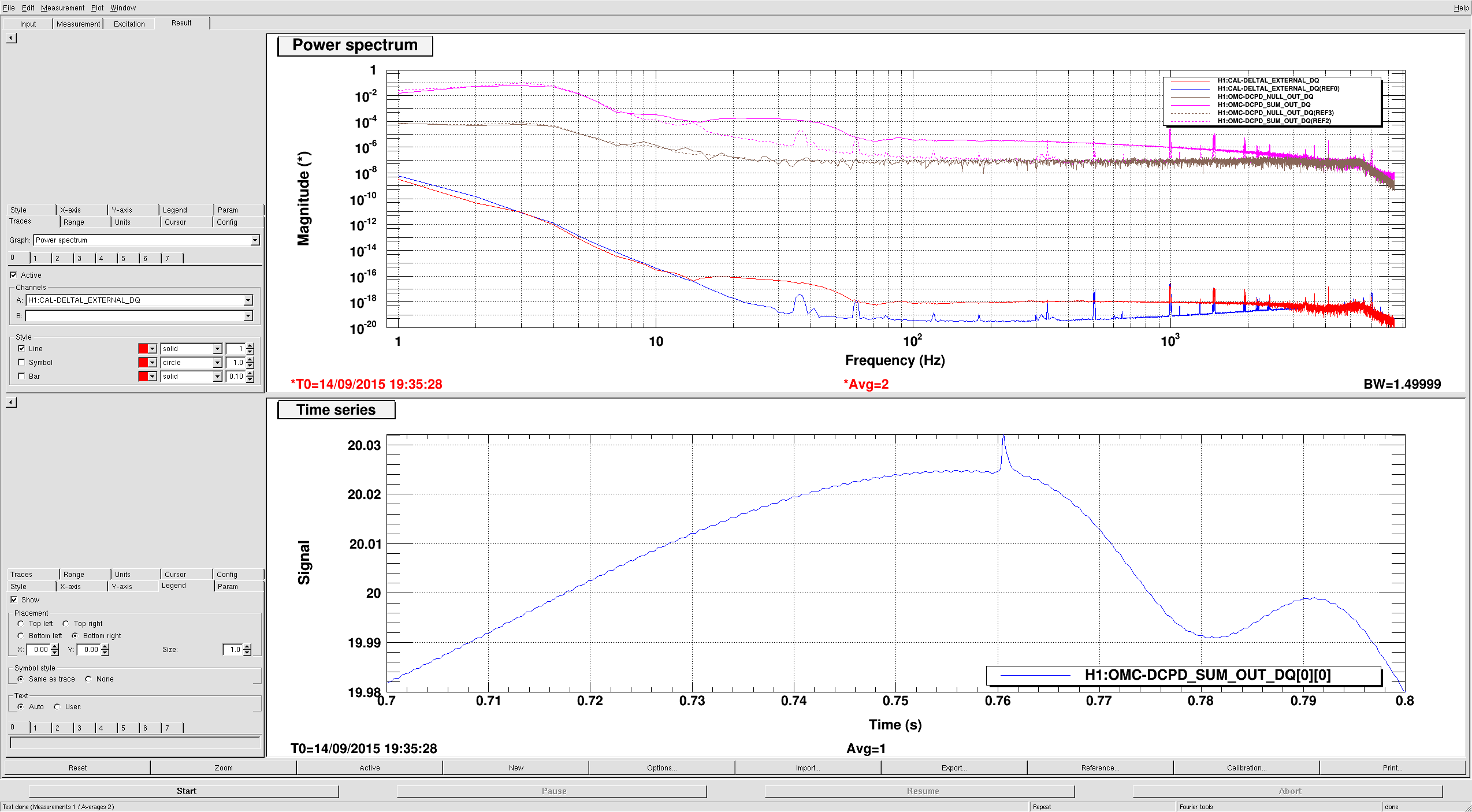
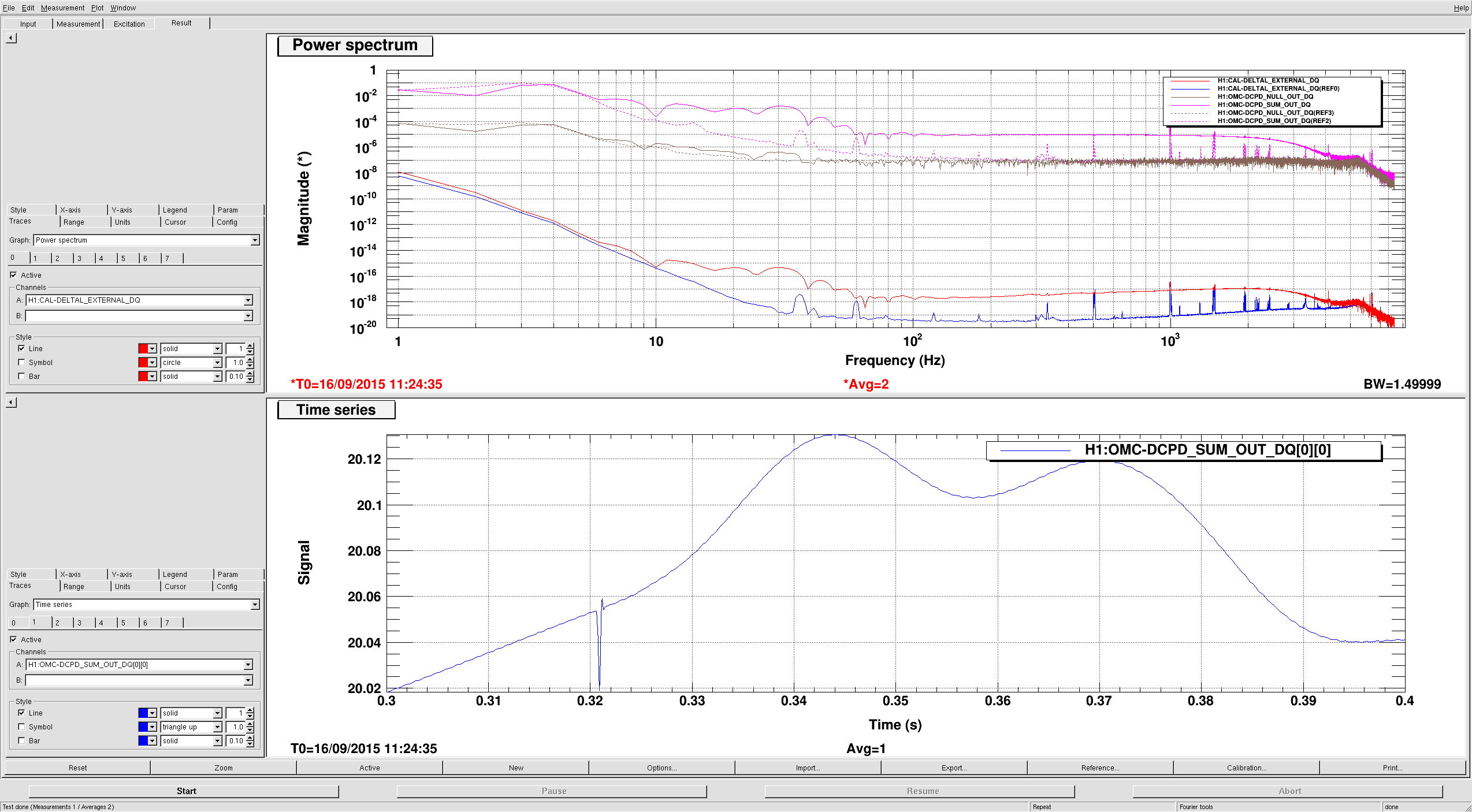
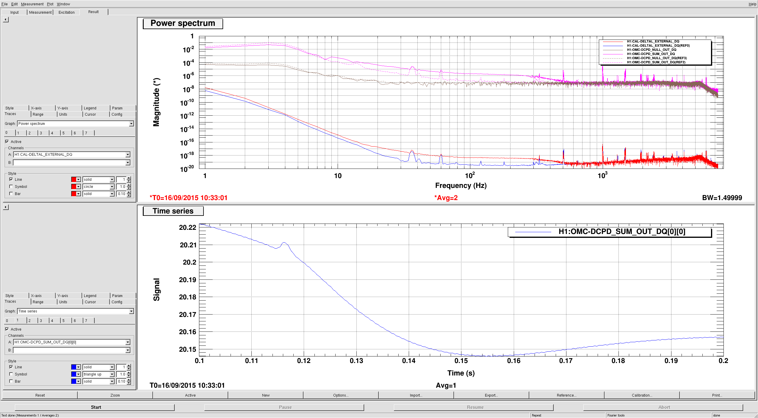
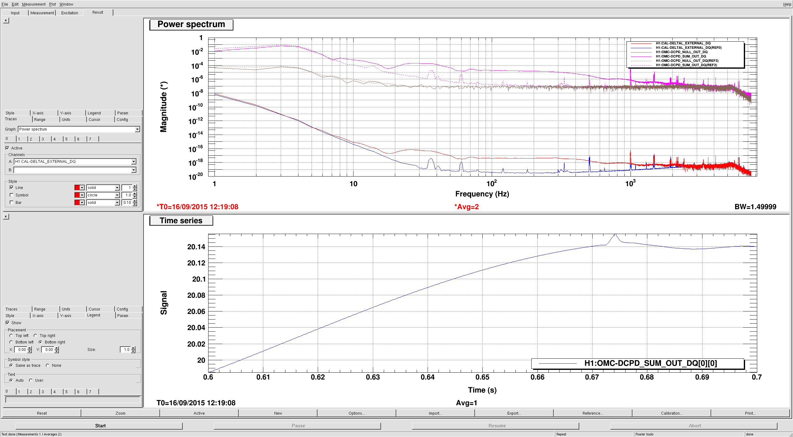
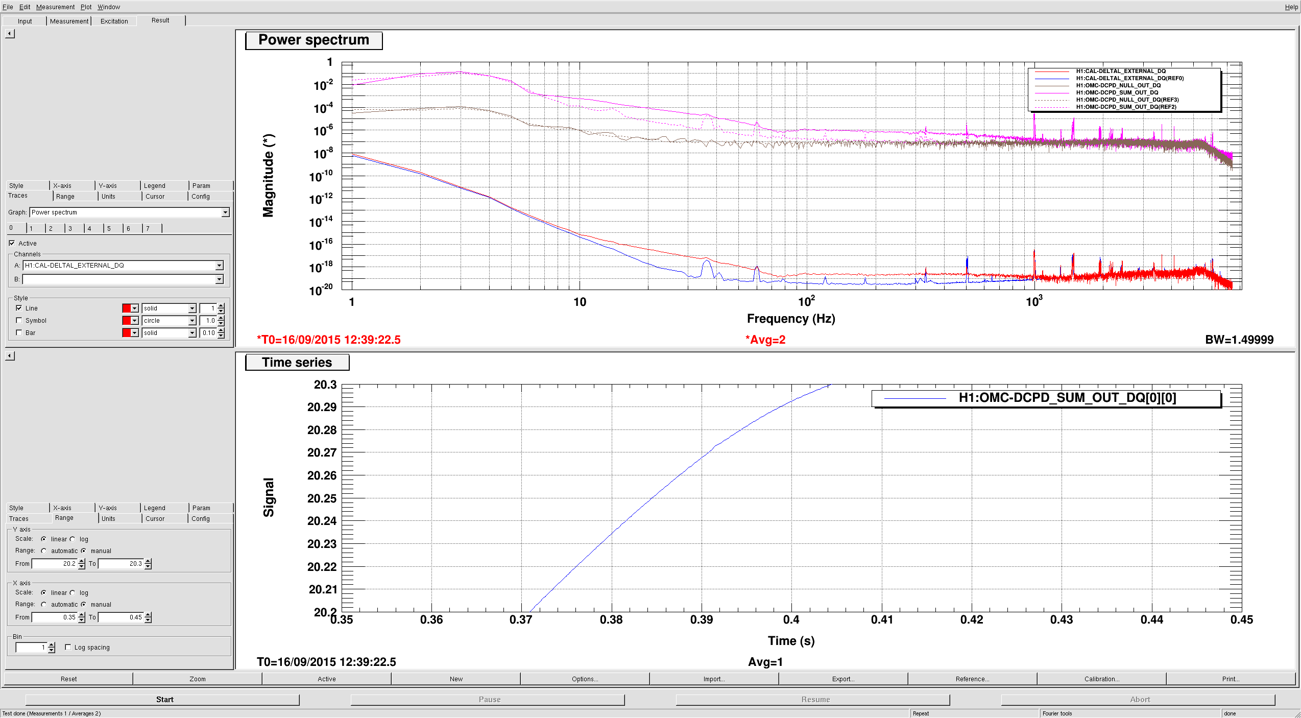
00:32 Jeff Kissel taking advantage of the earthquake break to do some charge measurements
00:45 Darkhan also doing some open loop measurements in this down time.
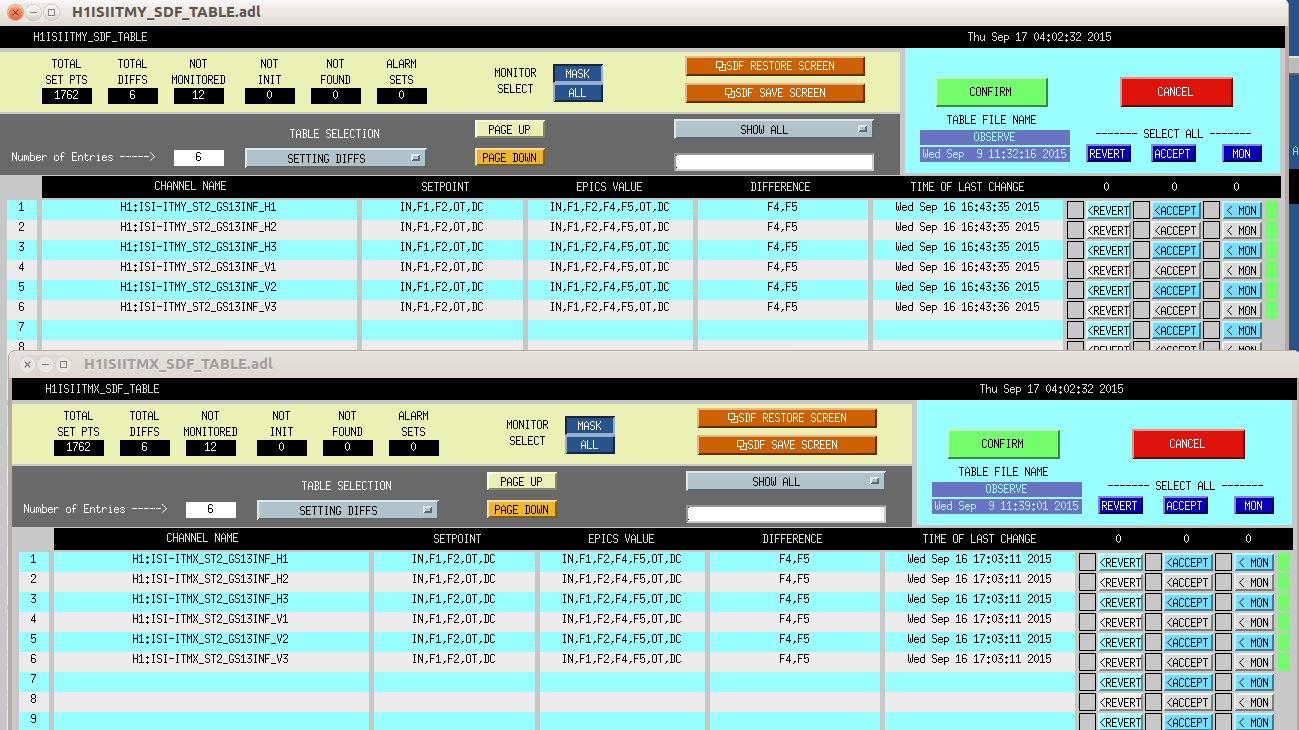
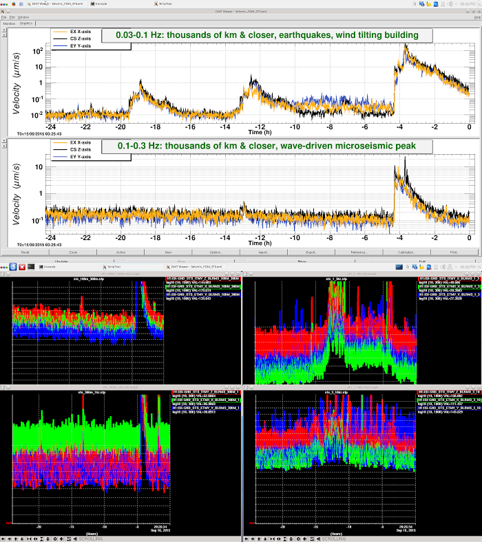
02:05 Attempt to bring back End Station ISIs seems succesful. GS 13s back to high gain. Seismic graph is showing 3µ/S.
02:09 Ditto for ITMs
02:10 Begin bringing up Input and Output HAM SEI.
02:15 Kissel brought ESDs back and restored ETM alignment.
02:31 All SEI back to nominal isolated states. GS13 gains switched back to HIGH.
02:34 IMC re-locked. Looks like the ground motion is still too great to begin aligning arms.
03:10 started initial alignment. Waited at DarkMich to watch excessive ground motion
03:34 GRB alarm. https://gracedb.ligo.org/events/view/E184908 .
03:58 began locking sequence. ot as far as CHECK_IR...too much ground motion and then more earthquakes.
04:00 switched Observation mode to Environmental
05:38 Ground motion starting to drop below 1µm/s. Attempt at locking DRMI shows way too much motion.


Lockloss 13:15 UTC. I'm not sure if we lost lock due to a single 5.3M earthquake in Chile or two consecutive 5.3M earthquakes that happened just 5 minutes apart from each other. Requested ISC_LOCK to DOWN and waiting for the earthquake to pass....
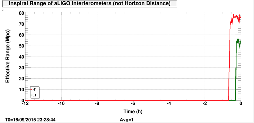
Observing again at 74Mpc.