rich.abbott@LIGO.ORG - posted 15:45, Saturday 29 August 2015 (21010)
Ambient RF Field Measurements
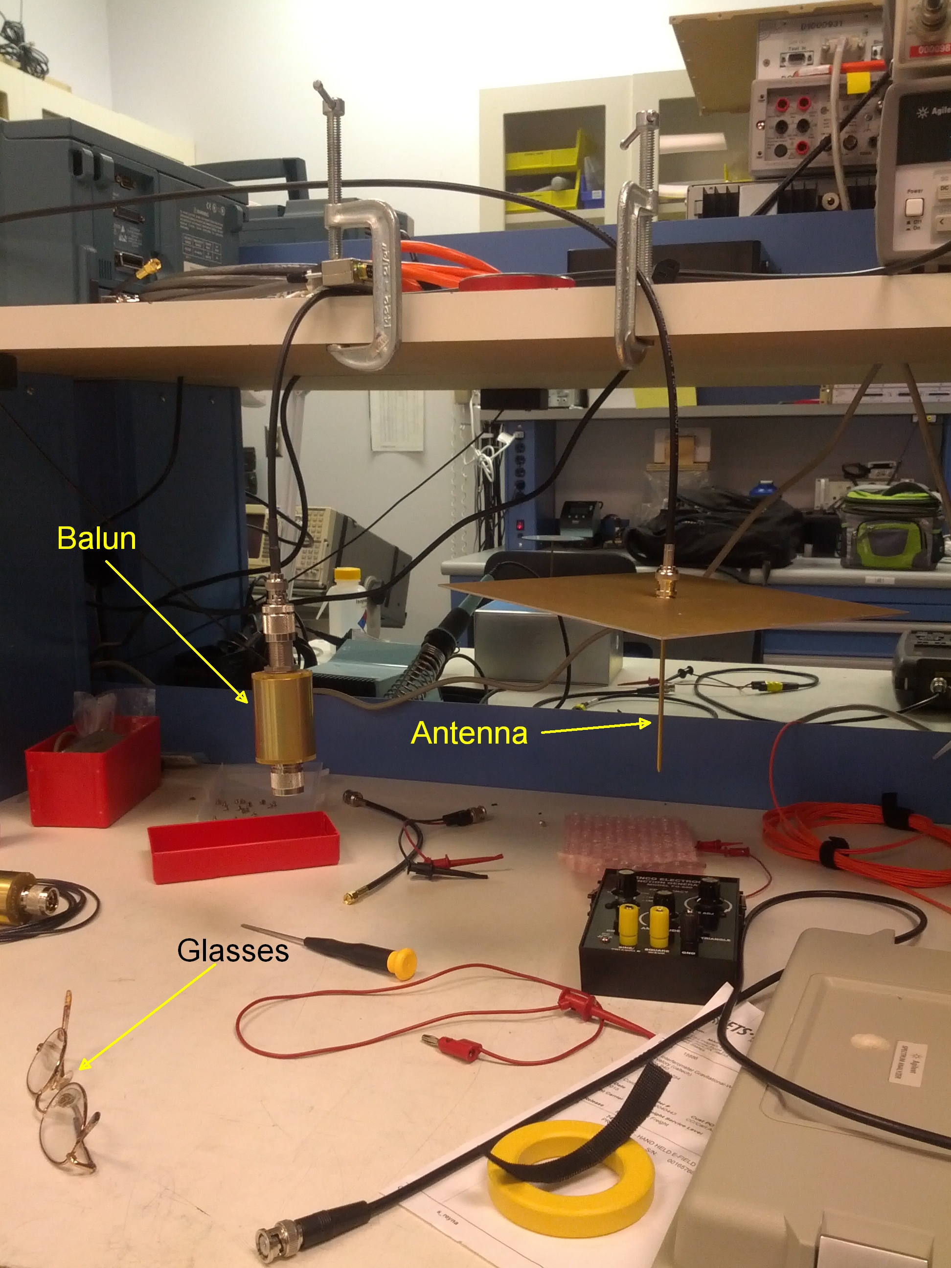
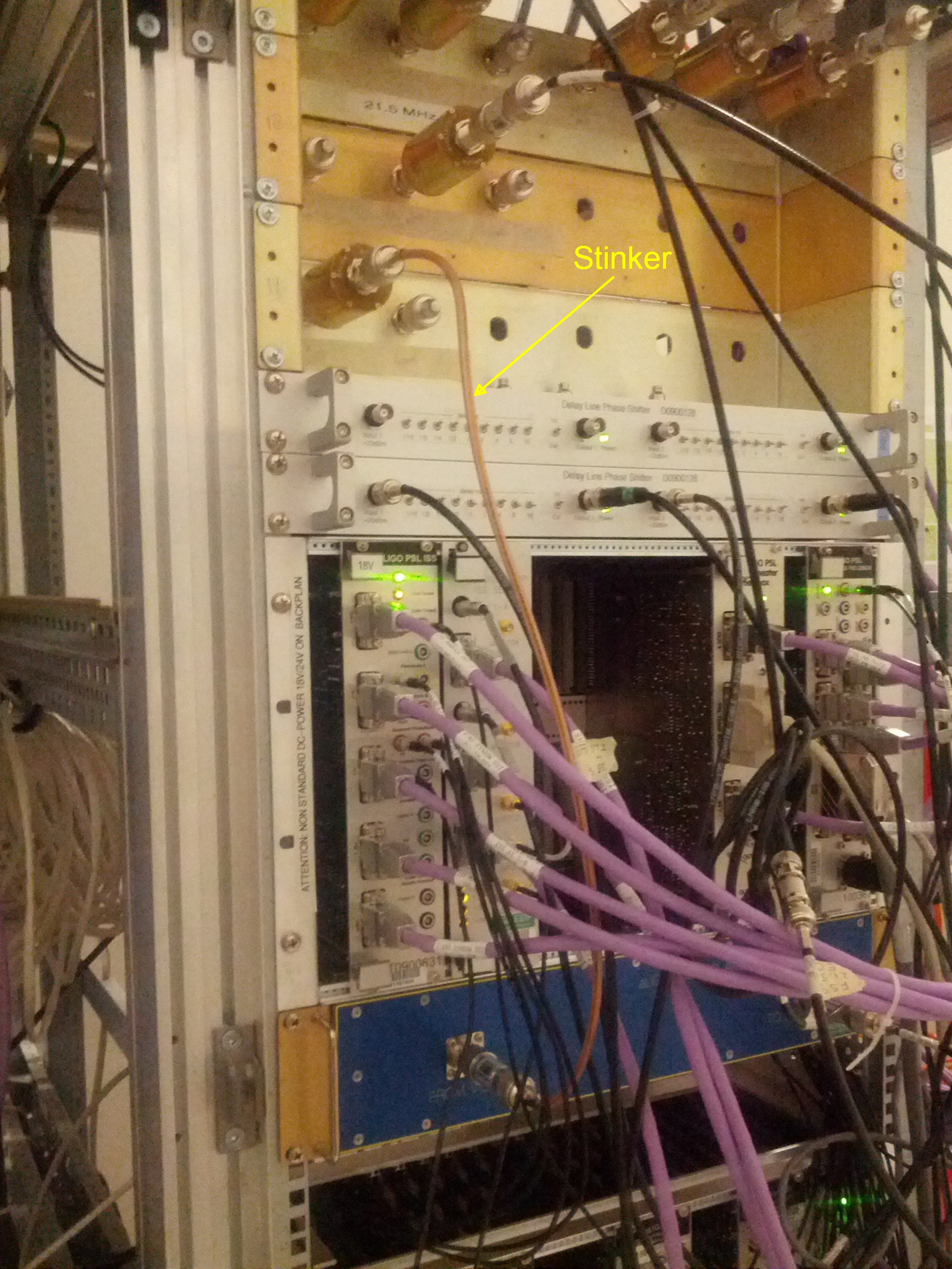
Conclusion:
For those liking a quick summary, there isn't a significant difference between the RF field levels at LHO and LLO

Overview:
A series of measurements were taken with the goal of comparing the ambient RF fields at LHO to those recently measured at LLO by Patrick Meyers and Rai Weiss.  The LLO measurements focused on the RF fields in the vicinity of ISC Rack C4 in the control equipment room (CER).  Nearly 200 separate readings were taken.

Method:
A predominantly magnetic field probe was sent from LLO to LHO such that the measurements be a fair comparison.  The probe consists of copper wire wound around a small RF ferrite core similar to those used in the iLIGO WFS.  A probe such as this has a directionality depending on the relative angle of the sensing coil to the driving magnetic field.  At each point of measurement, the maximum RF level was recorded by choosing the optimum angle to hold the sense coil.  There is a large (up to 10dB or more) error bar in this type of near-field measurement as movements of an inch or so can greatly influence the measured value of RF.  Only in the far-field, in the absence of sources of reflections, does it become more textbook in its response.

In addition to the magnetic field probe Rai made, I made two matched probes (one was sent to LLO prior to my trip as a basis for future comparisons).  My probes are simple electric field antennae consisting of a 10cm monopole mounted on a square aluminum ground plate measuring 20cm on each side.  The ground plate serves to lessen the proximity effect of nearby objects (hands included).  I used this rudimentary probe to establish an approximate maximum RF field level at chest height about 3 feet from the front of a rack (CER and LVEA) for various frequencies of interest.

The LLO study found that the largest RF fields in the CER are associated with the three VCOs used in the LVEA (ALS-DIFF, ALS-COM, and PSL).  This result holds true for LHO.  The readings make no attempt to catalog the magnitude of each individual peak, instead the largest one was recorded for a given physical location.

Results:
The full results including the 200 or so power readings are being written into a separate document.  Summary results only are presented here.

1.  CER first and second harmonics of the VCOs - RF fields measured with Rai's magnetic field probe range from -60 to -40 dBm in and around the spigots of the RF patch panels and chassis mounted RF units for both the first and second harmonics of the drive frequency (nominally 79.4MHz fundamental).  Maximum RF readings tend to congregate around the baluns that are used to break low frequency ground loops.

2.  A survey using the 10cm electric field probe at chest height, 3 feet from the front of the ISC-C4 rack shows the following typical levels:
VCO fundamental frequency - -68dBm
9.1MHz - < instrument noise floor (-105dBm)
18.2MHz - -99dBm
27.3MHz - -90dBm
36.4MHz - -84dBm
45.5MHz - -78dBm
80MHz (exact, not VCO frequency) -80dBm

3.  A survey using the 10cm electric field probe at chest height, 3 feet from the front of the field racks, ISC R1 and PSL R1 show:
PSL VCO 1st and 2nd harmonic - -60dBm/-57dBm measured in front of PSL-R1, -69dBm fundamental in front of ISC-R1 (the other two VCOs are 10 to 20dB down).  Noted -50dBm 2nd harmonic of ALS DIFF VCO in front of ISC-R1.  The only other signals of any size are the PSL 21.5MHz and 35.5MHz (for FSS and PMC locking).  These PSL frequencies are ~-80dBm everywhere in front of the whole row of racks (ISC to PSL).

4.  Using Rai's magnetic field probe, a signal level of up to -28dBm can be seen emanating from a leaky cable (see attached photo) coupling the PSL VCO to the PSL VCO Amplifier (D1201423) on the front of the PSL-R1 rack.  The radiation is partly due to a low quality braided cable (Pasternak Inc.)and partly due to a balun that is probably not needed anyway as the cable run it serves is only ~10feet.

An isolated test was performed on the RF baluns (see attached photo) commonly encountered in the distribution system.  The electric field antenna was positioned (see attached photo) about 1 foot away from the balun under test.  Adding the balun to the end of the cable increases the received RF power by a factor of ~1000.  There is a provision in each balun to include some capacitors (not included in our deployment).  Among other functions, these capacitors provide an RF ground for the metal body of the balun.  Without this ground, the internal wires (not very RF-ish, but probably OK) are free to radiate.  Adding the capacitors to a balun caused the observed radiation to drop to the background of the measurement equal to the no-balun case.  It is not a pill to be taken lightly, as this will no doubt change the phase of signals receiving this "fix".  Remember, as of now, there's no smoking gun at LHO pointing to a problem with radiated RF.  However, devices that can couple out also tend to couple in, so it offers a path for environmentally modulated RF to reenter and sum with the RF on a cable.

A test device consisting of a small handheld PLL with internal FM (100Hz or so) could be built such that it would be locked to a particular LIGO RF distribution system frequency and provide a small transmitting antenna.  The FM modulated signal could then be probed around to see if any part of the demodulation components are particularly vulnerable (broken shields, loose connectors, etc.) by observing the demodulated signal perhaps while the IFOs are locked.
Images attached to this report