Summary
EPICS values used for calculation of DARM time-varying parameters (DCC T1500377) in GDS pipeline and with PCALMON data were updated on 10-Sep-2015, 01:03:38 PDT (10-Sep-2015, 08:03:38 UTC) using H1 DARM model for ER8/O1. We will analyze DARM time-varying parameters (sometimes generalized as "kappas") calculated in GDS pipeline in GDS frames from nominal low-noise lock stretches after this change.
Previously values written in these EPICS records were calculated based on ER7 model (see LHO alog 20452), now we used ER8/O1 model with parameter file "H1DARMparams_1124954397.m", the summary of this param file residuals were given in LHO alog 21318. There is an additional phase of 136.7 degrees that was fudged into H1:CAL-CS_TDEP_REF_INVA_CLGRATIO_TST_(REAL|IMAG) that should provide kappa_tst with a reasonable phase value (ideally the phase of the kappa_tst should be 0), this was done so that we can test overall performance of GDS pipeline when calculating kappas.
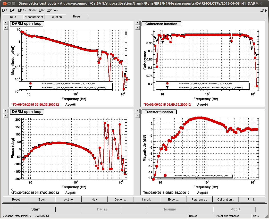
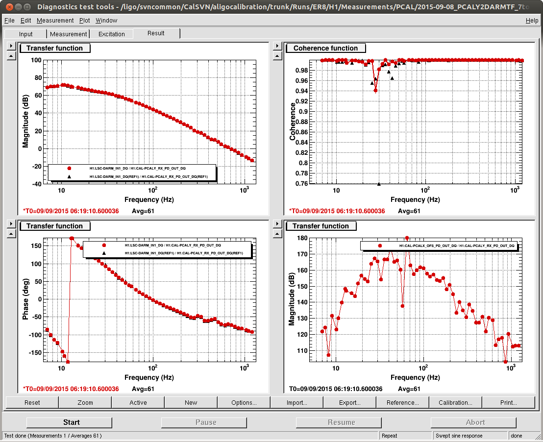
These are not the final values for ER8/O1, currently H1 DARM OLGTF model is under testing using different DARM OLGTF and PCAL2DARMTF measurements and possibly will go through minor adjustments.
New values were accepted in SDF_OVERVIEW (however some of the values still does show up in "diffs", that's because SDF_OVERVIEW cannot handle very small values).
Details
Earlier we had a hard time getting reasonable values for kappas, in Maddie's GDS code as well as recent Greg Mendell and Sudarshan's Matlab code using PCALMON data (see LHO alog 21102). One of the reasons why calculations wouldn't fully agree with actual parameters was that EPICS records had values calculated from ER7 model, which we know is not up to date anymore. But I belive that even after we got a fairly good approximated ER8 model there's probably something missing in EPICS actuation coefficient for x_{tst} calibration line. We're still investigating the source of this discrepancy.
The script that extracts values needed for calculation of kappas from DARM OLGTF model was committed to calibration SVN:
CalSVN/aligocalibration/trunk/Runs/ER8/H1/Scripts/CAL_EPICS/writeER8model_TDEP_EPICS.m
Output files (raw epics values and more verbose log) were committed to the same directory, detailed log is also attached to this alog.
The EPICS values correspond to the model file and the parameter file in calibration SVN at rev. 1374:
CalSVN/aligocalibration/trunk/Runs/ER8/H1/Scripts/DARMOLGTFs/H1DARMOLGTFmodel_ER8.m
CalSVN/aligocalibration/trunk/Runs/ER8/H1/Scripts/DARMOLGTFs/H1DARMparams_1124954397.m