Lock Loss right after PRM saturation - lock loss plot shows an issue in SRCL came first, then PRCL responded, then lock loss
- plot attached shows PRM _M3_LOCK_L_OUTPUT
--- signal changes directions at 17:46:14UTC
--- exceeds it's normal range at 17:46:17UTC
--- abrupt change of the signal at 17:46:22UTC
--- signal exceeds it's normal range (negative) at 17:46:25UTC, Lock Loss
Relocked:
- didn't make it through RF_DARM
Relocked:
- didn't make it through RF_DARM, and I tried to diagnose it, but couldn't, so put the IFO Mode to "unknown,"
Guardian Code issue, corrected:
- Sheila arrived and she diagnosed the problem - Guardian code was waiting for OMC_LOCK to be in "ready to hand off" but OMC wasn't ready.
- Sheila corrected the code so now it only looks at the two arms to see if they are ready.
LSC_LOCK was waiting for OMC to be ready, but OMC wasn't ready, so we cleared that and tried to go on t DARM_WFS and the IFO made some progress but then lost lock.
Relocked
- lost lock at DARM_WFS again - reason unknown.
ETMX Coil issue, corrected:
- after lock loss, ETMX coils died, Sheila went to EX to fix.
Back in Observing/Undisturbed Mode:
- ETMX fixed, relocking went well, and as of 20:36UTC Obs/Und Mode bit set.
NOTE: on the observatory mode screen
I used the UNKNOWN mode for locking issues (since the cause was unknown to me) and for the ETMX fix (because Corrective Maintenance just didn't seem to fit what was an equipment failure).
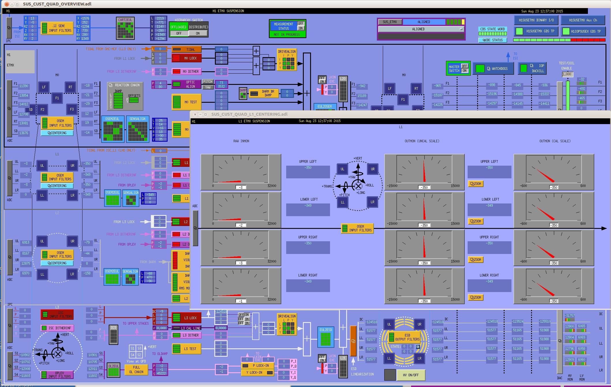


ETMX coils didn't actually die... it was the PUM driver, and it was reset...
Repairs planned for Tuesday Maintenance.