Kiwamu recently found, while trying to to use suspension model to calibrate Pcal, that the use of IIR filter in the front-end results in distortion of the filter response from its actual intended response. (G1501013).
We decided to check all the whitening filters that are use in CAL-CS model to confirm (check) if we see similar effect. The following filters were analyzed:
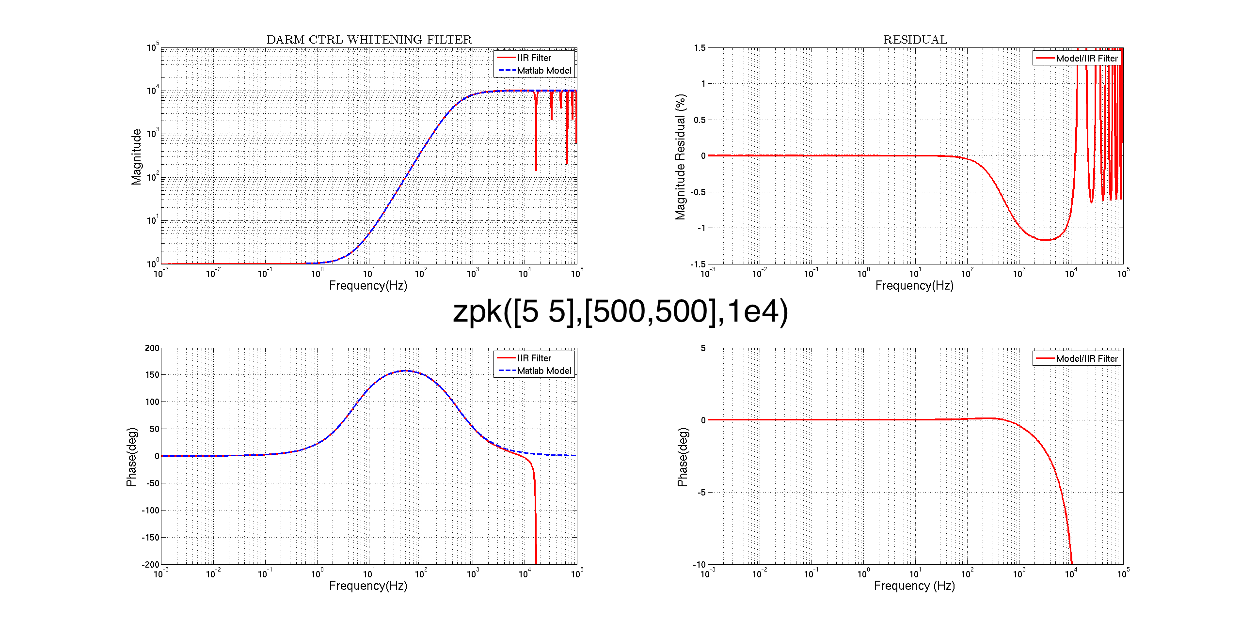
CAL-DARM_CTRL_WHITEN
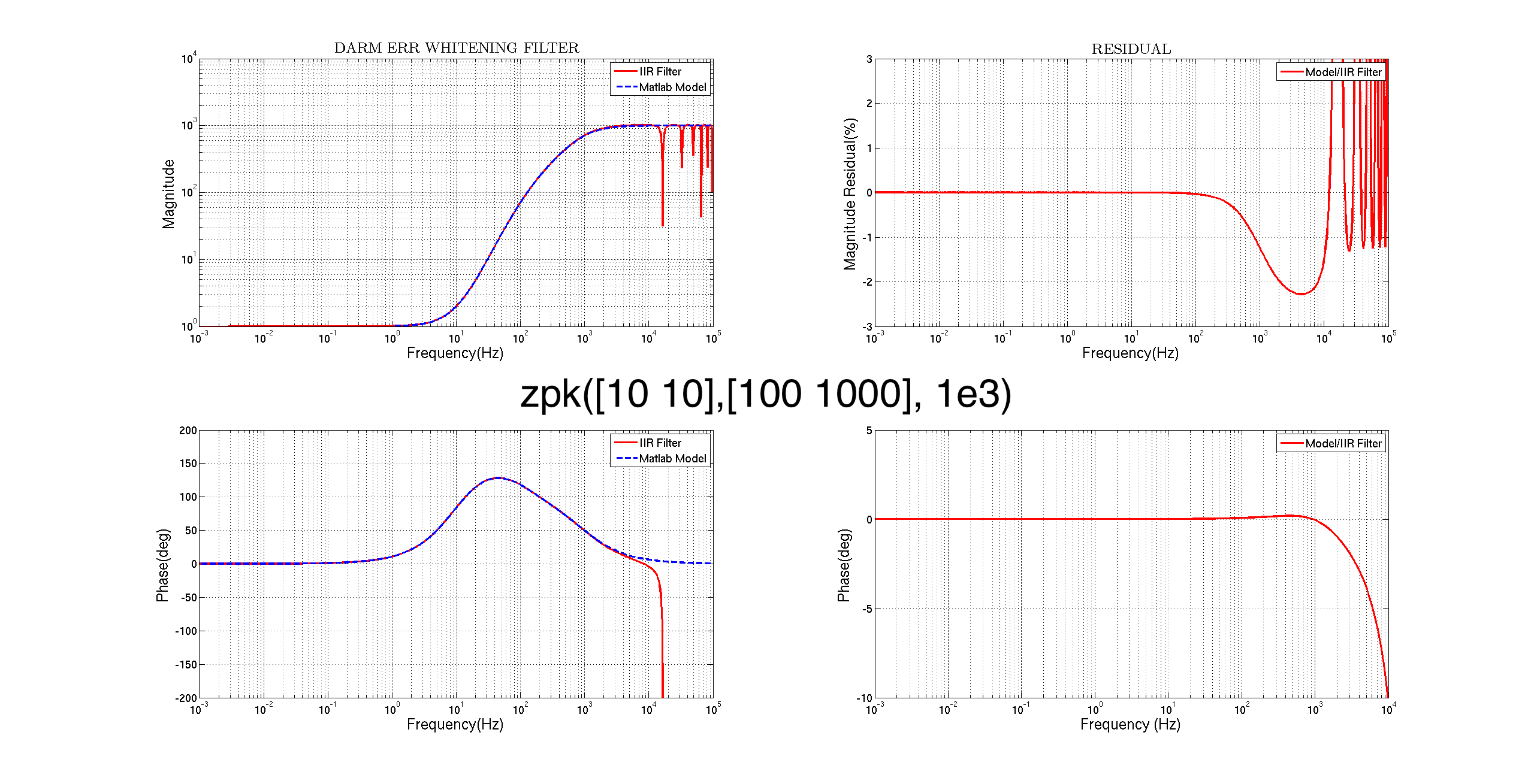
CAL-DARM_ERR_WHITEN
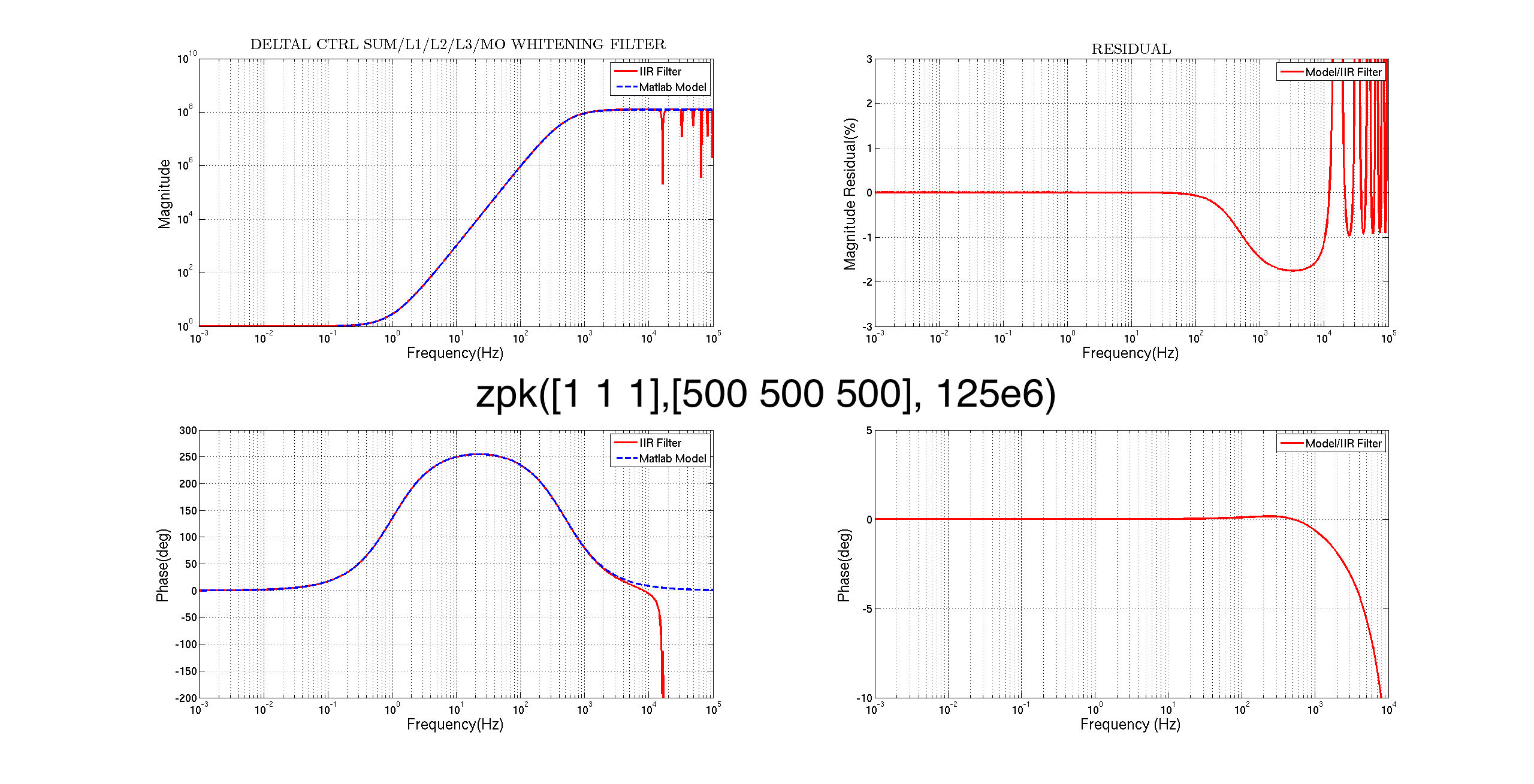
CAL-CS_DARM_DEALTAL_CTRL_SUM(L1/L2/L3/M0)
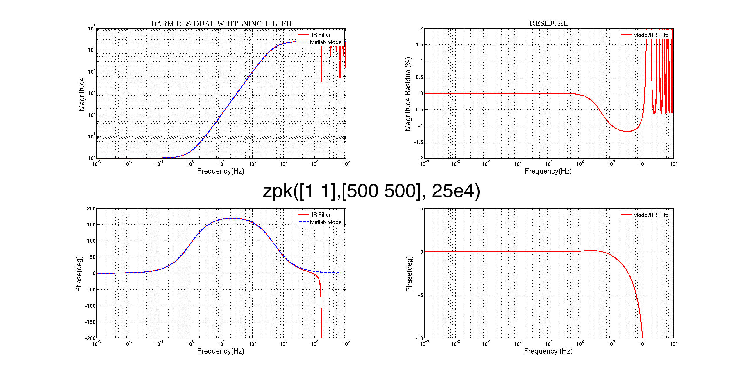
CAL-CS_DARM_RESIDUAL_WHITEN
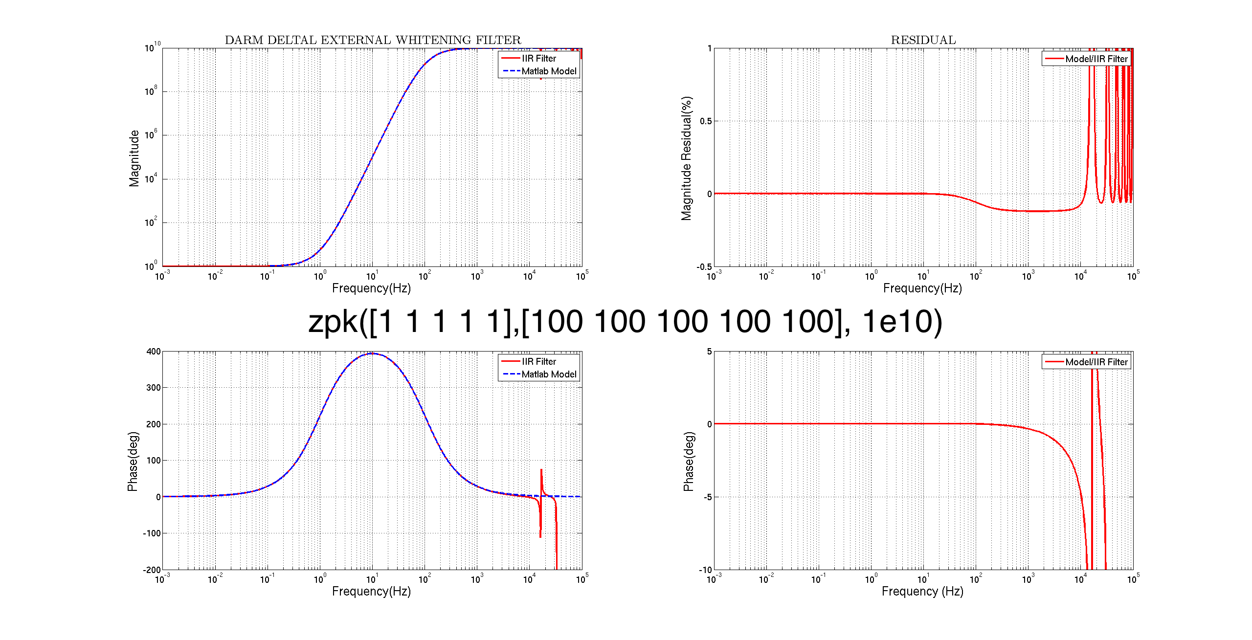
CAL-CS_DARM_DELTAL_EXTERNAL_WHITEN
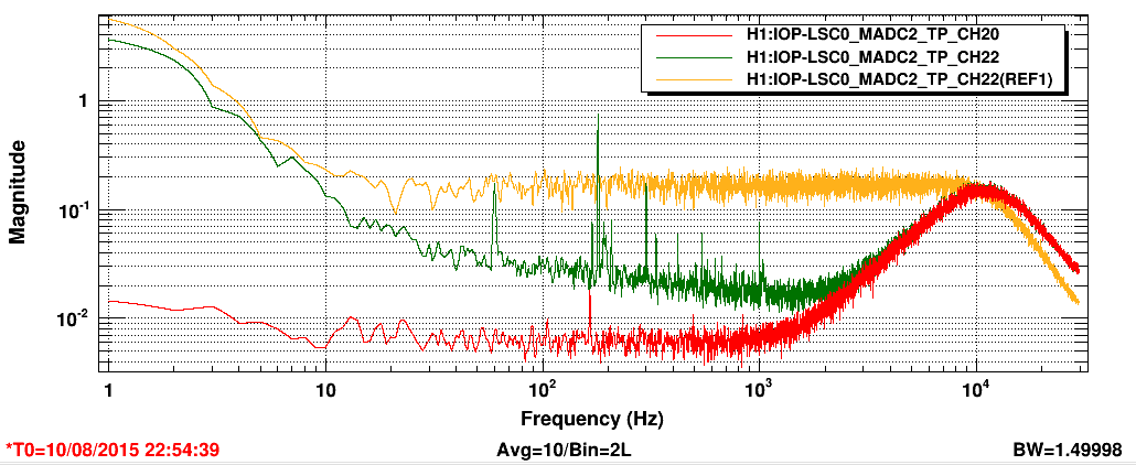
The frequency response of these filters deviate from the model by about 2.5% at its max in amplitude and about 8 degrees in phase (at around 5 KHz). Some filters are severe than the other but they produce this effect nonetheless.
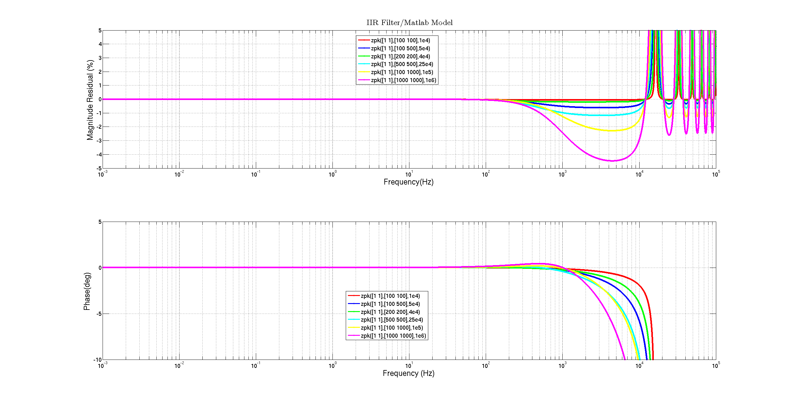
I varied a pair of pole frequencies, keeping two zeros at 1 Hz, to see what the effect looks like. From the last plot, we can see that the distortion is more severe if the pole frequencies are higher.