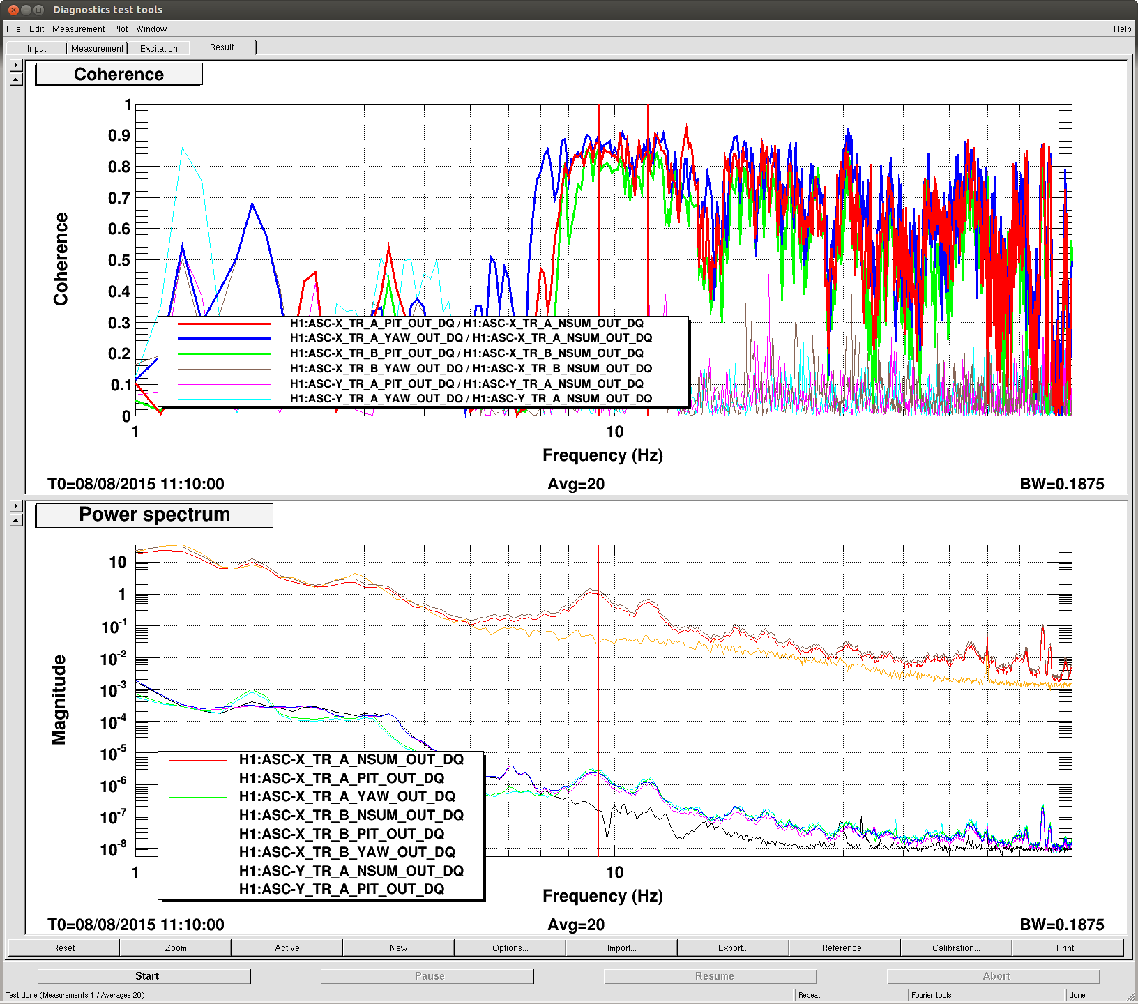
First attachment: Coherences are huge berween TMSX IR QPD SUM, PIT and YAW for 100>f>8Hz in full lock. So many peaks. These appear only when the beam is on QPD.
TMSY QPDs, though not featureless, don't show much coherence and the noise is almost featureless for f>8Hz.
Though X QPDB YAW doesn't show coherence with SUM in this specific plot, this is not always the case (at other times other DOFs loose coherence). Seems like this is dependent on either IFO alignment or TMSX alignment or both.
IN1 of each segment is about 10k counts maximumin full lock, far from saturation.
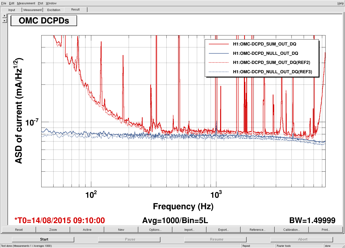
SUM bump at around 9Hz is about 10^-5 RiN/sqrtHz.
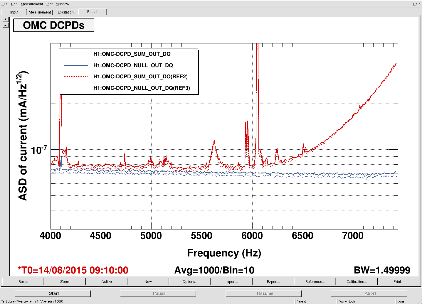
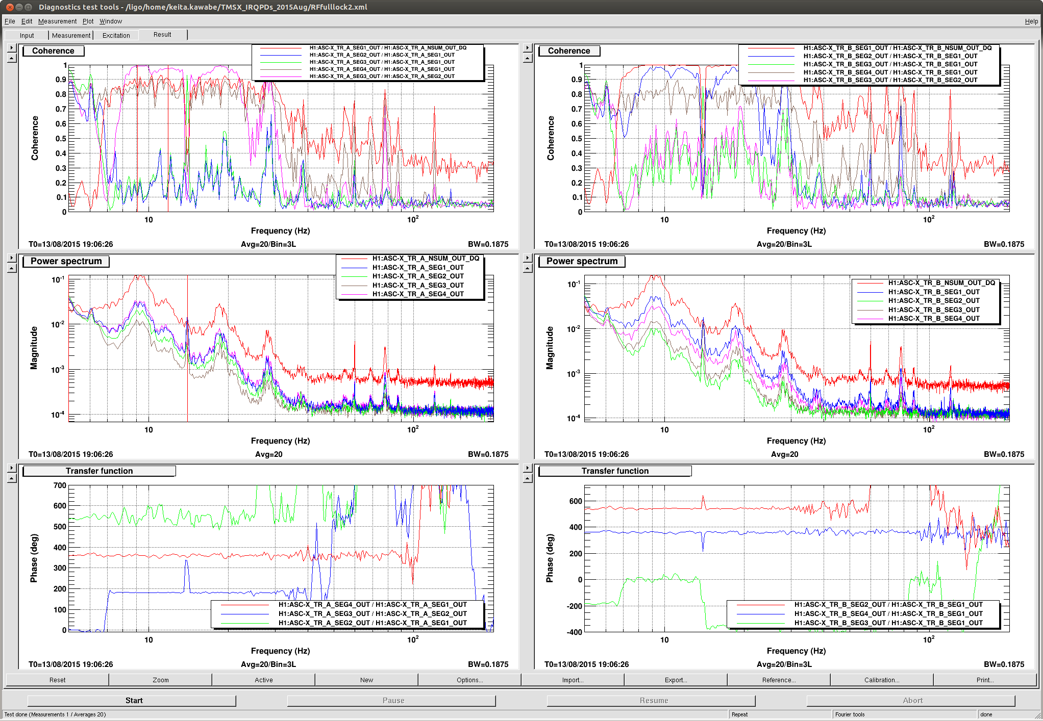
Second attachment: All segments have the same structures. (16Hz peak is probably the roll mode.)
This is in RF full lock, 2.2W, and the peaks look different from the first attachment (e.g. 12Hz bump is a lot smaller relative to 9Hz bump, there are 2nd, 3rd and maybe 4th harmonics of 9Hz bump).
The 9Hz bump is O(10^-5) RIN/sqrtHz again.
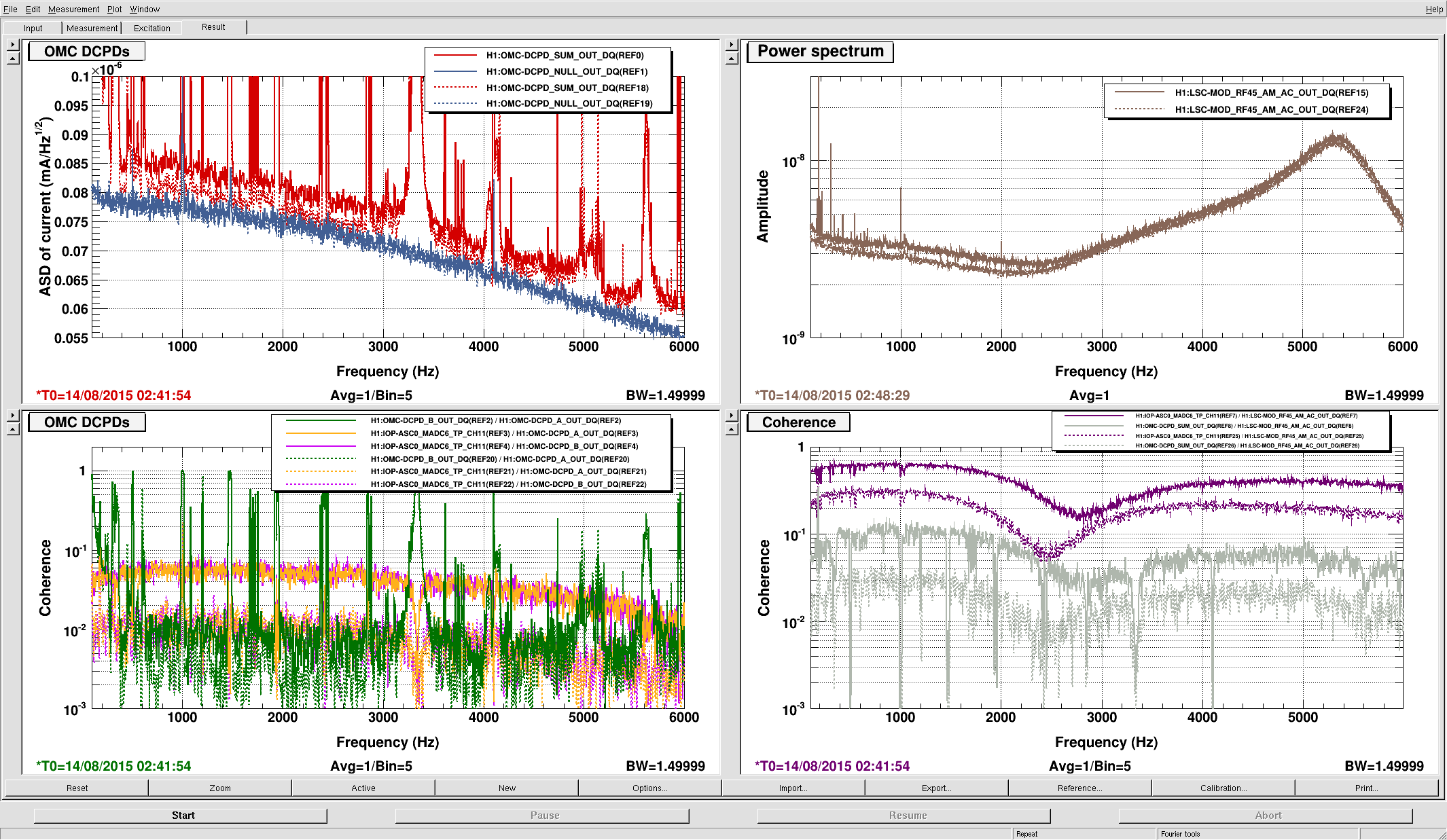
In both QPDA and B, seg1 and seg4 are larger than 2 and 3.
For QPDA, SEG1 is coherent with SEG4 (in-phase) but not with SEG2 and SEG3, while SEG2 is coherent with SEG3 (out of phase) for f>8Hz. SEG1 and SEG2 look kind of out of phase but the lack of coherence means that this doesn't mean much.
For QPDB SEG1 is coherent with SEG2 and SEG4 (1 and 2 in-phase, 1 and 4 out) but not as coherent with SEG3. SEG1 and SEG3 might be in-phase with the same caveat as QPDA SEG1 and SEG2.
(All of these may or may not depend on the alignment and IFO state.)
This doesn't make much sense. If it's TMSX hitting something and exciting mechanical resonances I'd expect some coherence between all segments at around bumps, even if there's some clipping.
If this is a simple electronics problem, different segments should not be coherent with each other.
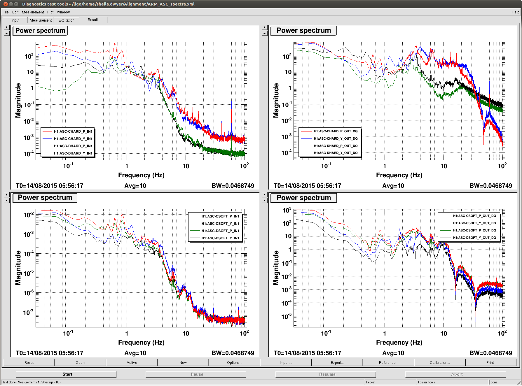
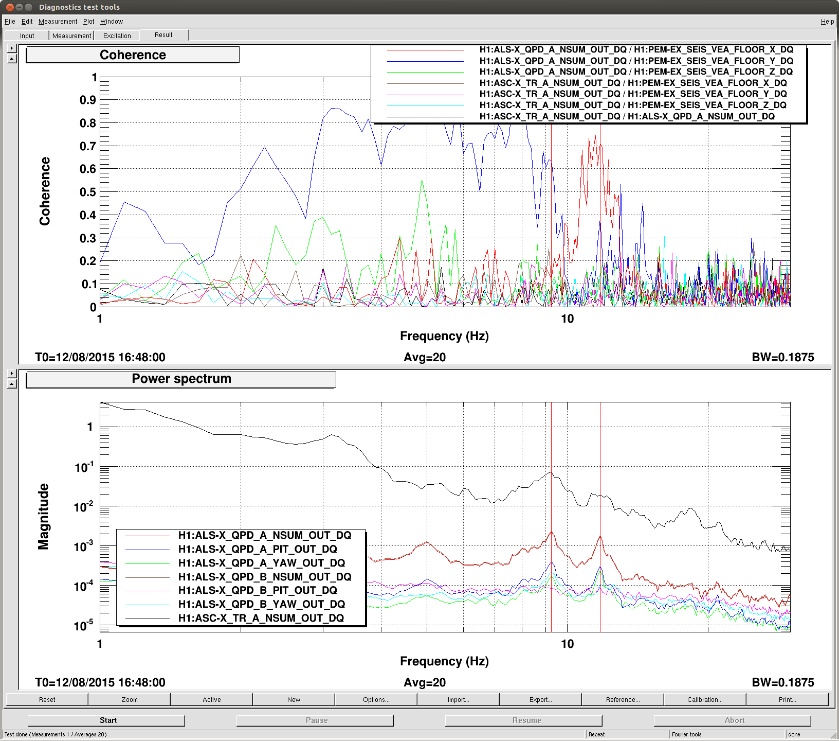
Third attachment: When IR and green are resonant at the same time, for example the twin bumps at 9 and 12Hz or so for IR and green line up. But they are not coherent with each other (black trace at the bottom is the green QPD, black at the top is green/IR coherence).
Green QPDs are coherent with seismometers, IR QPDs are not.
RIN of 9Hz bump for IR and green are on the order of 10ppm/sqrtHz and 1000ppm/sqrtHz, respectively.
TMS BOSEMs are too noisy to detect anything at this frequency (no difference between TMSX and TMSY in this regard).
Question: What are we seeing here?


