corey.gray@LIGO.ORG - posted 23:02, Wednesday 12 August 2015 (20495)
ITMy Roll Mode Addressed
(Dan, Corey)
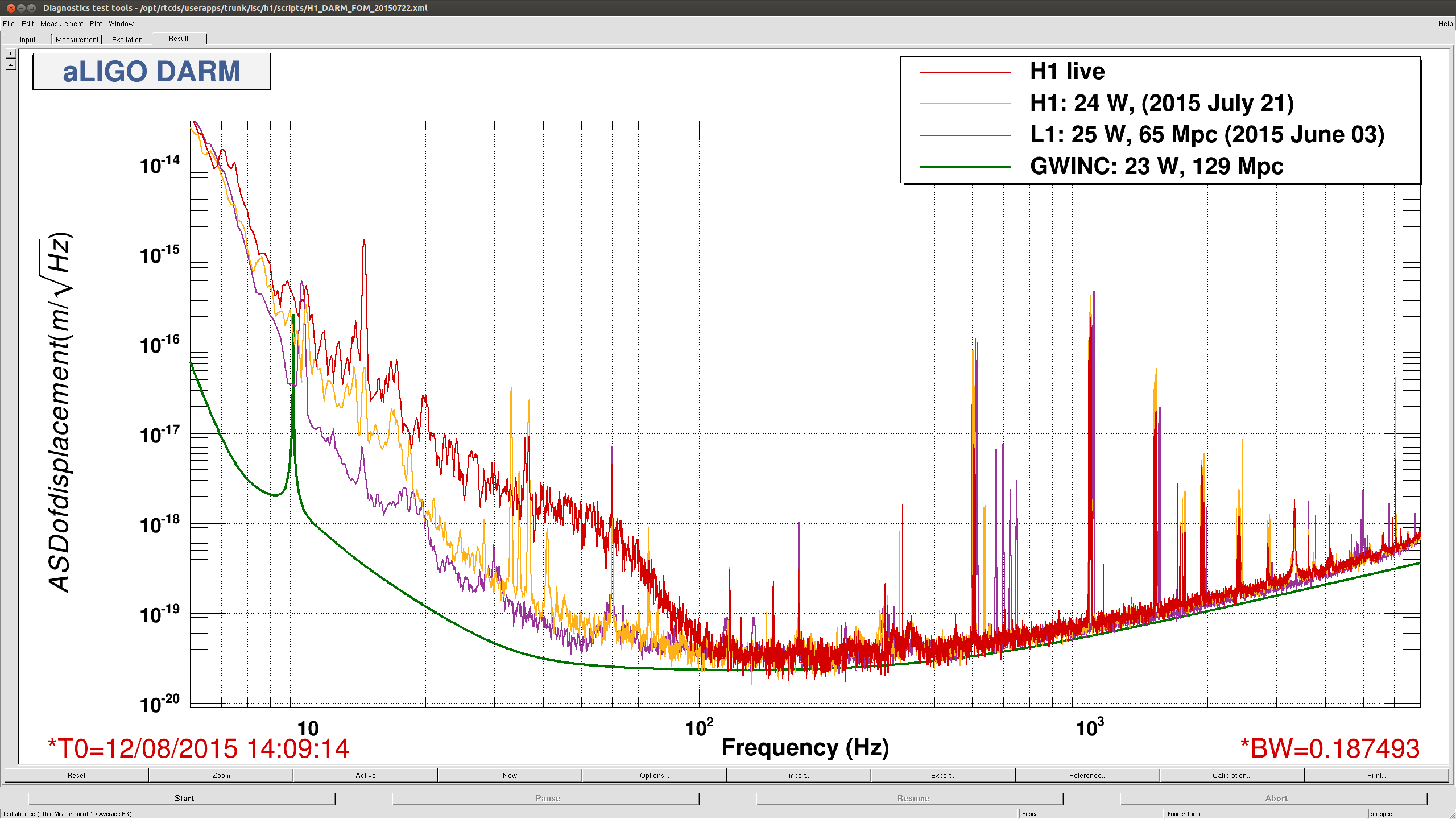
Around 5:30UTC (22:50PT), Dan noticed a rung up roll mode on DARM spectrum, and from the Bounce/Roll monitor, the culprit was ITMy.
Brought up the bounceroll.stp StripTool from the Ops Template & could see ITMroll channel high. From the ITMy SUS screen, opened the DARM BR DAMP filter bank screen.
Initial Values: -60degrees & a gain of +40.
New Values: +60degrees & a gain of -80.
This took care of ITMy, and should be fine for this current lock. Whether we want to keep ITMy like this remains to be seen. Should see how we look after a few locks.