Summary: Scattering studies before the end of O4 suggested that the non-linear vibration coupling that dominates DARM at 20 Hz and contributes significantly up to about 50 Hz, was produced by modulated retro-reflections of the annular beams coming from the bevels of the ITMs and the annular beams from the BS barrel and cage (87758). End-of-run studies, reported here, support these conclusions, and a model estimating scattering noise from vibration time series suggests that reflection from the SR tube MC baffle near HAM4 is also a likely ambient noise source in the unusually high 80-200 Hz region of DARM. The annular beam noise from chamber walls would be mitigated by the already planned ITM cage baffles and the BBS. It is also likely that the HAM4 and SR MC baffle noise would be mitigated by the BBS. The safest route would be to go ahead and install the HAM4 table baffles and treat the HAM4 MC baffle, but we could also wait and see if their noise is mitigated by the BBS.
Noise at 20-50 Hz injection frequencies, likely from 20 and 45 degree annular beams
As noted at the end of alog 87758, the noise in DARM was most consistent with the motions of permanent accelerometers on ITMX, ITMY and the BS, consistent with what would be expected if the annular beams (83050) from optics in these chambers cause scattering noise. We have, since then, mounted temporary accelerometers around these chambers and elsewhere to further test this hypothesis, particularly placing accelerometers on the vacuum envelope at locations just outside of where the annular beams hit the inside of the enclosure.
We used two of the three vacuum enclosure techniques mentioned in 87758, the beating shaker technique and a variant of the consistency test for sweeps from shakers at different locations. However, we were not able to use the third technique, the hand-held shaker test in the region close to the vertex because of magnetic coupling, likely to magnets on the BS, even though the coil is much smaller than those in our other magnetic shakers.
Consistency technique
The accelerometers that were most consistent for 3 sets of 3-shaker injections were temporary accelerometers mounted near where the ITM annular beams hit the bellows of the spool pieces between the ITMs and BSC2, one for each ITM, and the permanent accelerometers “BSC3_Y” and “MCtube”. The BSC3-Y accelerometer is near where the annular beam from the BS likely shines (See Figure 1), but the MC tube accelerometer is probably coincidental because when a shaker was moved to the MC tube, the accelerometer there was no longer consistent with DARM.
Beating shaker technique
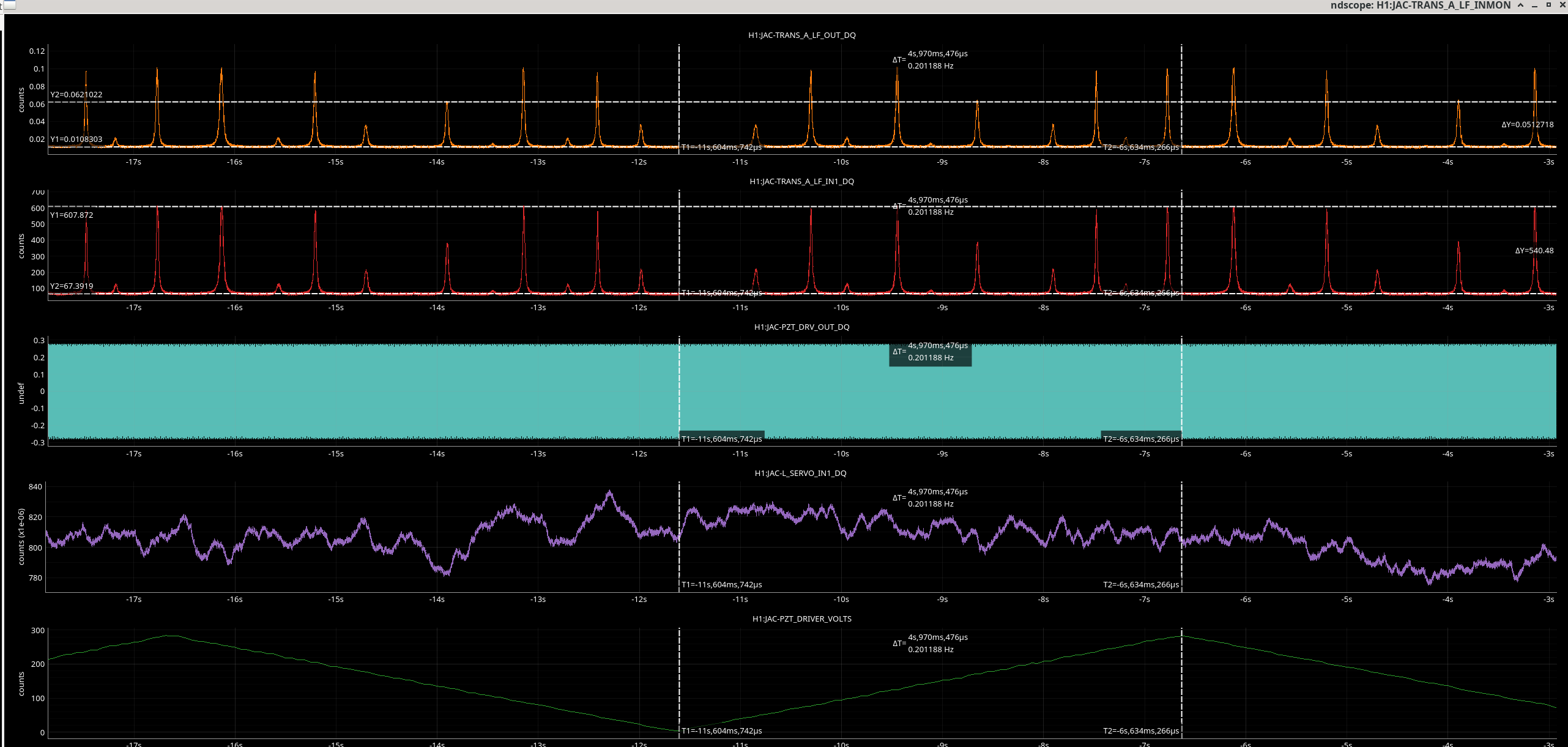
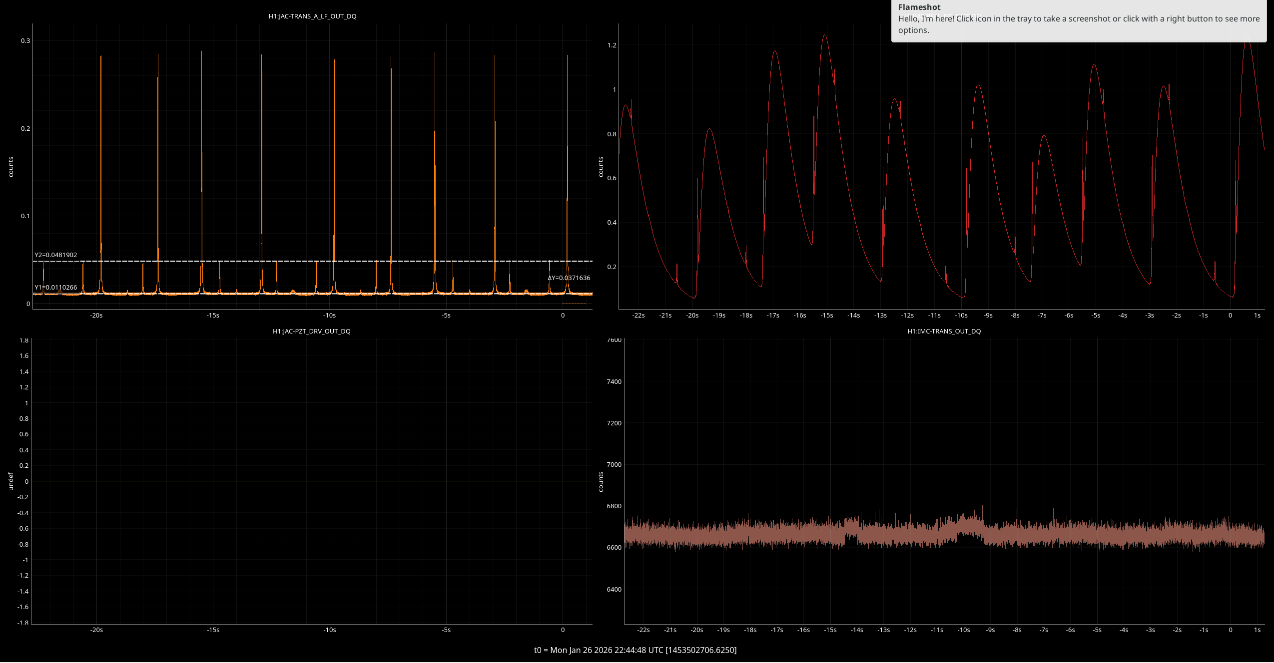
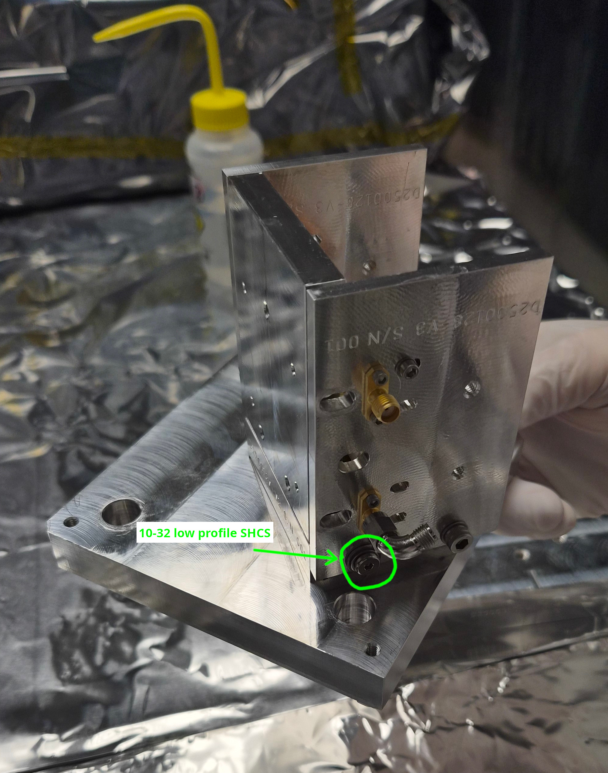
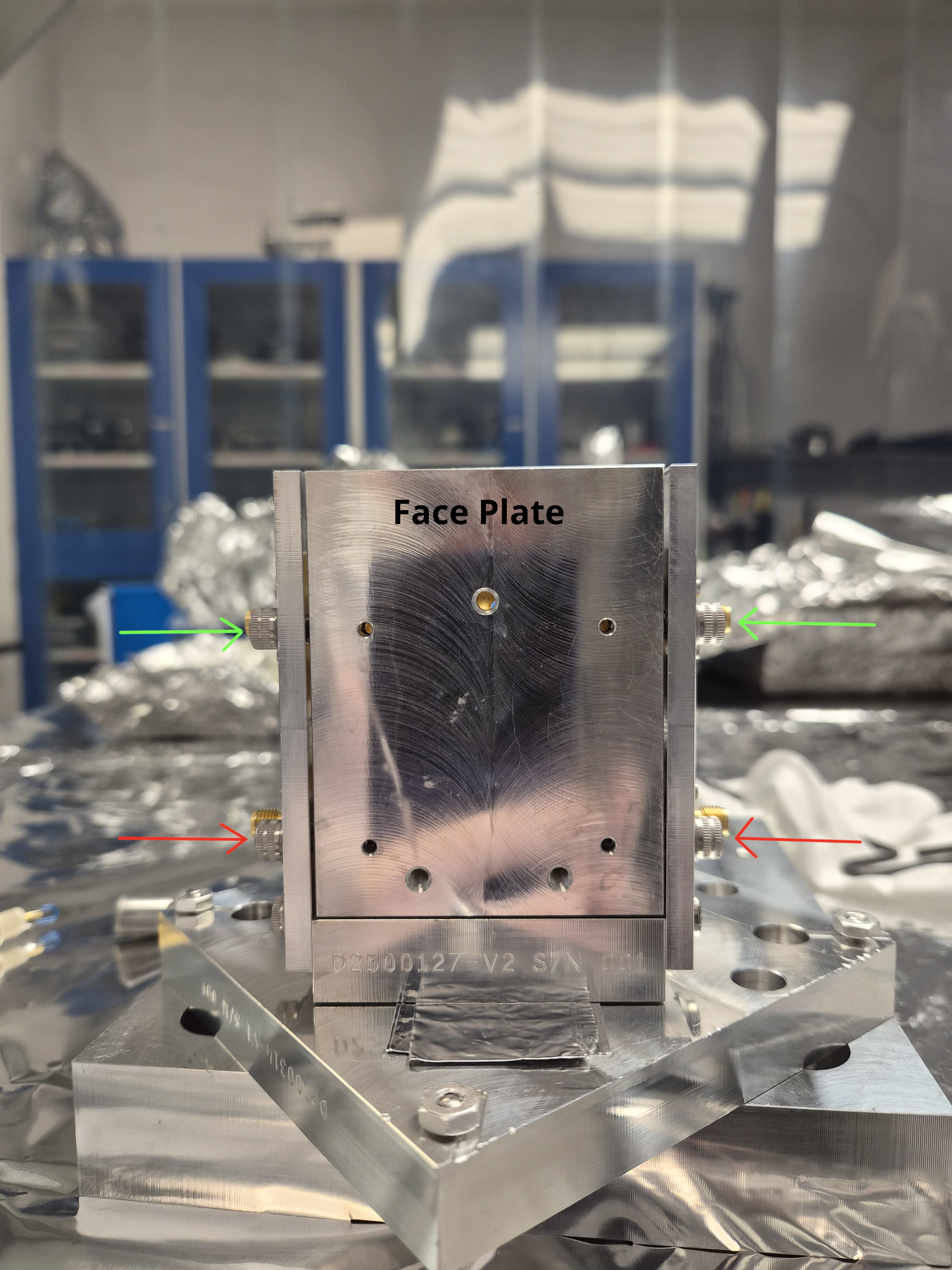
The accelerometers mounted just outside where the ITM annular beams hit were also the most consistent with DARM for the beating shaker technique. Figure 1 shows results of one of the most convincing beating shaker tests. A piezo shaker was mounted near where the ITMX annular bevel beam hits the bellows of the BSC2-BSC3 spool-piece (see photograph here ). A second shaker was mounted on the old H2 BSC7. The shakers were set to 31.005 Hz and 31 Hz respectively. The amplitudes of the two shakers were adjusted so that each individually produced the same amplitude of peak in DARM, before they were both turned on. Figure 2 shows that the timing of the beat envelope of the accelerometer on the bellows where the annular beam hits, matches the beat envelope timing in DARM, while timing for 14 other accelerometers that I examined (7 are shown) did not match as well. Also, the modulation depths of the beat in the accelerometer signals are greatest in this region of the enclosure, indicating that the two shaker peaks have similar amplitudes in the accelerometers near this location, like the two peaks in DARM (by adjustment).
Potential noise at 80-200 Hz from MC baffle in SRtube near HAM4
Early in O4 we found that the MC baffles in the input arm were causing noise in DARM (74175). We fixed this by angling the baffles further (76969). We also found that the MC baffles in the output arm could make scattering noise but that this was at a lower level than the baffles in the input arm (74175).
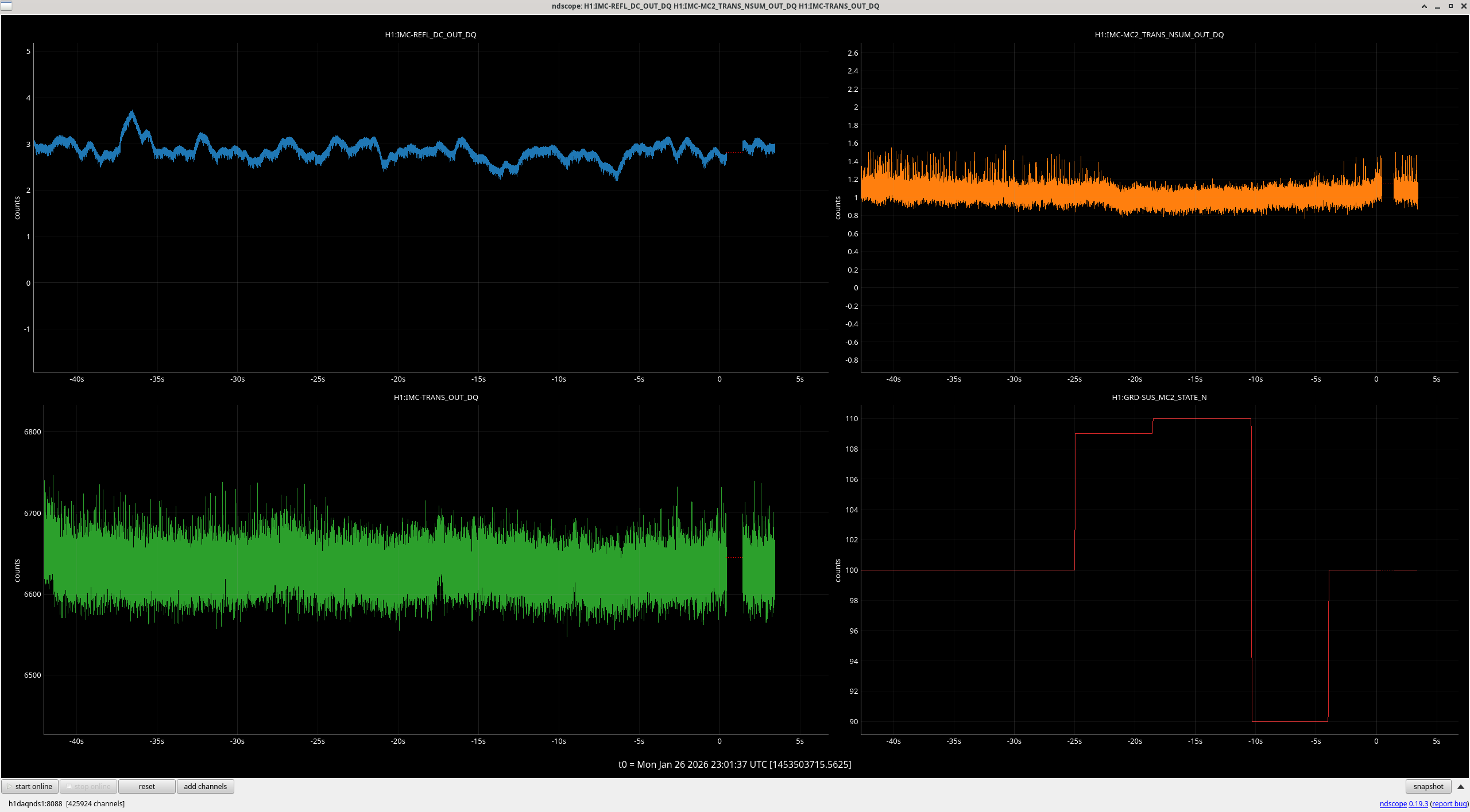
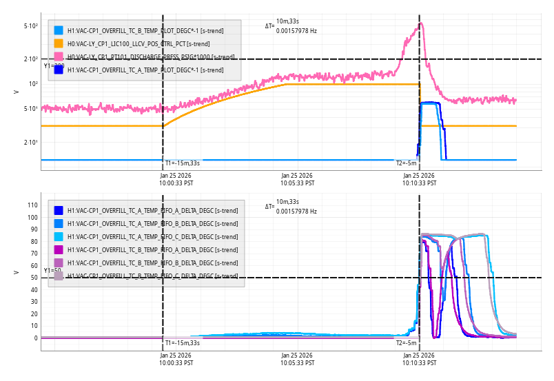
During recent end-of-run studies, I shook the output arm to asses the current status of scattering noise from these output arm baffles. The injections made noise in DARM but It was difficult to determine whether injection-free ambient vibration levels would affect DARM, because the noise increased with frequency rather than forming a flat shelf, I think due to the optical transfer function of scattering noise from the SR cavity back into the interferometer (LIGO-T060073). So I included a "BSSR" optical transfer function in my new model which combines accelerometer and seismometer time series to estimate the phase noise and radiation pressure noise from a source at any point in time (scattering noise, like the underlying vibration, often varies greatly in time). I was able to match the time evolution of the scattering noise in DARM during the vibration sweep by filtering external accelerometer data using resonant gains to simulate the resonances of the internal baffles. I used two resonances at 13.2 and 14.2, with Qs in the hundreds to simulate the DARM response - the results are shown in Figure 3.
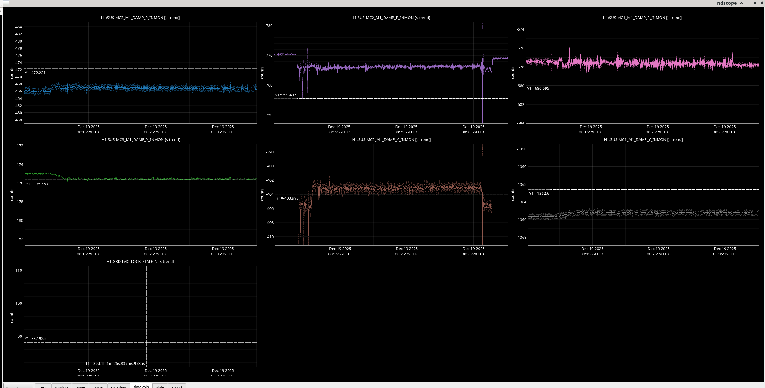
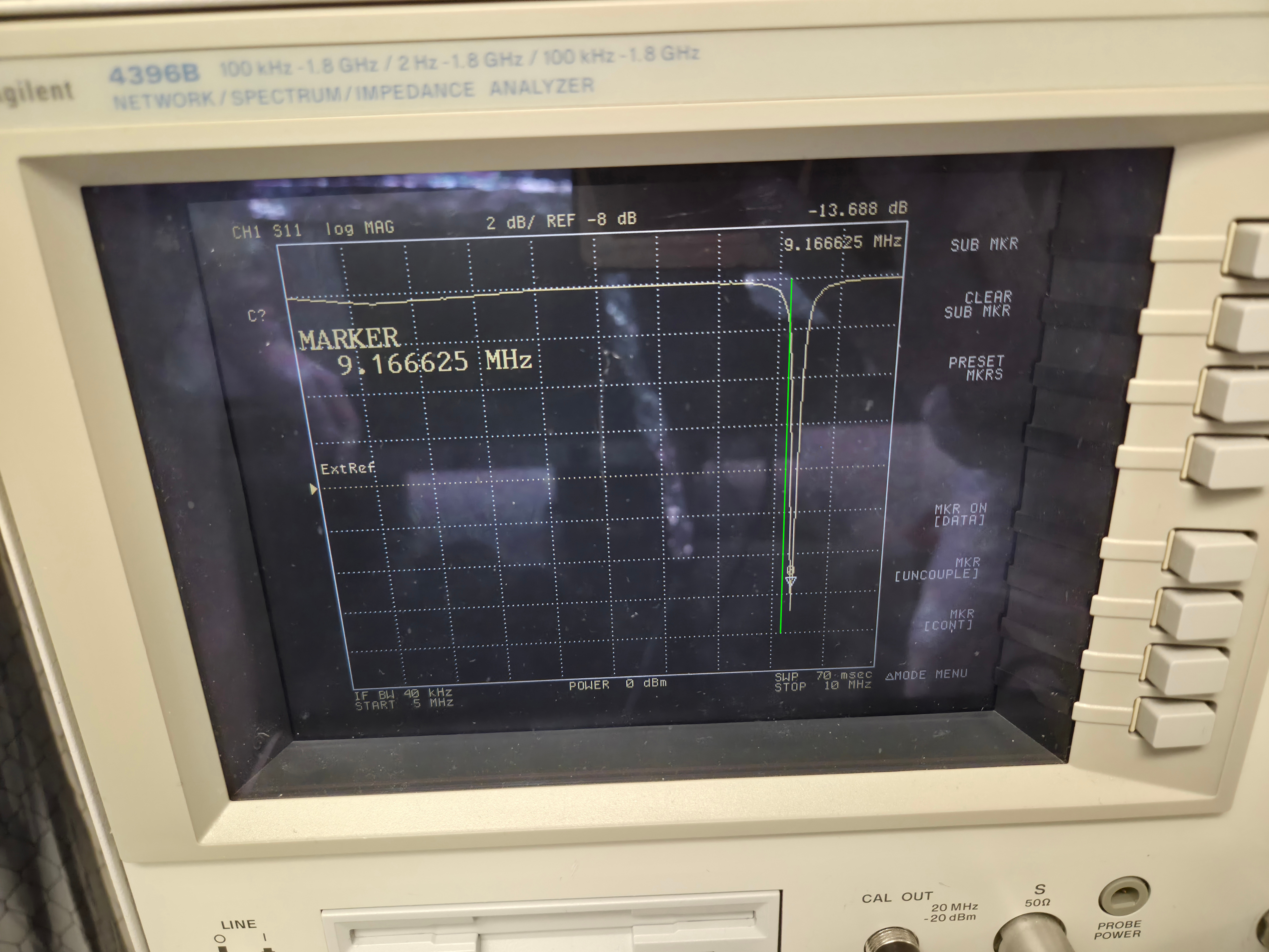
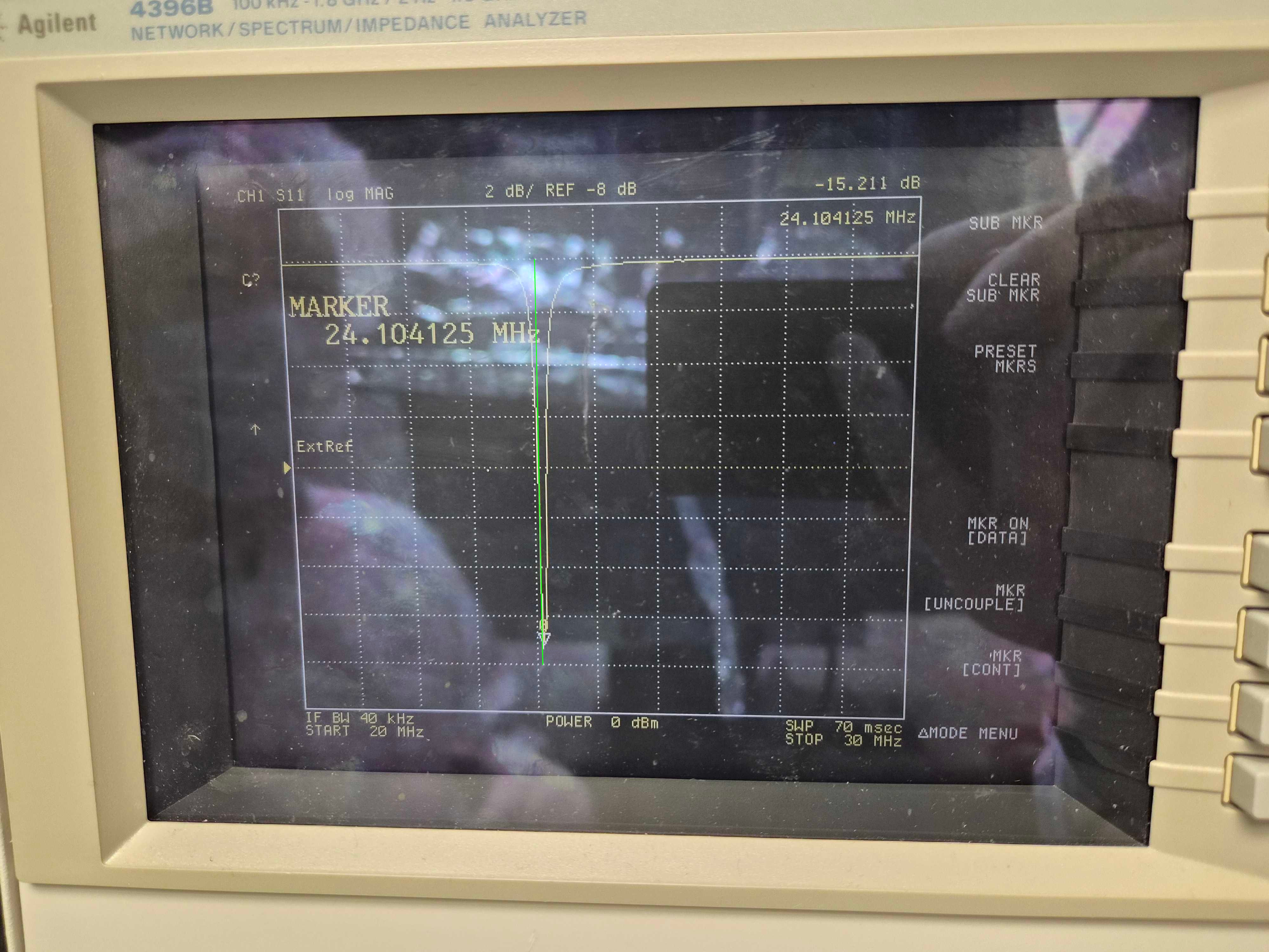
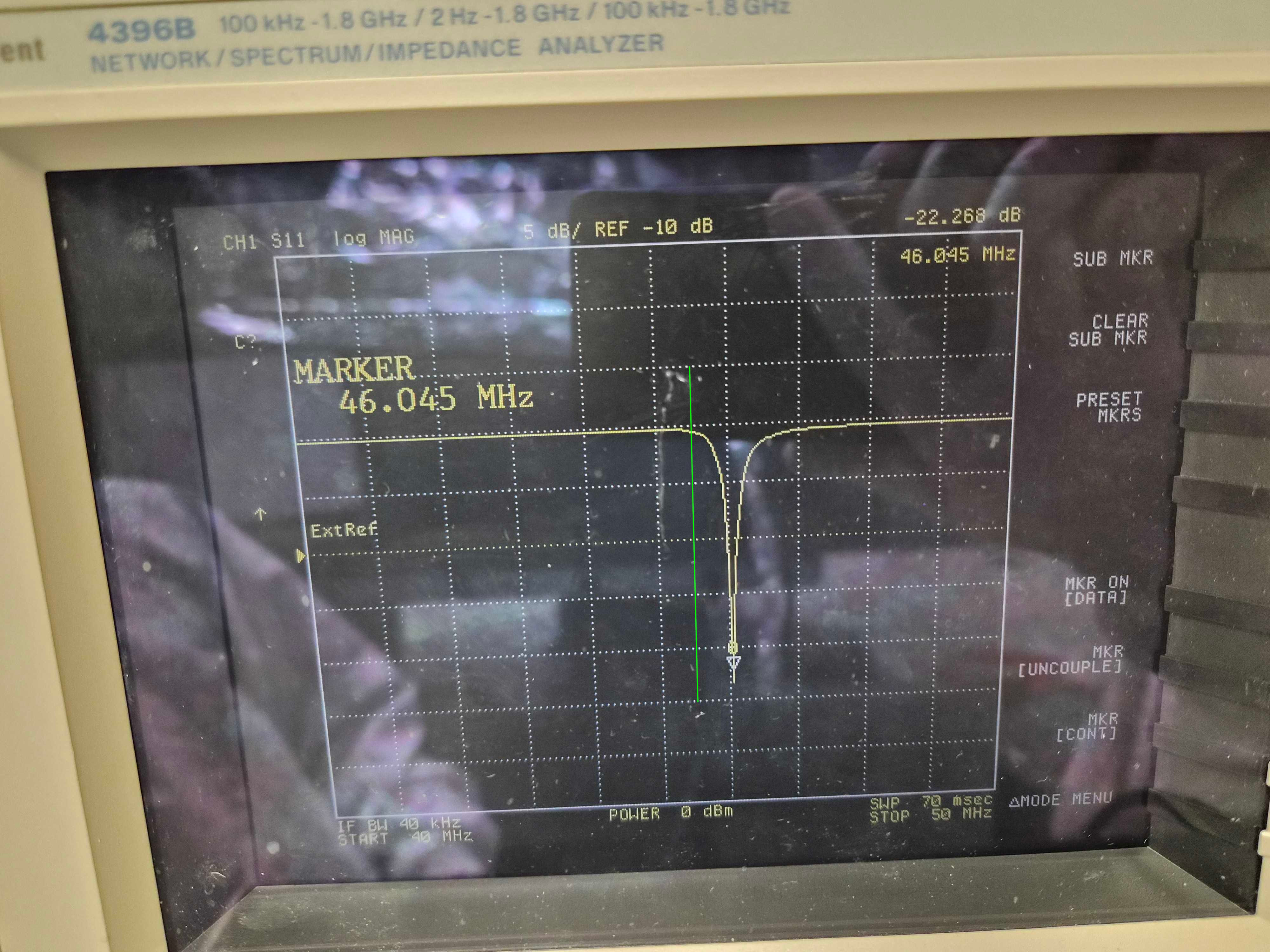
However, the Qs that were needed seemed too high because Corey and I had tried to damp these (39156), and the only evidence that the source was the baffles was the low resonant frequency, consistent with the measured frequency of input arm MC baffles. But the low frequency resonance might also be a resonance of the vacuum enclosure itself, so I decided to get the Qs and resonant frequencies from the baffles directly, using a laser vibrometer. I found that The MC (eye) baffle by HAM5 has a resonance of 12.1 Hz, the MC Baffle by HAM4, at 13.3 Hz, and the SR tube has a resonance at 14 Hz. Thus, based on the 13.2 and 14.2 Hz frequencies that made the original model reproduce DARM noise, the likely source of the scattering noise is the eye baffle by HAM4. Using the measured Qs, resonances, and a simplified mechanical transfer function from the permanent accelerometer that was present when I did the original sweep to an accelerometer that I mounted last week right outside the baffle, I got the results shown in Figure 4 (the permanent accelerometer I used for Figure 3 underestimated tube motion at the location of the baffle which was why I had to use such high Qs - the measured Qs were 5 and 10, more consistent with our damping). The predicted level of noise in DARM for ambient vibration levels in Figure 4 is slightly lower than the more naive model of Figure 3, getting as close as a factor of 3 below the current noise floor in the 80-200 Hz region.
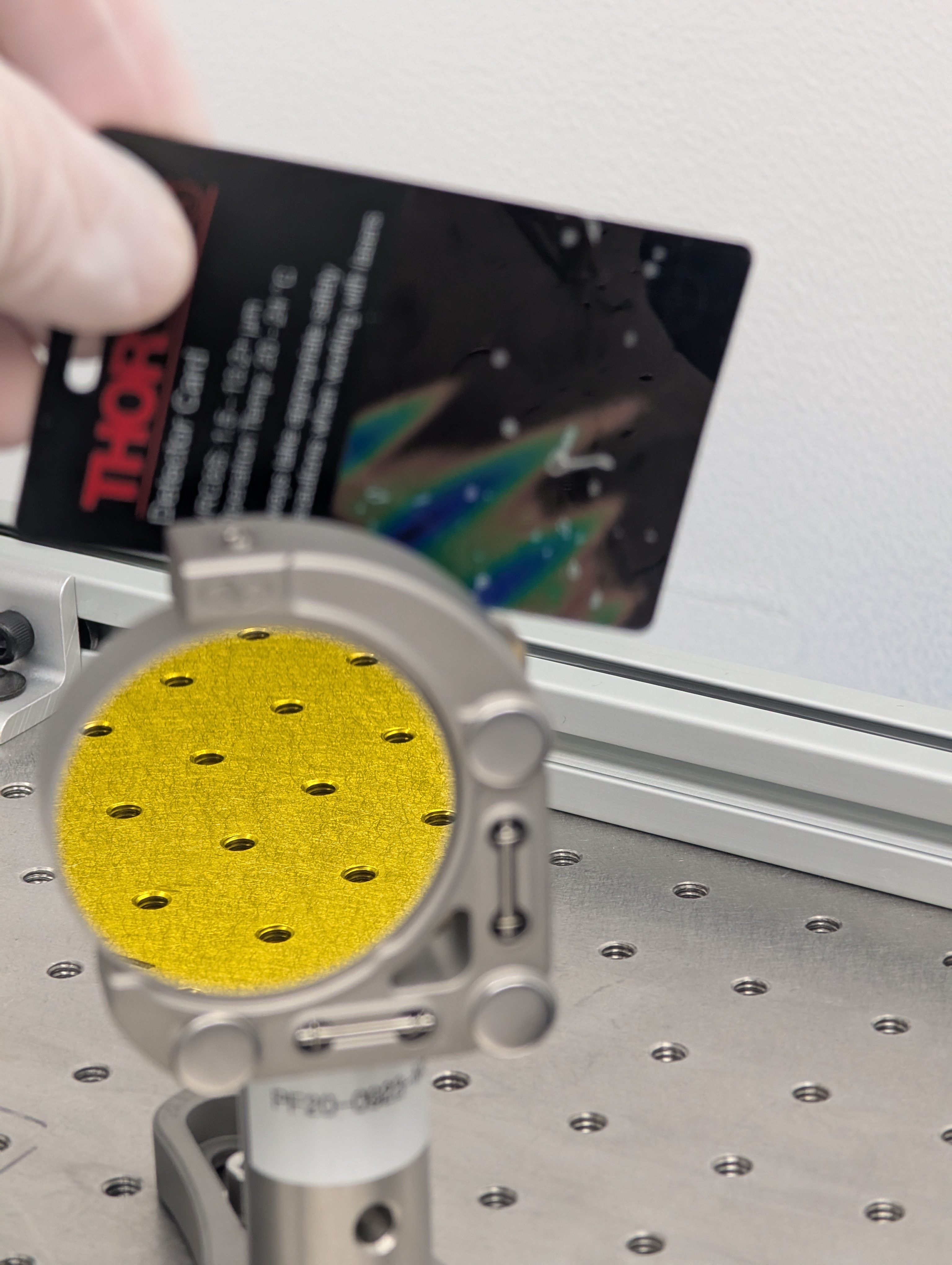
One possibility is that the eye baffle is reflecting light in the 45 degree annular beam coming from the BS. Based on the evidence for this in Figure 5, and the increasing evidence that the annular beams are bright enough to be problematic, I would guess that there is about an 80% likelihood that this is the source of the SR tube noise and that the Bigger Beam Splitter would mitigate this noise source. This was also my assessment for the noise produced by shaking the HAM4 table (87758), and I suggested that we could wait until after the installation of the BBS, and then mount table baffles if the noise had not been mitigated. I think this would also be a reasonable path for the eye baffle, waiting to see if the noise goes away with the BBS, and improving the baffle if it does not. Of course the safest path would be to mitigate the MC baffle(s) and install the HAM4 table baffles anyway. If we do mitigate the MC baffle(s), I would want to remove or treat the central portion of the baffle(s), as well as, or instead of, increasing the angle of the baffle(s) like we did in the input arm. This is because the reflection site, as evident in Figure 5, is likely to be in the central region of the baffle.
-Robert, helped especially by Sam and Joan-Rene