Jenne, Sheila
On the theory that our slow instability at 24 Watts (alog 19855 )is caused by DHARD signal which contaminates the SOFT signals and the AS_C signal therefore gets into the SRC WFS, we decided to boost the DHARD loops. For pitch this was easy, I just moved the pair of complex poles in the existing boost down from 0.2 Hz to 0.02 Hz. This worked the first time.
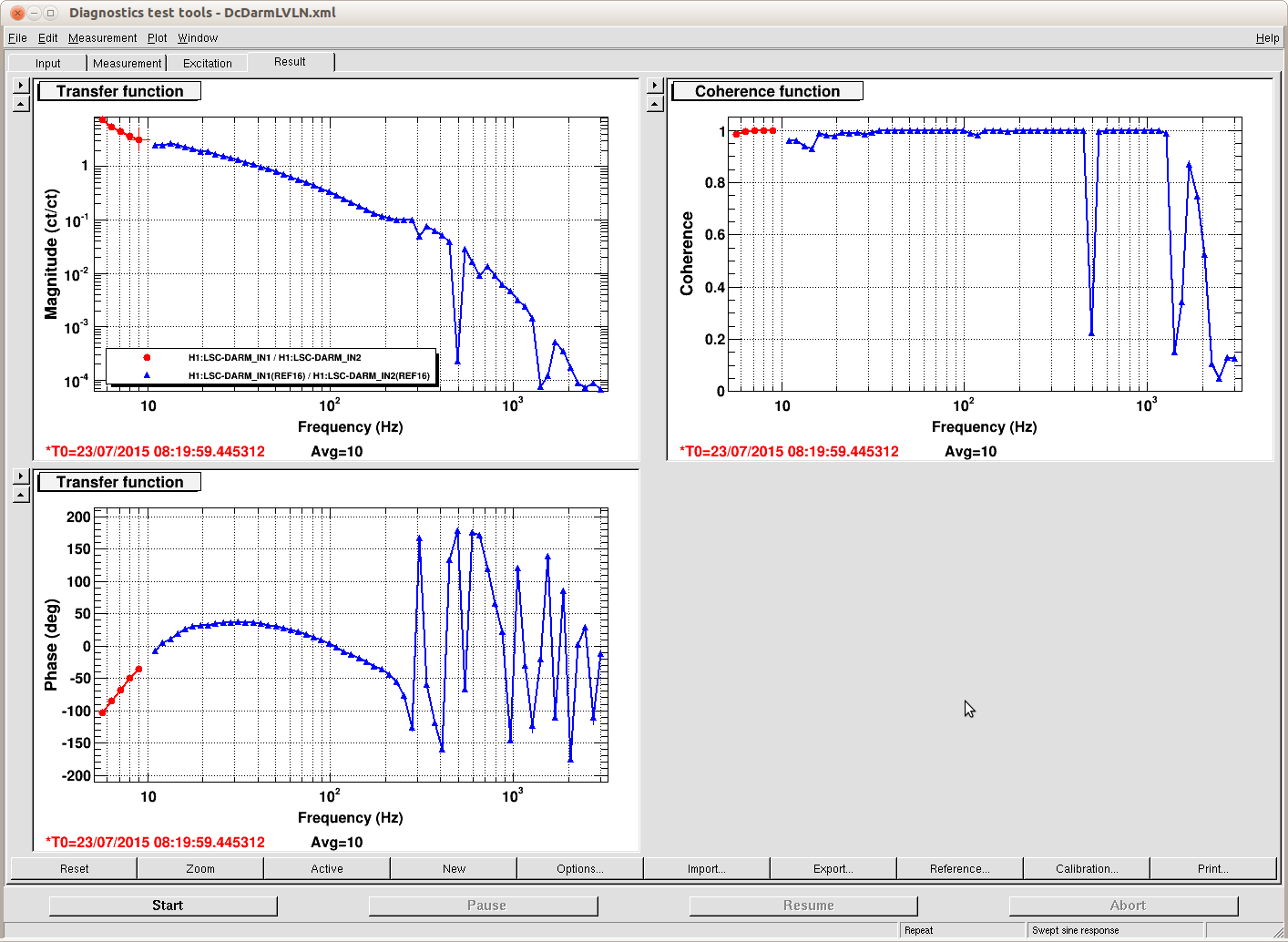
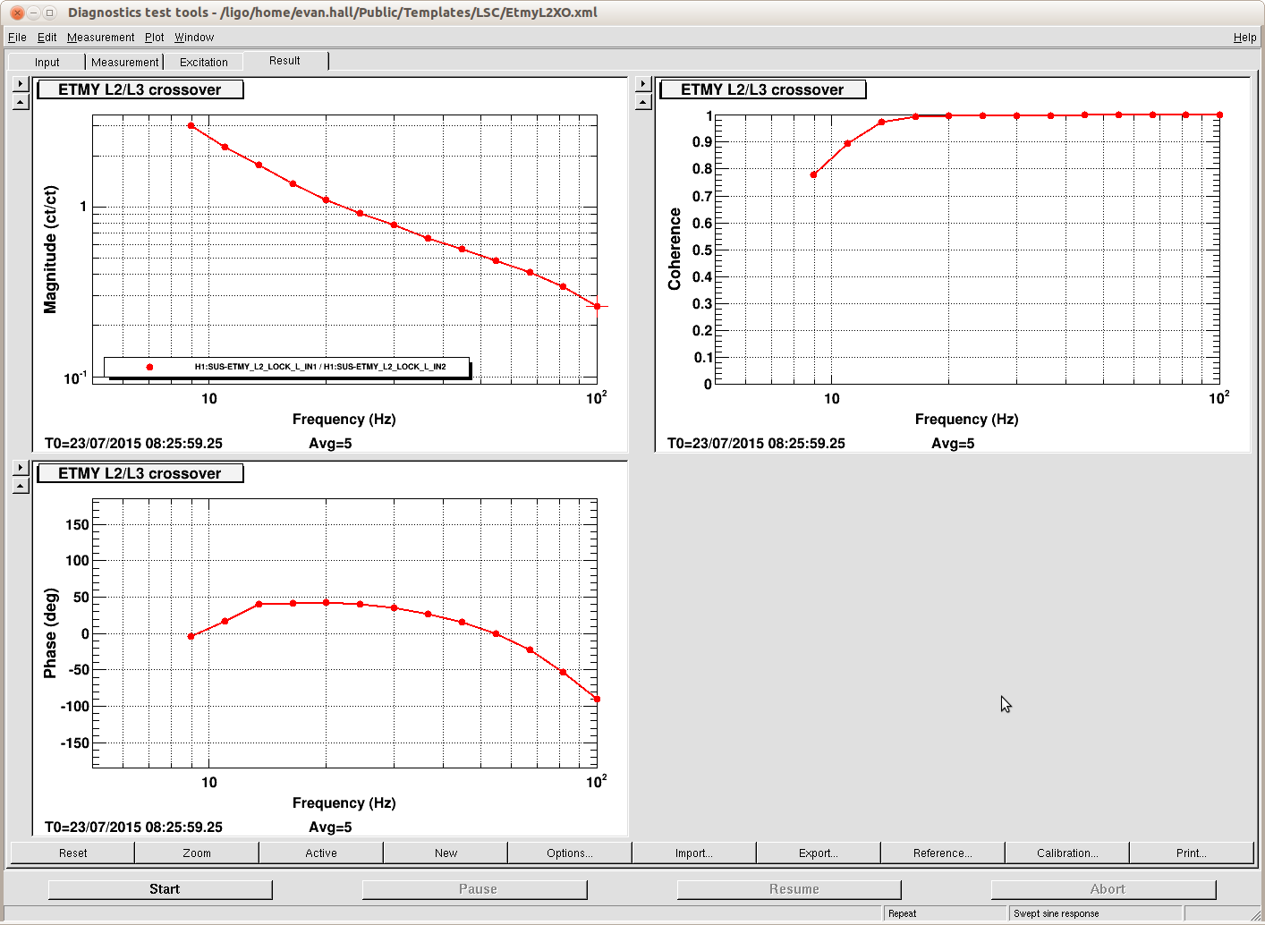
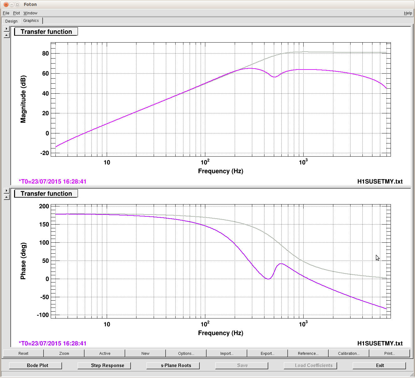
For yaw I tried similarly to lower the poles in the existing boost to 0 Hz, but this caused an instability that broke the lock on power up. Jenne and I then had a look at the transfer function and remembered how not great this loop was. In fact at 3 Watts it had about 7 ugfs, the lowest one just under 0.3 Hz. We made a small adjustment to the plant inversion to get rid of two of the (the new plant inversion is invY2, the Q of the 1.8 Hz pole is higher), we increased the gain in the input matrix from 1 to 3, and last I modified the boost which had been a pair of 0.4Hz poles, Q of 1.2, and is now a pair of 1 Hz poles, Q of 2. The first attached screenshot shows the transfer function before and after these changes, measured at 3 Watts. This loop currently doesn't have any roll off, but we don't have much phase margin to spare. The second attached screenshot shows measurements at 3 different powers, reference numbers are in the legend of the phase plot. As we increase the power, the gain below the resonance drops as expected, this means that at 24 Watts we just barely have any gain even after increasing this gain by about 20dB.
Aside: Part of the reason that we had trouble designing this loop in the first place is that during the CARM offset reduction the gain changes by about 30dB, and the resonance move. I thought that one way of making things easier would be to use the dynamic power normalization, which we haven't used here yet. Scaling by POP DC would be about right, we could lower the gain by 26 dB between the point where we turn on the loop and on resonance, so we could design a loop with only one ugf above all the structure, and not need so much gain margin. I tried this, but it didn't work. I tried turning up the gain in the input matrix, and turning it back down. That was fine, so I tried to use the power scaling to do exactly the same thing, and that broke the lock. I don't know if I've been fooled by some hidden normalization, but I don't see anything in the model.
Jenne, Sheila
On the theory that our slow instability at 24 Watts (alog 19855 )is caused by DHARD signal which contaminates the SOFT signals and the AS_C signal therefore gets into the SRC WFS, we decided to boost the DHARD loops. For pitch this was easy, I just moved the pair of complex poles in the existing boost down from 0.2 Hz to 0.02 Hz. This worked the first time.
For yaw I tried similarly to lower the poles in the existing boost to 0 Hz, but this caused an instability that broke the lock on power up. Jenne and I then had a look at the transfer function and remembered how not great this loop was. In fact at 3 Watts it had about 7 ugfs, the lowest one just under 0.3 Hz. We made a small adjustment to the plant inversion to get rid of two of the (the new plant inversion is invY2, the Q of the 1.8 Hz pole is higher), we increased the gain in the input matrix from 1 to 3, and last I modified the boost which had been a pair of 0.4Hz poles, Q of 1.2, and is now a pair of 1 Hz poles, Q of 2. The first attached screenshot shows the transfer function before and after these changes, measured at 3 Watts. This loop currently doesn't have any roll off, but we don't have much phase margin to spare. The second attached screenshot shows measurements at 3 different powers, reference numbers are in the legend of the phase plot. As we increase the power, the gain below the resonance drops as expected, this means that at 24 Watts we just barely have any gain even after increasing this gain by about 20dB.
Aside: Part of the reason that we had trouble designing this loop in the first place is that during the CARM offset reduction the gain changes by about 30dB, and the resonance move. I thought that one way of making things easier would be to use the dynamic power normalization, which we haven't used here yet. Scaling by POP DC would be about right, we could lower the gain by 26 dB between the point where we turn on the loop and on resonance, so we could design a loop with only one ugf above all the structure, and not need so much gain margin. I tried this, but it didn't work. I tried turning up the gain in the input matrix, and turning it back down. That was fine, so I tried to use the power scaling to do exactly the same thing, and that broke the lock. I don't know if I've been fooled by some hidden normalization, but I don't see anything in the model.