J. Kissel, B. Weaver, D. Barker, J. Batch
After the completion of the upgrade of the BIOS of the fast front ends for the ETM SUS, we had tried compiling the front-end models against RCG branch 2.9, such that we could inherit both fixes to the True RMS part. It hasn't been documented anywhere other than the initial ID of the bug (see LHO aLOG 19658), but RCG 2.9.5 (released by Rolf Bork on Friday afternoon) fixes the "initialization problem" with the true RMS part, and a further fix to the part's "accumulation issues" had been checked into the branch 2.9 last night by Matt Evans. The hope was that we could get both fixes by compiling against the branch.
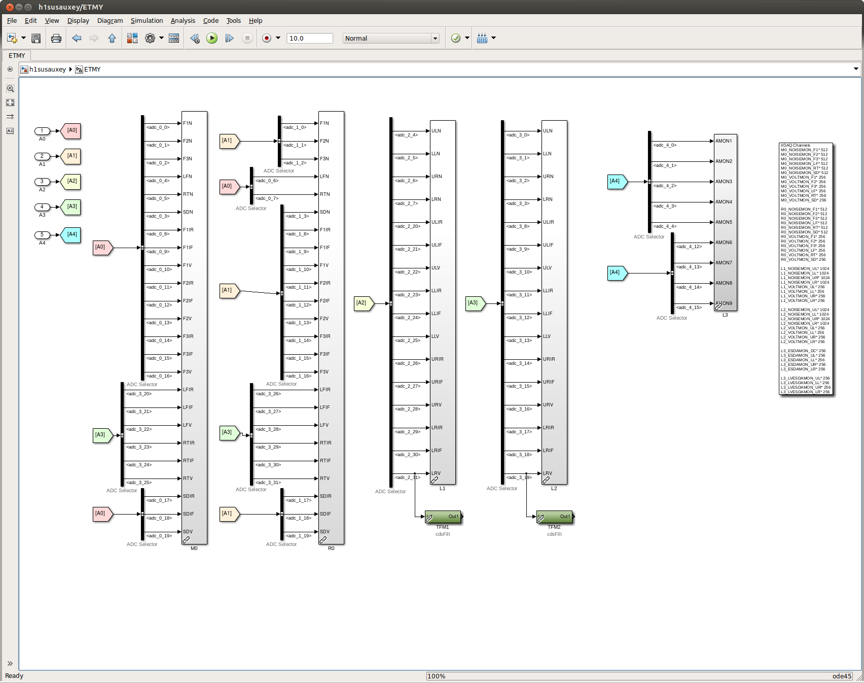
Beginning with the H1 SUS ETMY model (which had previously been compiled against RCG tag 2.9.4), it successfully restarted with the existing code. However, when we compiled against the branch, during the restart the BURT restore of the safe.snap SDF file failed. We were able to reproduce this twice: for many channels (275 the first time, and 277 the second time, according to the SDF system; often with filter bank settings, but not matrix settings), the correct safe.snap was loaded, and then ~3 seconds later come other bad value was restored in its place. We were finally able to successfully restart and automatically restore with the code compiled against the RCG tag 2.9.5.
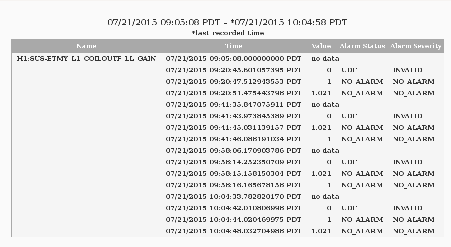
The attached conlog screenshot documents this problem with a single one of these bad channels. The restart at 9:20 PDT is the restart with existing code (had been compiled at 2.9.4). The restarts at 9:41 and 9:58 are with the code compiled with branch 2.9. The (successful) restart at 10:04 is compiled against the tag 2.9.5.
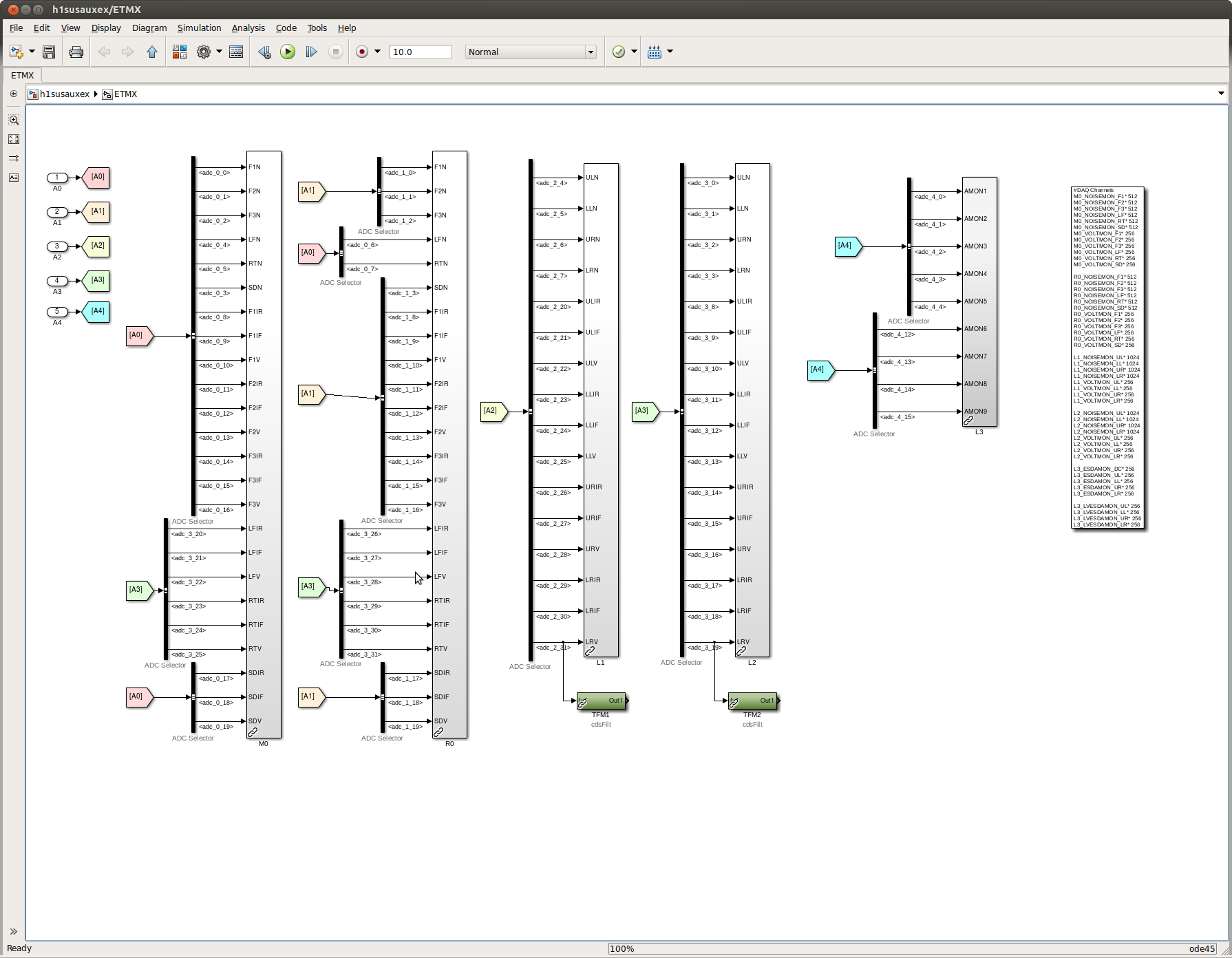
Further, ~30 minutes later, we noticed that ETMY's IOP DAC channels were zero, while the user model was requesting output. To resolve this, we had to kill all user models on the front end, and restart the IOP model. This theoretically should have been done already, given that, after the BIOS upgrade, the all front end models start from scratch. But, we shrug, and say "must not have stuck!" Indeed this same problem (code compiled against RCG 2.9.5, successfully restored, and subsequent zero IOP DAC outputs) occurred on ETMX as well, so we also did a second full restart of all models in that front end after the BIOS upgrade restart.