This is a summary of the thermal test we did yesterday (alog 20146) in which we changed the power of the CO2 laser for ITMX as a part of noise coupling study.
We were interested in four quantities as listed below together with some observations.
-
Frequency noise coupling can be lowered by a factor of 10
-
Intensity noise coupling does not dramatically improve. A factor of 2-ish at best if we tune the CO2X power.
-
SRCL coupling was not sensitive to the CO2X power. It changed by 30% or so.
-
DARM coupled cavity pole frequency was stable throughout the test. It seems insensitive to the CO2X power.
Here are some plots. All of them are pltos of time series data starting at 2015-08-02 22:35:00 UTC for 8 hours. The interferometer was locked at the first 10 minutes of the plots and kept locked for more than 8 hours. Our thermal test start at around t = 2.7 hours. The time stamps for important activities are written in Evan's alog (alog 20146).
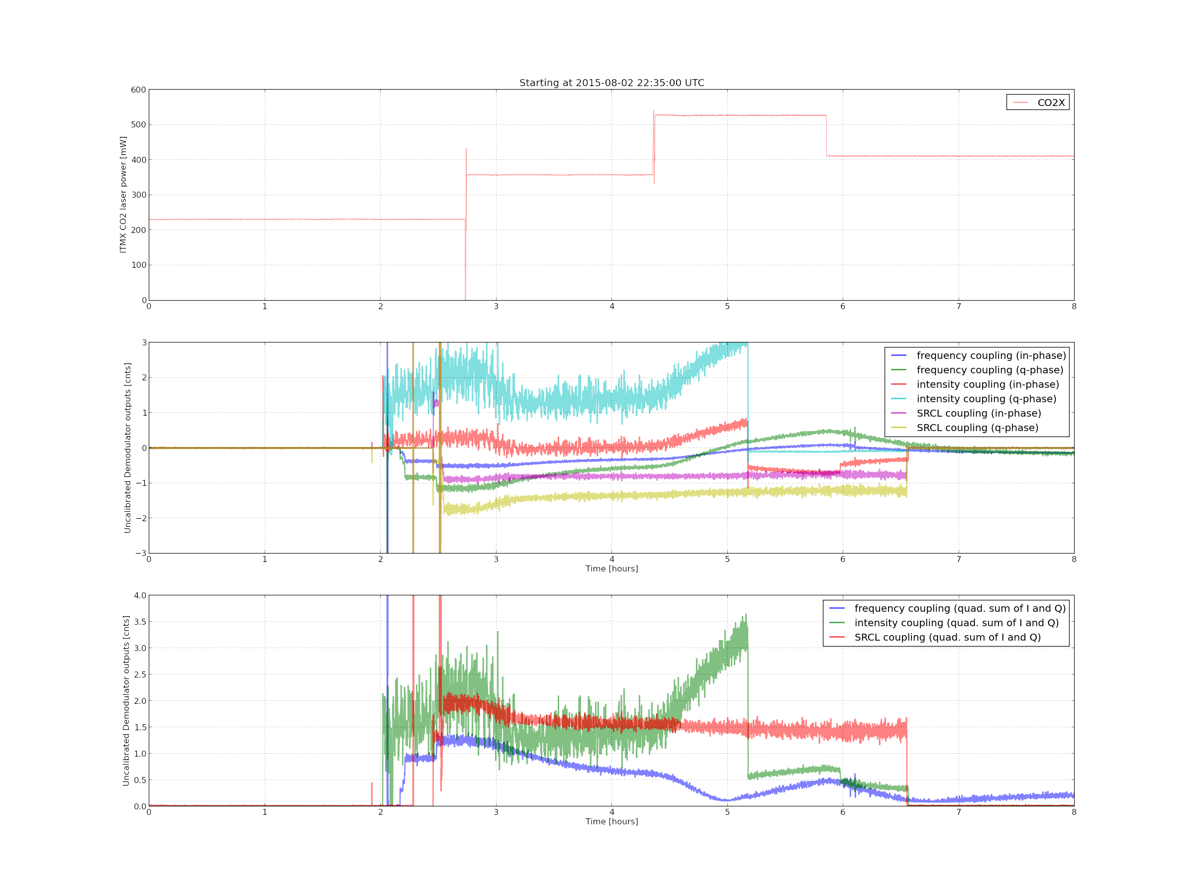
[1 st plot]
This plot is meant for showing how the noise couplings evolved during the test. The middle panel shows the measured coupling coefficients using the LSC front end demodulators. The signals are measured as in- and q-phases which are demodulated with cosine and sine local oscillators respectively. Since the excitation were done by independent awgs, the i- and q- phase don't mean anything except that they are 90 deg apart. Meaningful data start several 10 minutes before the CO2 power was changed. The intensity noise coupling shows an abrupt change at around t = 5.2 hours because Stefan closed the 2nd loop to try out a configuration for the maximum intensity suppression (alog 20155). Similarly, the SRCL excitation was disabled at around t = 6.5 hours resulting in a sharp drop in the measured I and Q signals. The bottom panel shows quadratic sum of the I and Q signals for frequency, intensity and SRCL couplings. The definition of the quadratic sum here is sqrt( I^2 + Q^2) in order to show the absolute magnitude of the couplings.
The in- and q-phase signals of the frequency noise coupling experienced a zero crossing -- but at different times as shown in the middle panel. After the frequency noise was found to be overshot, Evan and Stefan tuned the CO2 power to 410 mW in order to bring the frequency noise back to a point where the coupling is minimized. This tuning attempt seems to be successful because the coupling settled to a small number and roughly a factor of 10 smaller than the one when we started.
Intensity noise coupling appeared to be sensitive to the thermal tuning as well. However it did not show a zero crossing. As far as the tested CO2 power range is concerned, the best reduction in the coupling was only a factor of 2, and the minimum point does not coincide with the one for frequency noise.
SRCL coupling initially appeared to be responsible to the thermal tuning, however it then behaved as if it was not as sensitive as before any more for some reason. In any case, the variation was only 30% or throughout the test.
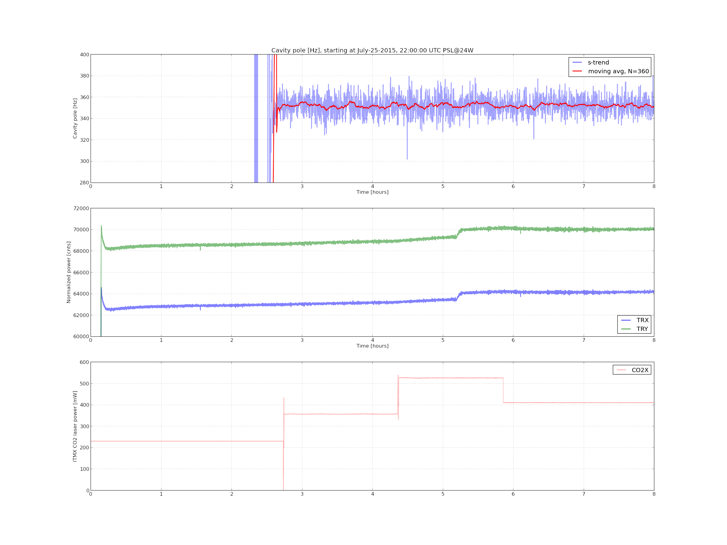
[2nd plot]
This plot shows cavity pole frequency and arms' transmitted light in time series. As shown the cavity did not show a obvious change and in fact, it seems insensitive to the CO2X. A meaningul measurement starts at around t = 2.5 hours since we were setting up a demodulator for it right before the measurement started.
As for the transmitted light, there was a slowly varying component which raised the power level as a function of time. Since the slow variation was present from the beginning, this might be some other component independently of our test. There was a jump in both TRX and TRY which coincided with the time when the 2nd loop ISS was closed. So this must be something induced by a slightly different diffraction power in the AOM of the ISS. So, I don't see any obvious sign of improvement or degradation in the power recycling gain.
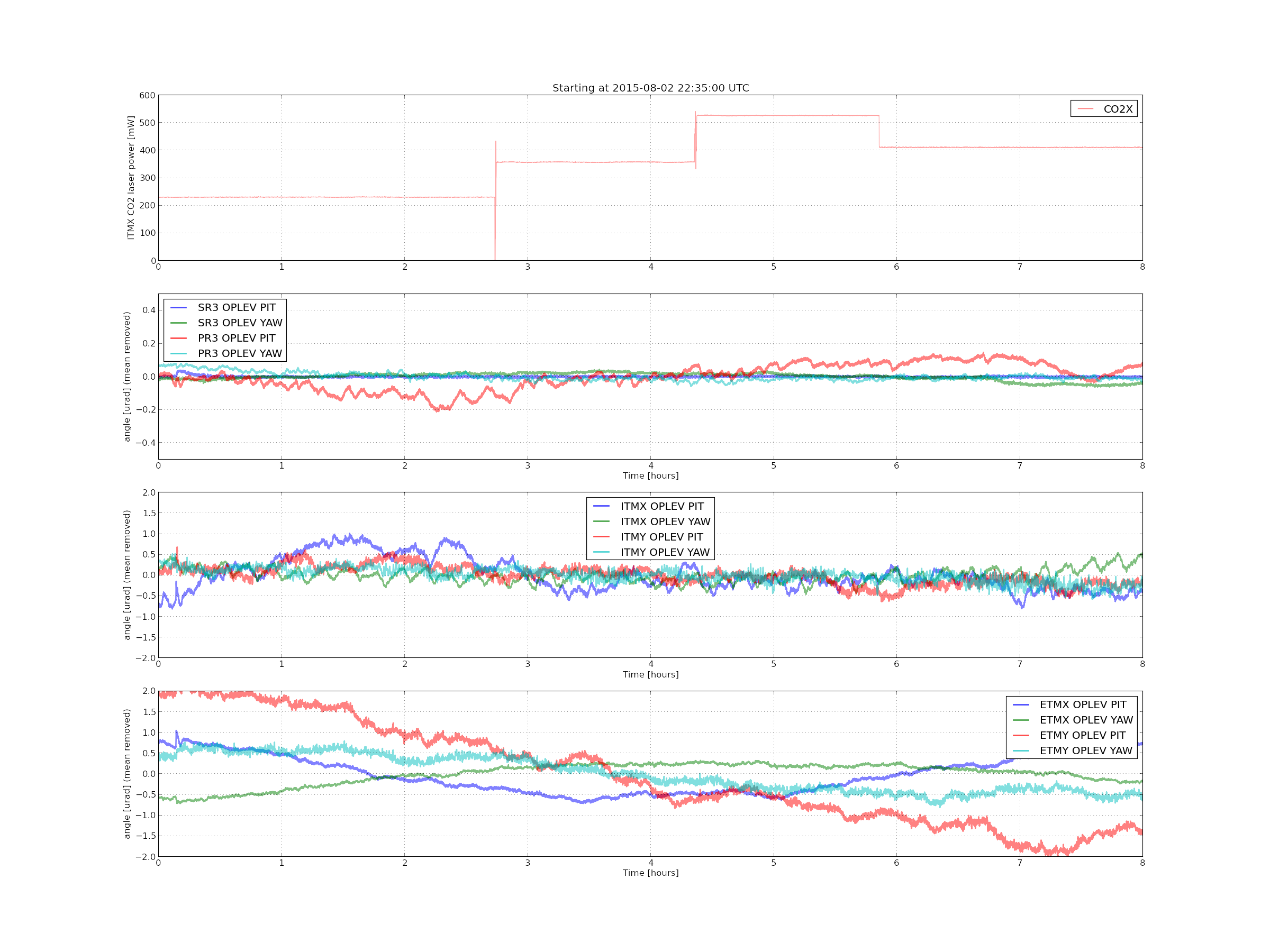
[3rd plot]
Since there was a suspicion that the frequency noise coupling may have been modulated by some misalignment, I plotted the optical lever signals which did not show a significant correction with the thermal steps that we made.