J. Kissel, B. Weaver, J. Driggers, R. McCarthy, D. Barker, D. Sigg, J. Batch
Here are the list of tomorrow's maintenance day tasks organized as we intend to execute them chronologically, and prioritized such that the tasks with the most global impact on the IFO are done first (such that we have the most time to recover from them). As with last Tuesday (LHO aLOG 19600), all tasks, associated estimated times for completion, and responsible persons (or "task manager") will be added to the reservation system when they are *actually happening*, and removed after the task manager has checked in with the operator and confirmed completion. PLEASE PAY ATTENTION TO THE RESERVATION SYSTEM (to help, we're going to put it on the big projector during maintenance).
As always, please keep the operators informed of your activities as accurately as possible / reasonable throughout the maintenance day so the reservation list can be adjusted accordingly and remain accurate. We appreciate your cooperation!
Group 0 -- prep for maintenance (to be done either the night before, or just before start of maintenance):
- Clear out all SDF system differences
- Ensure an alignment offset back up snap has been captured / define a reference time to which we will restore them
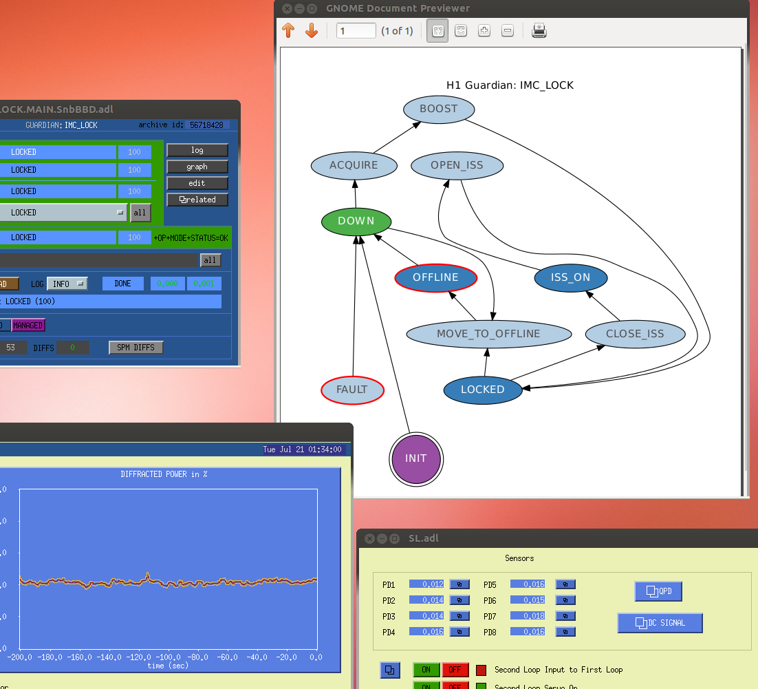
- Bring ISC_LOCK guardian to DOWN, Bring IMC_LOCK guardian to OFFLINE
- Bring all SEI manager guardians to OFFLINE
- Bring all SUS guardians to SAFE
Group 1 -- (tasks that can be performed simultaneously) to begin as soon as tasks dependent on group 0 are complete, otherwise, 08:00a PT
- Timing master's GPS reference swapped for external reference 30 min - 2 hours (R. McCarthy)
- We expect that this timing system swap will not glitch the timing system, and
therefore crash all front-ends, sitewide. However, we are preparing for the worst,
and bringing all systems to their respective DOWN / OFFLINE / SAFE state. HOWEVER if
the front-ends do crash, the recovery time will of order 2 hours to get all front-ends
back up and running. If not, we expect there to be little-to-no recovery time other than
to bring guardians back to their nominal states.
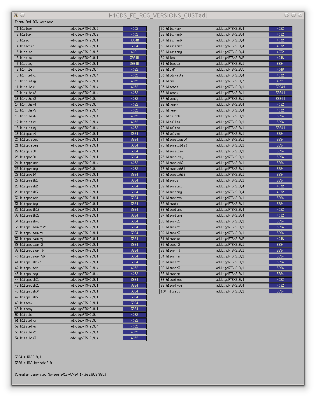
- IF AND ONLY IF the front ends do crash and we have to restart them, we will recompile
any front-ends that have crashed against RCG 2.9.6 in order to gather in the bug-fixes that
come with RCGs 2.9.1 through 2.9.6.
- HEPI Pump Station Repair 30 min (H. Radkins)
- Only one of four pump station appears noisey. The corner station can be run on only three
pump stations, so Hugh will merely ramp the errant pump out of the system and convert to
running the corner station on three pumps. This ramp out should only cause a brief minor
HEPI actuator pressure glitch. The 30 minutes is a conservative over-estimate of how long
it will take.
Group 1.5 -- can begin immediately after the effects of group 1 are known:
- Potential recompilation and install of the front-end models of all front-end machine's
that have crashed. See above 2 hours (J. Batch, D. Barker, J. Kissel)
- Cable routing / pulling for PEM Cosmic Ray Detector 2 hours (F. Clara, V. Roma, J. Palamos)
Recovery of corner station SEI / SUS, and relocking the IMC can begin upon assessment of effects of switching the timing master's GPS reference
Group 2 -- can begin while or after the corner station is being or has been recovered:
- PEM sensor calibrations 1 hour (V. Roma, J. Palamos)
- Replace / Repair Timing Fanout at EY 30 minutes (J. Batch, D. Barker)
- Upgrade BIOS on new EY SUS fast front-end 30 minutes (J. Batch, D. Barker)
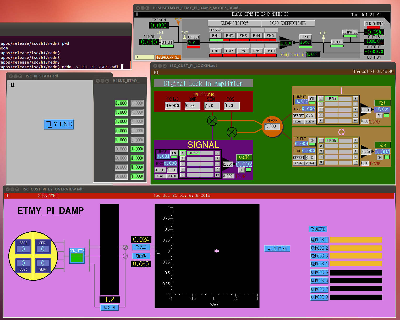
- EY SUS, EY Parametric Instability front-end models recompiled against RCG 2.9.6 and installed 30 minutes (J. Batch, D. Barker)
- EX Low-Voltage, Low-Noise driver installation and cabling 1 hour (R. McCarthy)
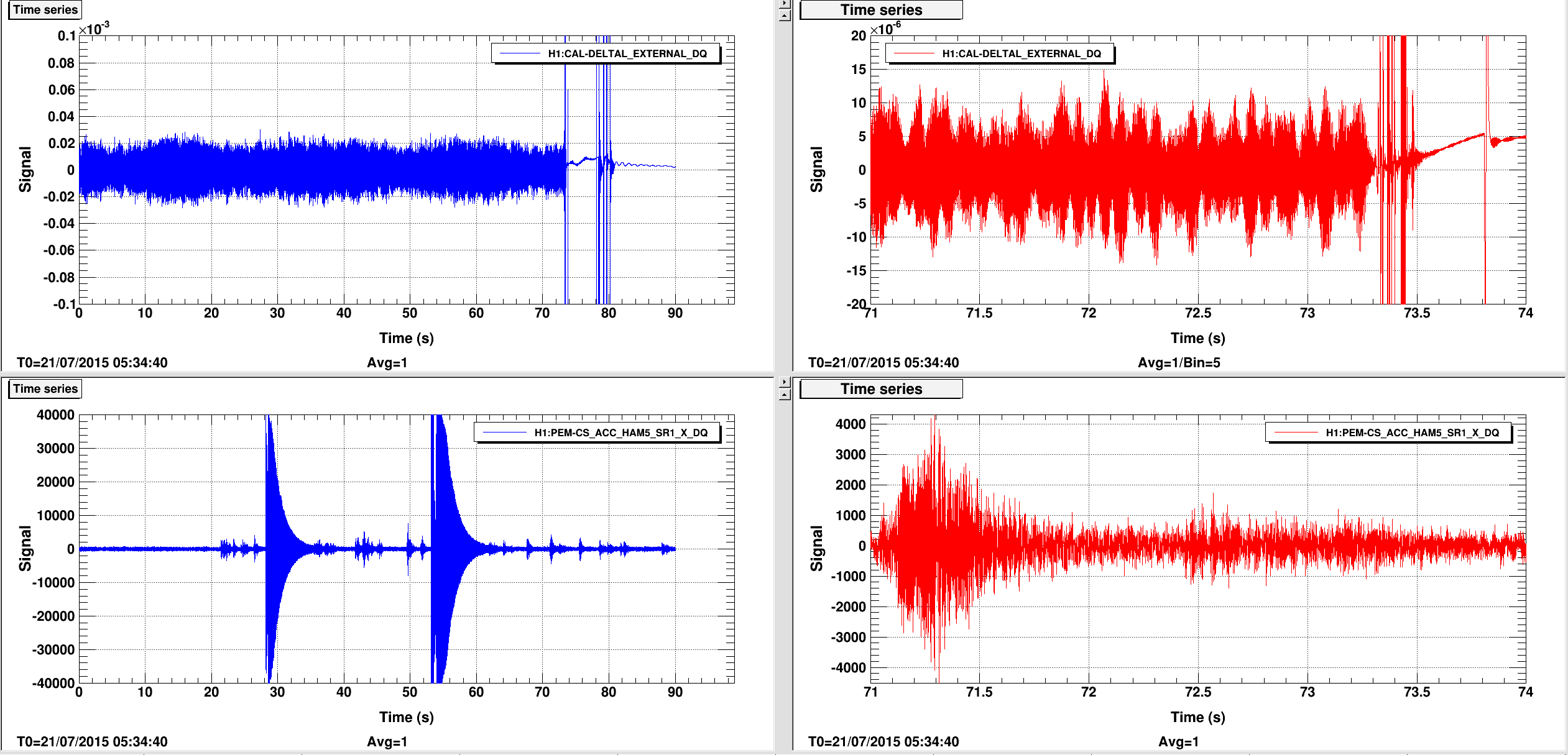
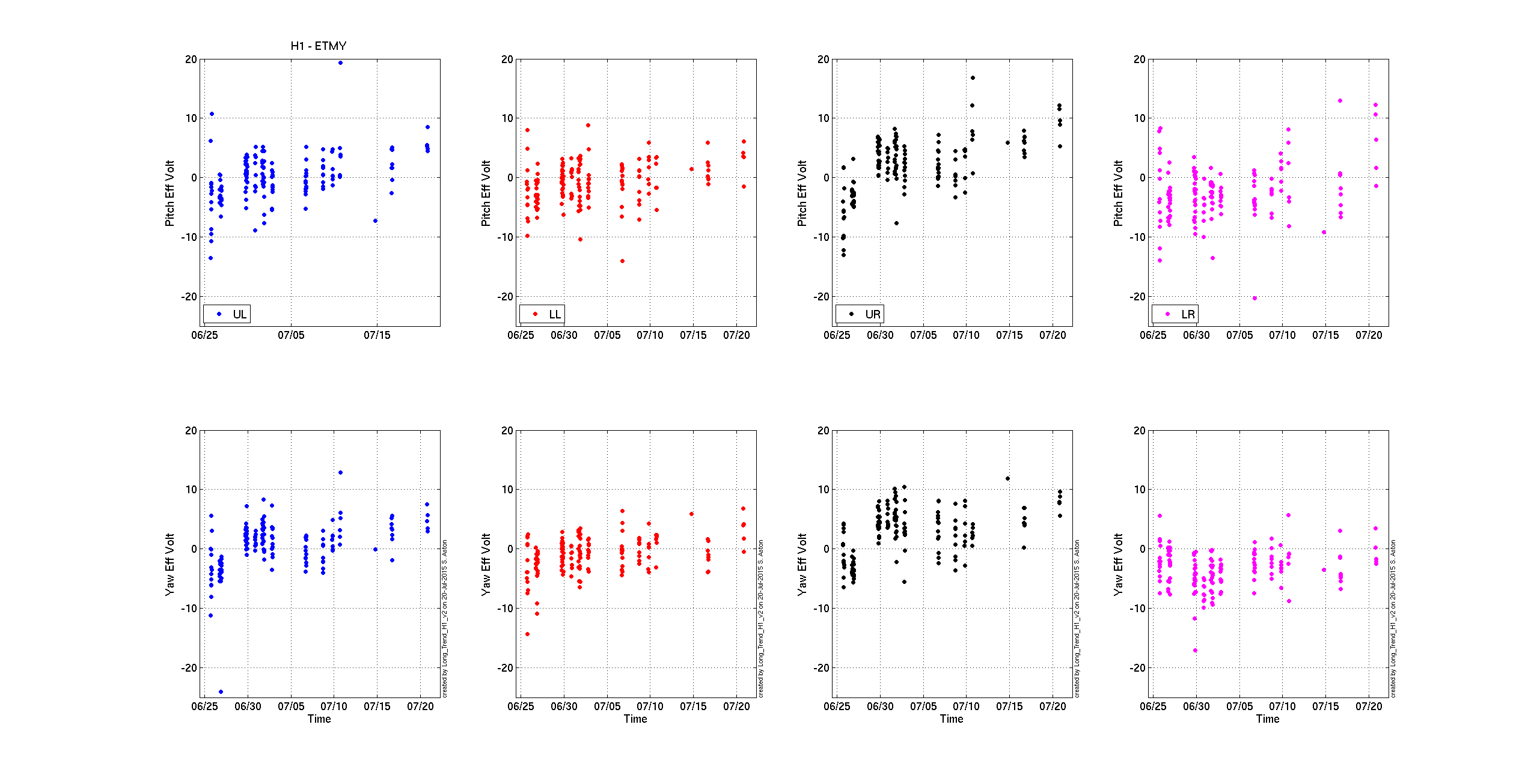
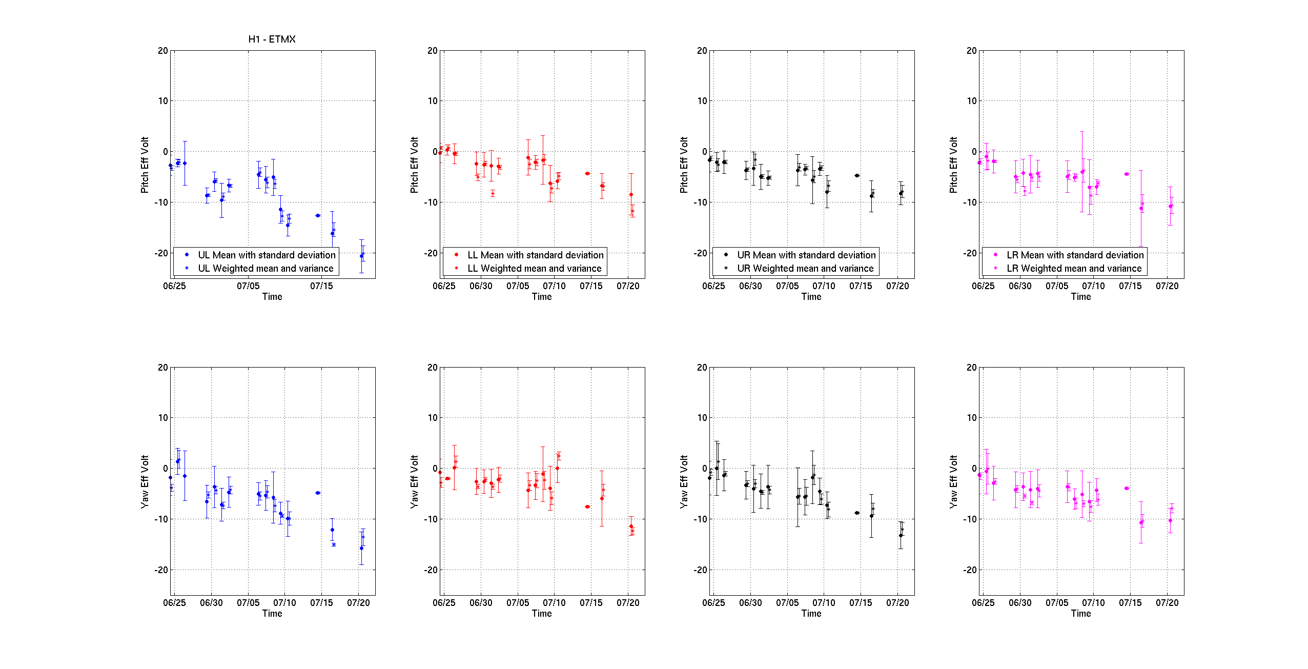
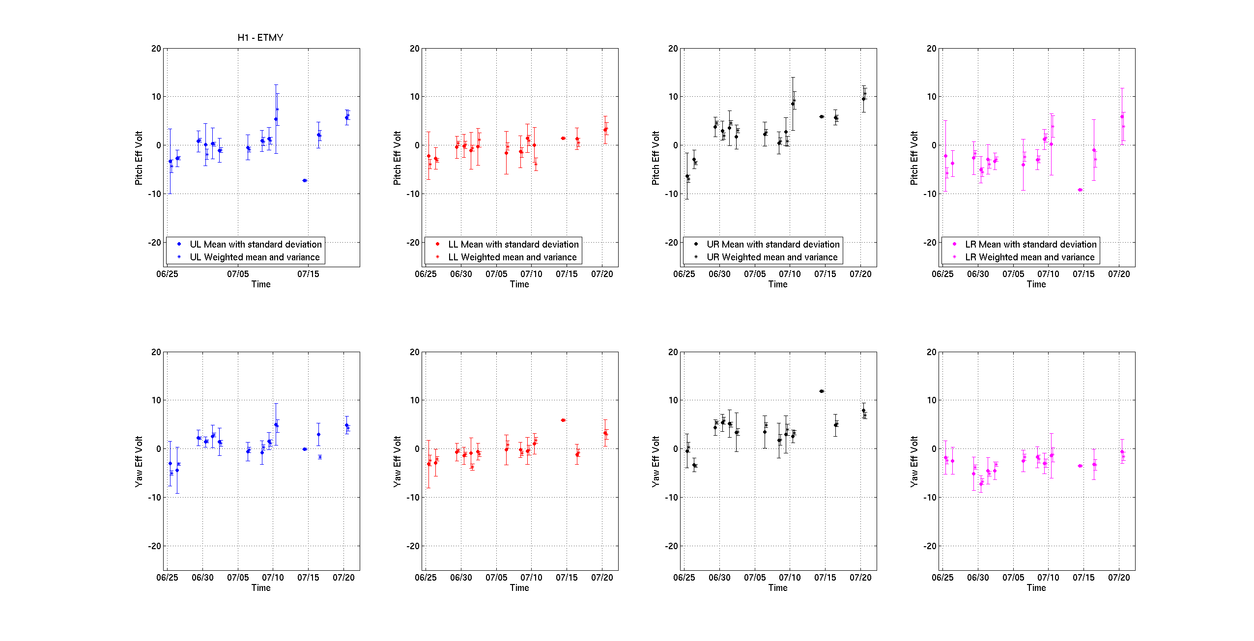
Recovery of all models at EY, restoration of settings, and bring up ETMY SEI / SUS, measure charge on ETMY SUS ESD to confirm ESD health
Group 2.5 -- can begin once work at EY is complete and/or while EY is being recovered:
- Upgrade BIOS on new EX SUS fast front-end 30 minutes (J. Batch, D. Barker)
- EX SUS, EX Parametric Instability front-end models recompiled against RCG 2.9.6 and installed 30 minutes (J. Batch, D. Barker)
Recovery of all models at EX, restoration of settings, and being up ETMX SEI/ SUS.
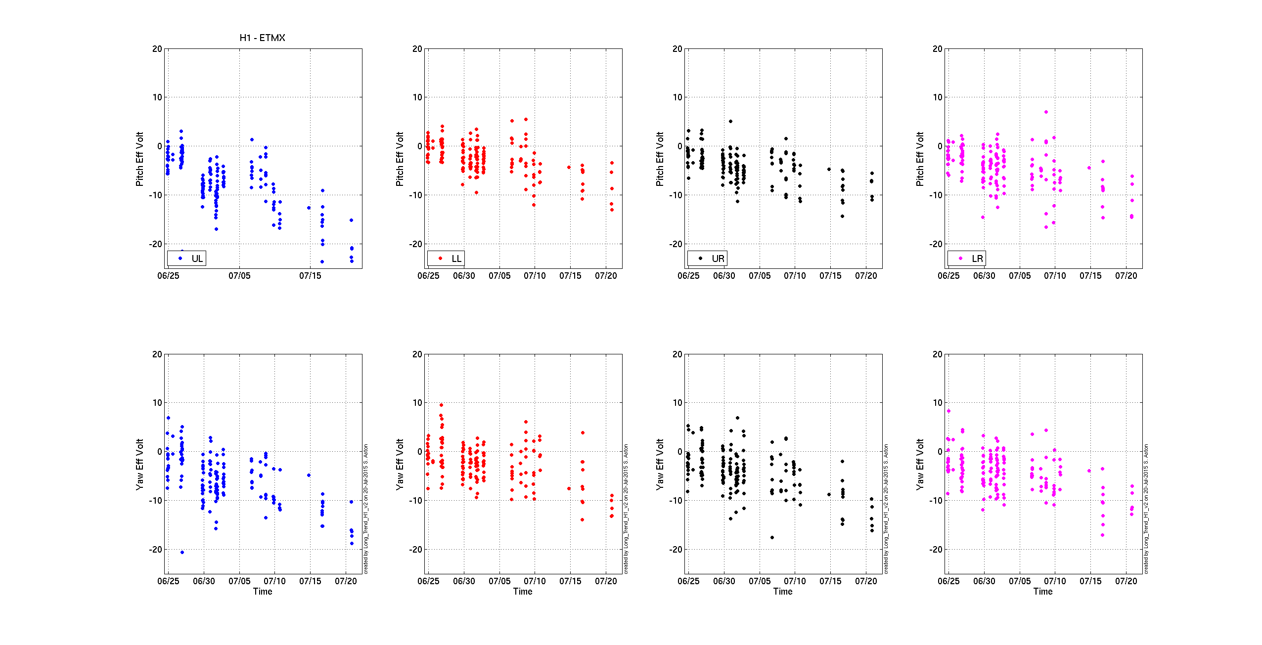
Confirm / commission the functionality of new ETMX LVLN ESD driver.
measure charge on ETMX SUS ESD to confirm ESD health.
Group 3 -- can begin once work and retoration at EX is finished
- Power cycle corner station front-end's network switch 10 minutes (J. Batch, D. Barker)
- Work stations will briefly loose their connection to the h1boot server, so workstations will be down briefly.
- Preventative maintenance reboots of the following computers
- Conlog
- EPICs gateway
- Guardian machine
Restoration of all alignment settings; recovery of FULL IFO can begin.
Group 3.5 -- can begin once workstations are back and preventative maintenance is complete.
- Rename and include Mid Station / Beam Tube PEM Accelerometers into PEM MX and MY front-end models 10 minutes (J. Batch, D. Barker)
- Parametric Instability monitor model install at EX 10 minutes (J. Batch, D. Barker)
- SUS AUX model upgrade 10 minutes (J. Kissel, B. Weaver)
- Fix LDAS communication fiber hardware 1 hour (J. Batch, D. Barker)
Complete IFO recovery and commission of new bits and pieces.
As seen last Tuesday, and many prior Teusdays, the above plan will not happen exactly as described above, as reality strikes. But, we will try our darnedest! Wish us luck!