Oli, Ibrahim, RyanC
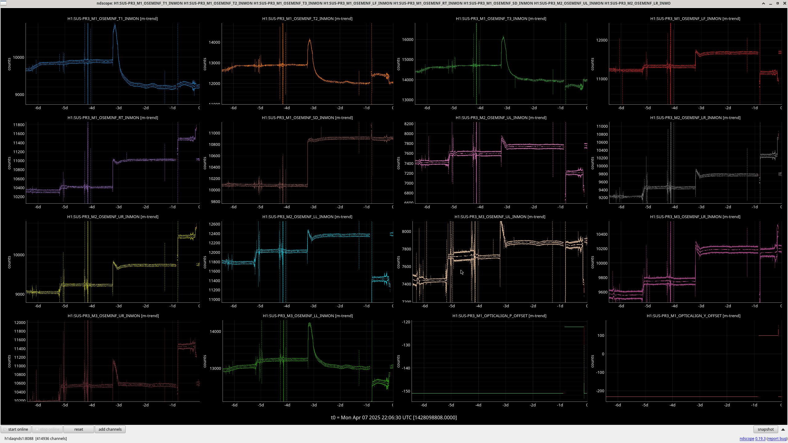
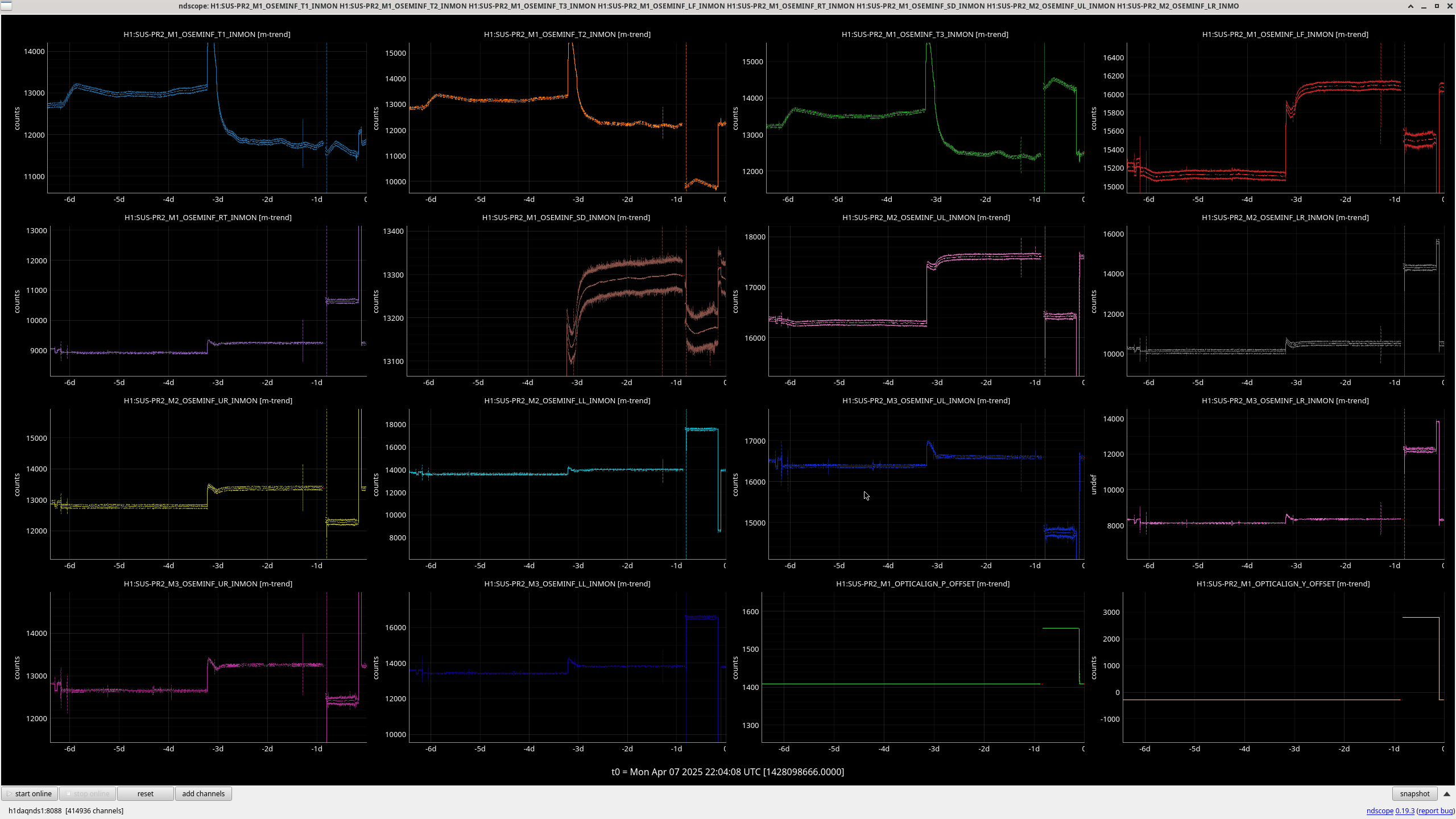
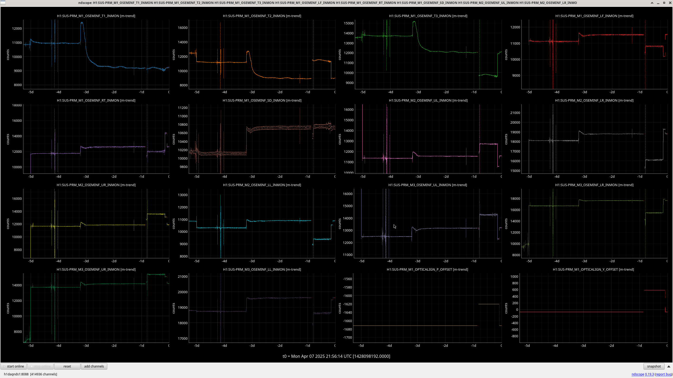
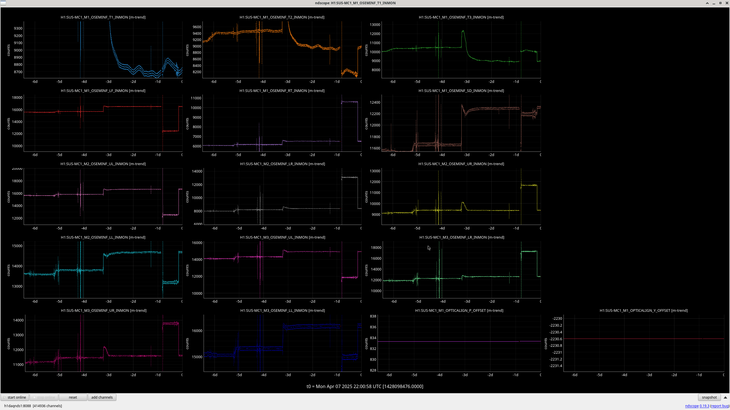
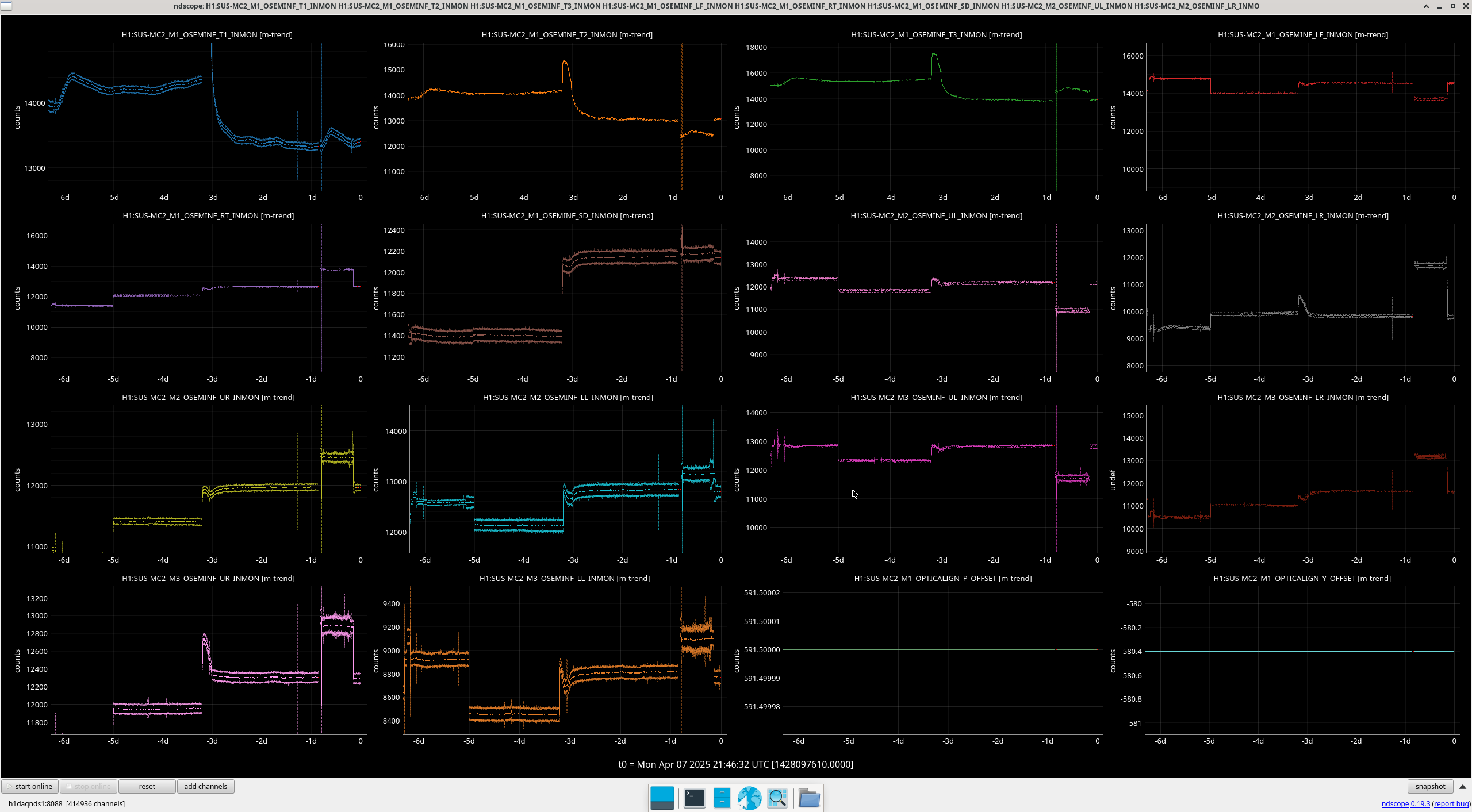
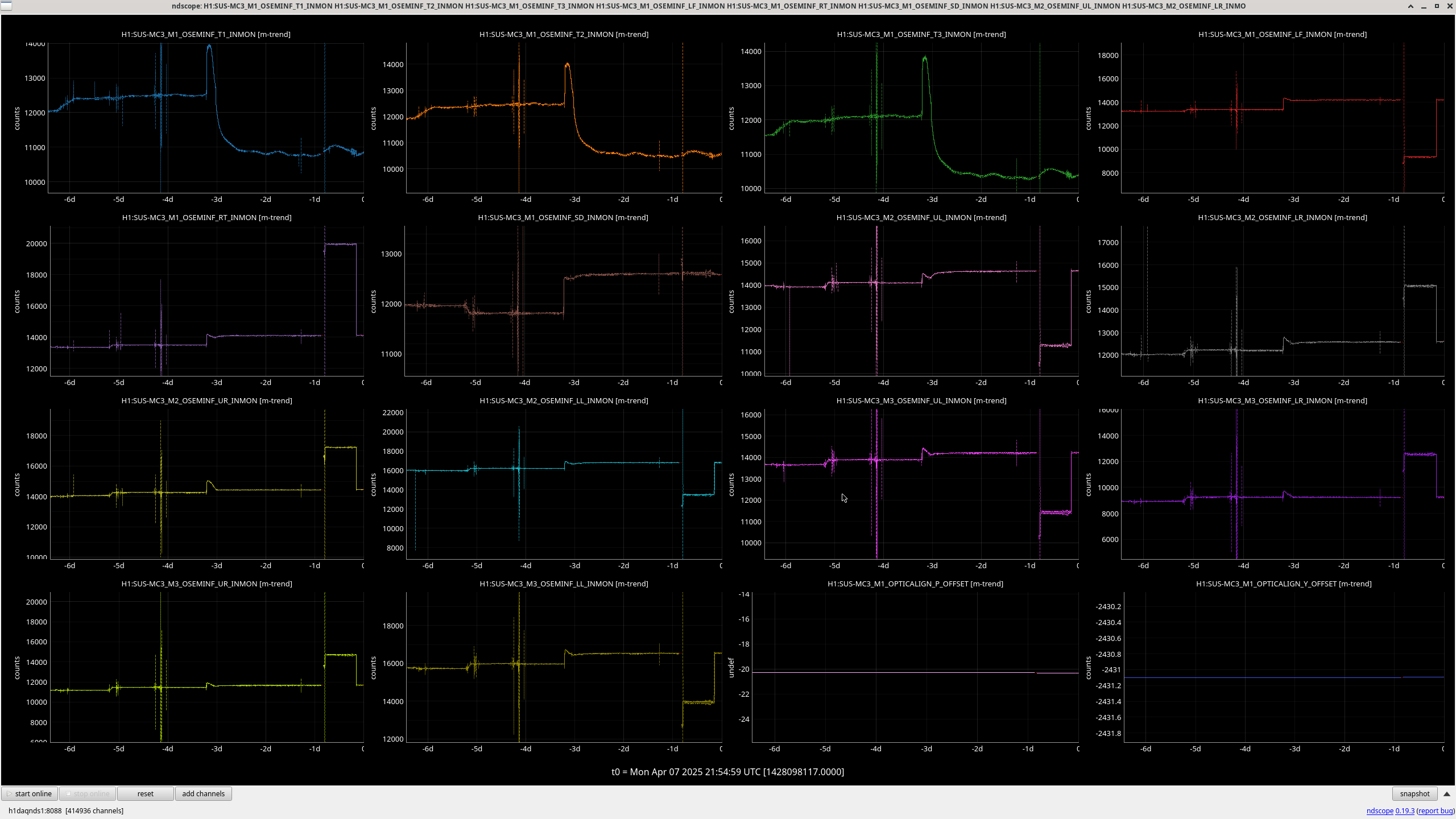
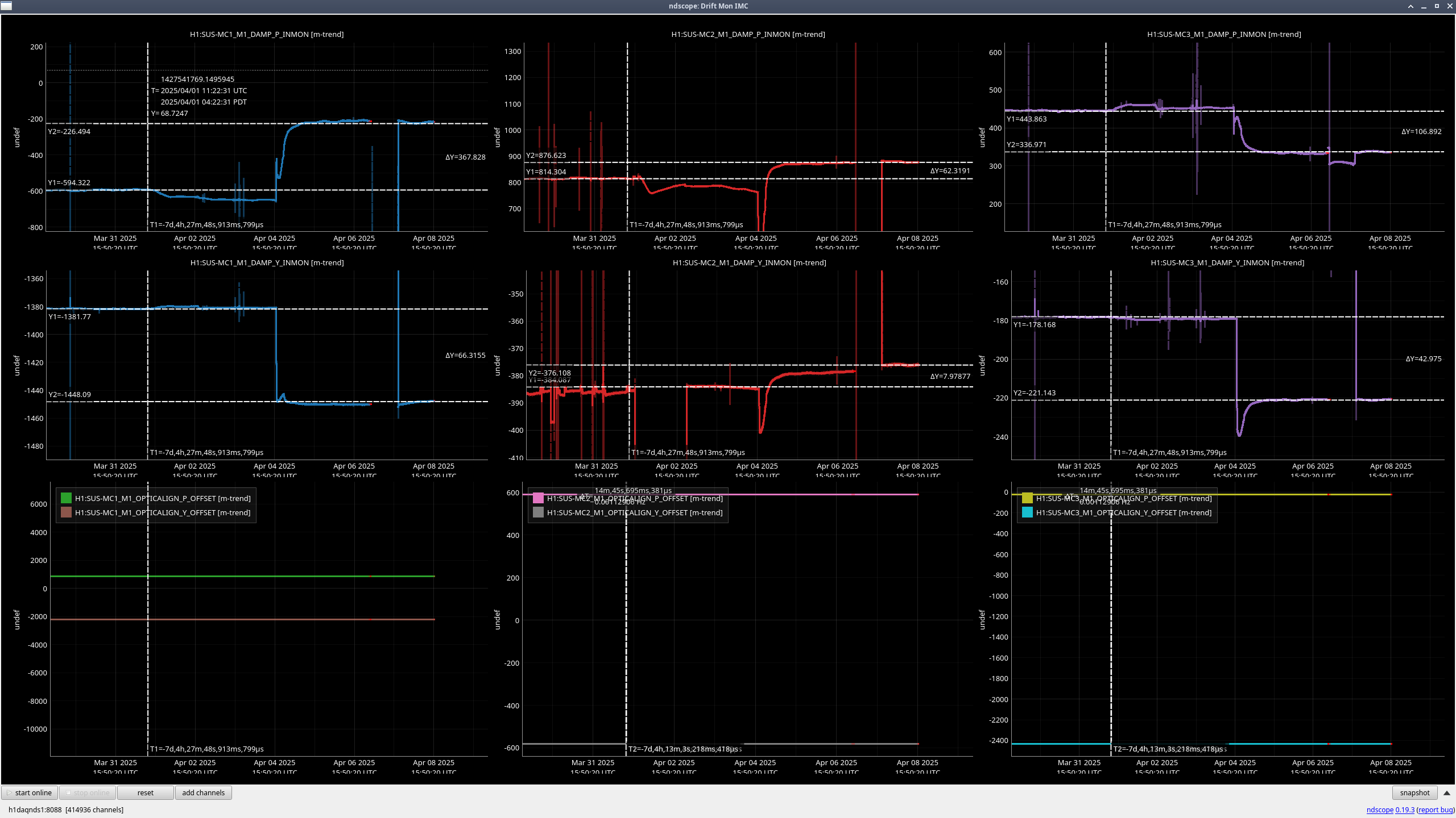
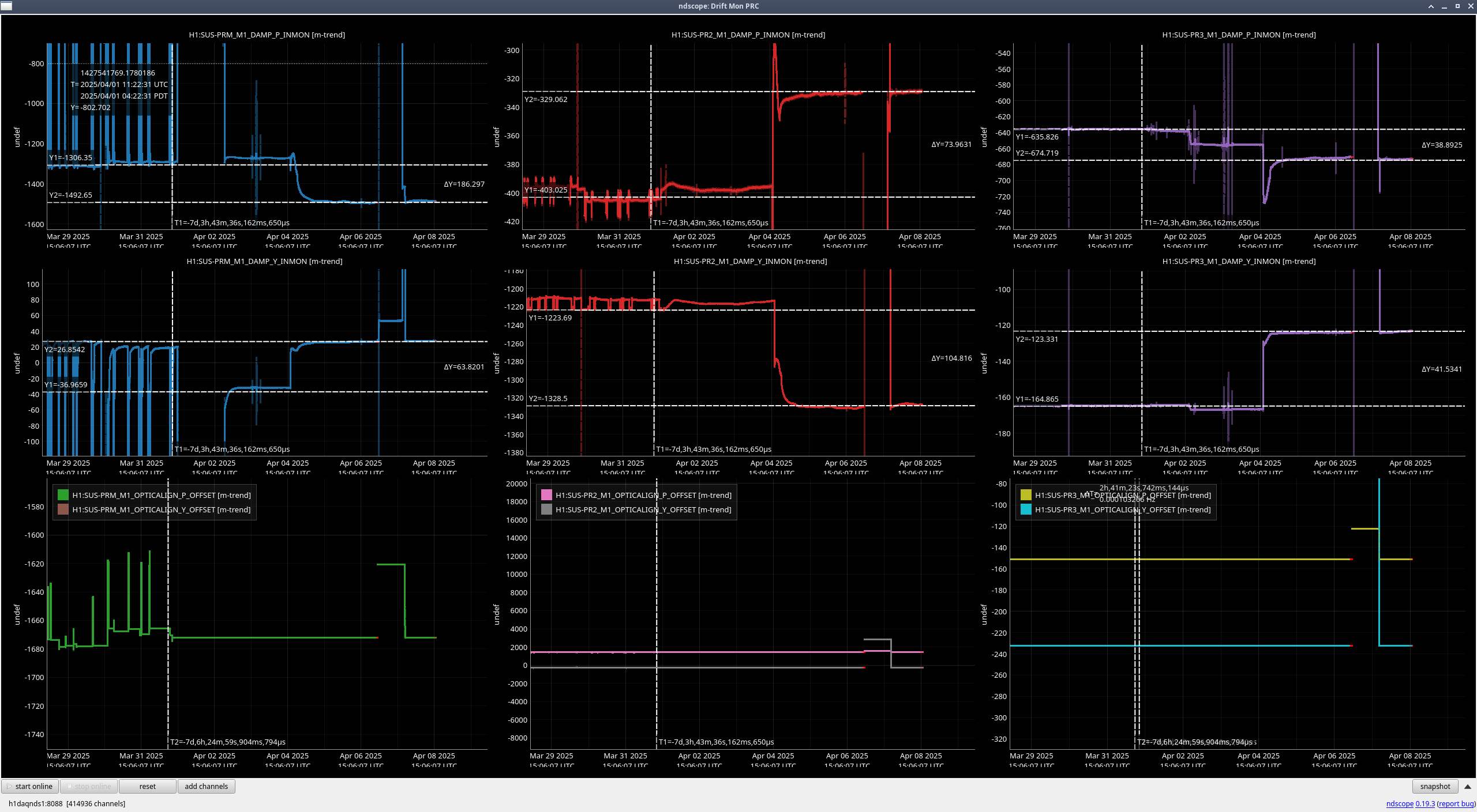
We took a look at the osems current positions for the suspensions post power outage to make sure the offsets are still correct, the previously referenced "Golden time" was 1427541769 (the last drmi lock before the vent). While we did compare against this time we mainly set them to before the poweroutage.
Input:
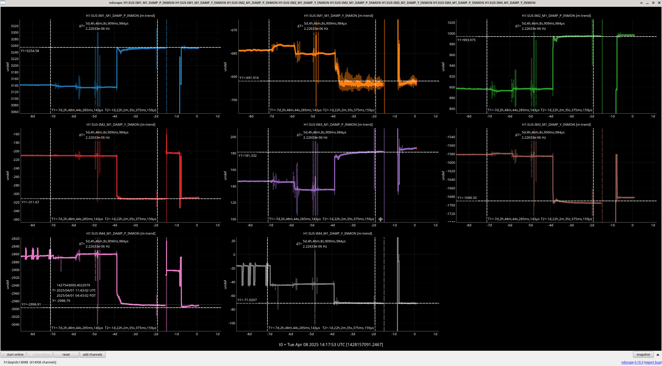
IM1_P: 368.5 -> 396.1, IM1_Y: -382.7 -> -385.4
IM2_P: 558.0 -> 792.0, IM2_Y: -174.7 -> -175.7
IM3_P: -216.3 -> -207.7, IM3_Y: 334.0 -> 346.0
IM4_P: -52.4 -> -92.4, IM4_Y: 379.5 -> 122.5
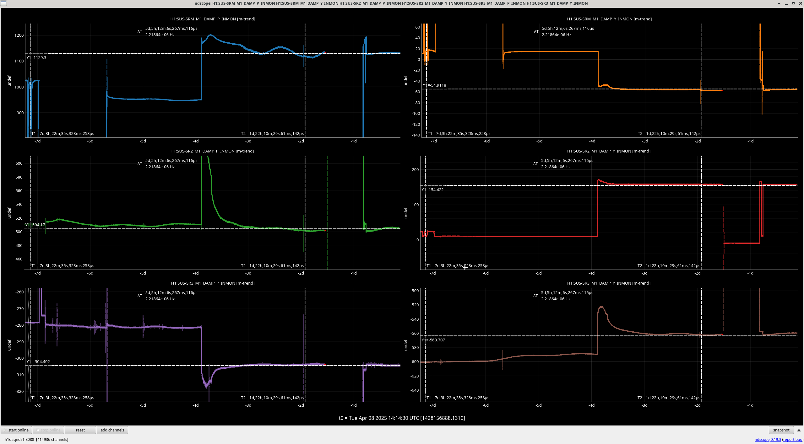
SR2_P: -114.3 -> -117.6, SR2_Y: 255.2 -> 243.6
SRM_P: 2540.3 -> 2478.3, SRM_Y: -3809.1 -> -3825.1
SR3_P: 439.8 -> 442.4, SR3_Y: -137.7 -> -143.9
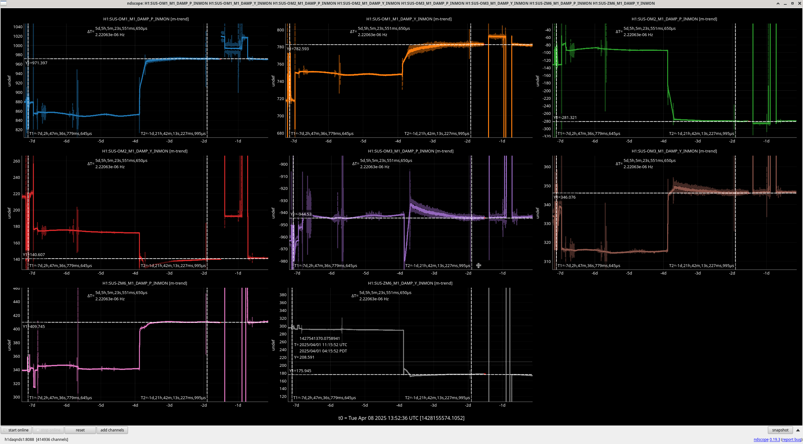
Output:
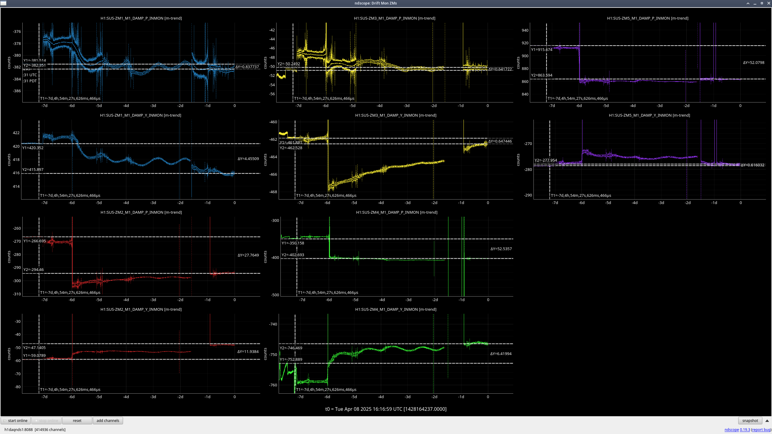
ZM6_P: 1408.7 -> 811.7, ZM6_Y: -260.1 -> -206.1
OM1_P: -70.9 -> -90.8, OM1_Y: 707.2 -> 704.5
OM2_P: -1475.8 -> -1445.0, OM2_Y: -141.2 -> -290.8
OM3_P: Didn't adjust, OM3_Y: Didn't adjust