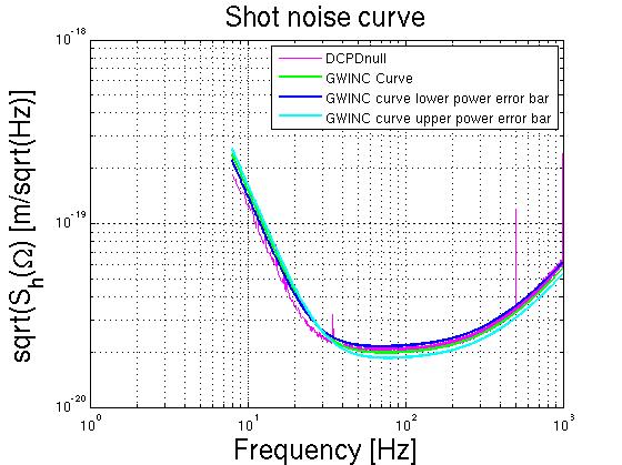
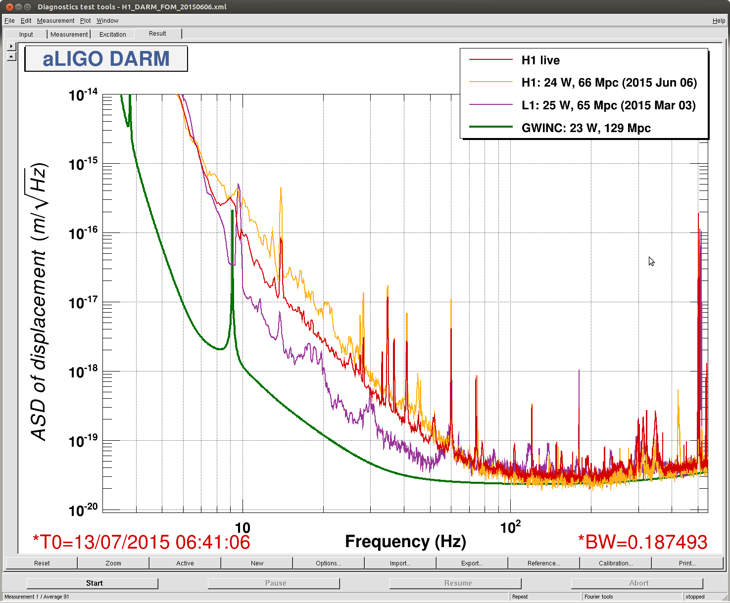
Displaying reports 69121-69140 of 83107.Go to page Start 3453 3454 3455 3456 3457 3458 3459 3460 3461 End
Reports until 10:25, Thursday 09 October 2014
H1 AOS (DetChar)
sheila.dwyer@LIGO.ORG - posted 10:25, Thursday 09 October 2014 - last comment - 09:07, Friday 14 November 2014(14381)
etmx oplev glitches

Jason, Sheila

There have been some glitches on the ETMX oplev, which don't seem to correspond to motion of the optic, the attached screen shot shows an example.  I think that I have seen glitches like this that were much larger in amplitude, but am not sure. 

One question for detchar is if they have a tool that can search for glitches like these, and give us some information about how often they are happening, how large they are, and maybe monitor to see if they are happening on other op levs

Another issue is that sometimes the lasers fail, which is often foretold by a several seconds oscillation in the oplev sum.  Can detchar set up some kind of monitoring for that?

Of course the real question is how can we fix it......

Images attached to this report
Comments related to this report
shivaraj.kandhasamy@LIGO.ORG - 14:40, Friday 10 October 2014 (14406)DetChar

Hi Jason and Sheila, here at LLO  Olmo Cerri, a summer student from UMISS, looked at the possible causes of glitches in OPLEVs. He worked with Suresh. Suresh earlier found that the the temperature variation could cause changes in the cavities of OPLEV laser and thereby changing the laser intensity which would look like glitches. Olmo looked at week long strecthes of data from a few OPELVs and charactersized how many glicthes we see (he wrote a matlab script to find the such gltiches).  They also implemetned a simple temperature stabilization method (LLO a-log) to reduce the gltiches. It seemed to work well. Here is a presentation by  Olmo on this work which shows data before and after the temperature stabilization setup. He is now looking into implemneting an online version of the code.

cody.arceneaux@LIGO.ORG - 09:07, Friday 14 November 2014 (15053)
I set Olmo's code to run on a cron job with the results here:

https://ldas-jobs.ligo-wa.caltech.edu/~codyca/MHoF_results/

We still need to put together a better way to present the results.  The code is set to remove glitches caused by human interaction by looking at the OPTICALIGN offsets.  Also, the results for LLO can be found here:

https://ldas-jobs.ligo-la.caltech.edu/~codyca/MHoF_results/
H1 SEI
hugh.radkins@LIGO.ORG - posted 09:06, Thursday 09 October 2014 (14380)
WBSC2 BS ISI Guardian 'NOMINAL' updated to 'green' the notifications

Awaiting discussion with JRollins before committing to svn.

H1 ISC
sheila.dwyer@LIGO.ORG - posted 20:24, Wednesday 08 October 2014 (14378)
DRMI asc today

Before the earth quake hit us tonight, (magnitude 6.8 in the pacific) we worked on ASC for DRMI.  We started out using PRMI, but since our DRMI lock was much more stable today than it had been last night, we switched to just locking DRMI.  We suceeding in closing two loops from REFL 9 A to PRM, for PIT we used a gain of -1e-4 for yaw we used a gain of 1e-4.  Then the earth quake hit, now all 4 test mass ISIs are tripped. 

H1 General
jim.warner@LIGO.ORG - posted 16:43, Wednesday 08 October 2014 (14375)
Daily summary

9:15 Krishna & Richard to EX ground BRS
9:15 Jason & Doug to LVEA, cleaning up IAS equipment
13:30 Gerardo & PK to h2 laser enclosure
14:15 Jeff B to LVEA suspensions work done at 15:30
 

H1 SEI
hugh.radkins@LIGO.ORG - posted 14:05, Wednesday 08 October 2014 - last comment - 14:41, Wednesday 08 October 2014(14373)
LHO SEI Cartesian Basis Status

The local sensors, both positional and inertial, are converted to Ligo Global Frame (assuming the ZL & ZG are collocated, which they are not, quite) via calibration filters and local to cartesian transformation matrices; this is done using the right hand rule, RHR.  Many of the platforms for H1 were commissioned before much thought and diligence was put into these matrices.  The seismic group has finalized these transforms and we can now correct the long standing errors. However, this will require taking platforms off line to load the matrices as well as new cartesian basis controllers and Position Targets for many of the platforms.  We'll attempt to do this systematically during maintenance days and other opportunities.

Meanwhile, as I just finished an update to the state of these matrices, I thought a tabulation of the platforms was in order.

  HEPI Impact ISI Impact

HAM1

Wrong Magnitudes are correct so displacements are right but the rotational dofs have the wrong sign wrt RHR. NA iLIGO Platform
HAM2 Wrong Ditto Wrong Rotational dof signs are wrong for RHR
HAM3 Wrong Ditto Wrong Ditto
HAM4 Correct Signs & Amplitudes are right for examining platform movement Wrong CPS & GS13 matrices are good, correcting L4C2CART will not impact platform or alignment
HAM5 Correct Ditto Wrong Ditto
HAM6 Correct Ditto Wrong Ditto
ITMY Wrong X & Y dof mags wrong. ~x2 Wrong All good sans HEPI L4C Sencorr--no impact on use of sensors.
BS Wrong Rotation dof mags are incorrect, RZ x4, RX & RY x2 Wrong X Y RX & RY signs are wrong putting positional study in jeopardy
ITMX Correct Signs & Amplitudes are right for examining platform movement Wrong All good sans HEPI L4C Sencorr--no impact on use of sensors.
ETMX
ETMY
Correct
Correct
Ditto
Ditto
Wrong
Wrong
X Y RX & RY signs are wrong putting positional study in jeopardy
Minor errors in off diag elements, basic study use okay but fixing will require completesweep through system.
Comments related to this report
jeffrey.kissel@LIGO.ORG - 14:41, Wednesday 08 October 2014 (14374)
Awesome summary, thanks Hugh!

For everyone else, 
- The document where we define the local-to-cartesian basis transformation that Hugh refers to is T1000388. 
- Orientations of Cartesian bases with respect to the global IFO coordinates are defined in G1000125. 
- Finally, the document that defines the calibration of each sensor is D1001575.

For the record, when Hugh says "Mags," "Magnitude," or "Amplitude," he means the same thing, and that's the value of the elements in the above mentioned matrices. Also "displacements" means translations, i.e. X, Y, Z, and "positional study," "platform movement," and "platform" and means performance of the given stage. Rotational DOFs, and "alignment" are the same thing: RX, RY, and RZ.

(These are all linked together in E1300815, "the SEI Controls Document Hub," E1100703, and also "Useful Documents for SEI Testing and Commissioning," both linked from the aLIGO, SEI document tree E1200684.)
H1 ISC
keita.kawabe@LIGO.ORG - posted 12:30, Wednesday 08 October 2014 - last comment - 19:02, Wednesday 08 October 2014(14371)
Green WFS with ITMY camera centering servo works

Summary: It works consistently without remeasuring the sensing matrix everyday and some other nonsense.

The current setup (which will change in the future) is this:

The screen shot shows the current settings.

Other things:

In the same screen shot, the strip tool shows that the demise of the WFS centering is the demise of this system. Blue trace is one of the outputs of the WFS centering, and as soon as it starts to hit the bottom rail everything becomes ratty and eventually it breaks lock. I'll change the table layout to get more juice out of the PZT mirror range.

When it unlocks, a large transient from the centroid thing hits both ETMY and ITMY, so you need to wait for maybe 30 seconds until it becomes possible to lock again.

You want to reset the WFS centering servo (which may or may not grab) and enable the WFS again, and most of the time it goes back to a good alignment. Sometimes WFS centering never recovers by this procedure. If that happens, you might want to zero the ASC output to the ETMY and ITMY and do it again.

Images attached to this report
Comments related to this report
peter.fritschel@LIGO.ORG - 19:02, Wednesday 08 October 2014 (14377)

Very promising -- that's great.

H1 SEI
hugh.radkins@LIGO.ORG - posted 10:13, Wednesday 08 October 2014 (14369)
CPS Ground Straps added to WBSC1 ITMY

Yesterday I surveyed the CPS grounding systems and found the ITMY racks lacking anything explicit.  There is of course, in theory, grounding by virtue of the rack sitting directly on the unistut attached to the chamber.  However, as per T1300871, the grounding is expected to be from the board 'Target Ground' lugs to the chamber.  At noon yesterday, I added this to the three BSC1 CPS racks.

Below is spectra from Tuesday am and Wednesday am so a before and after view.  The Blends are in the same state (PCOMM JimW) and we are in all ways, in the same configuration.  The ground motion could be different of course.

Images attached to this report
LHO General (SUS)
rainer.weiss@LIGO.ORG - posted 10:01, Wednesday 08 October 2014 (14368)
Significant puzzle in explaining the charging mechanism of the test masses
Please look at the attached pdf file.
Non-image files attached to this report
H1 CDS (DAQ)
david.barker@LIGO.ORG - posted 09:53, Wednesday 08 October 2014 (14367)
CDS model and DAQ restart report, Tuesday 7th October 2014

model restarts logged for Tue 07/Oct/2014
2014_10_07 08:44 h1iscey
2014_10_07 08:54 h1iscey
2014_10_07 09:07 h1iscey
2014_10_07 09:10 h1asc
2014_10_07 09:21 h1iscex
2014_10_07 09:35 h1asc
2014_10_07 09:35 h1iscex
2014_10_07 09:35 h1iscey
2014_10_07 11:05 h1calex
2014_10_07 11:05 h1iopiscex
2014_10_07 11:05 h1iscex
2014_10_07 11:05 h1odcx
2014_10_07 11:05 h1pemex

2014_10_07 11:59 h1broadcast0
2014_10_07 11:59 h1caley
2014_10_07 11:59 h1dc0
2014_10_07 11:59 h1fw0
2014_10_07 11:59 h1fw1

2014_10_07 11:59 h1iopiscey
2014_10_07 11:59 h1iscey

2014_10_07 11:59 h1nds0
2014_10_07 11:59 h1nds1

2014_10_07 11:59 h1odcy
2014_10_07 11:59 h1pemey
2014_10_07 12:39 h1iopiscey
2014_10_07 12:41 h1caley
2014_10_07 12:41 h1iscey
2014_10_07 12:41 h1odcy
2014_10_07 12:41 h1pemey
2014_10_07 12:45 h1iopiscex
2014_10_07 12:47 h1calex
2014_10_07 12:47 h1iscex
2014_10_07 12:47 h1odcx
2014_10_07 12:47 h1pemex

2014_10_07 12:48 h1broadcast0
2014_10_07 12:48 h1dc0
2014_10_07 12:48 h1fw0
2014_10_07 12:48 h1fw1
2014_10_07 12:48 h1nds0
2014_10_07 12:48 h1nds1

2014_10_07 13:04 h1pemex
2014_10_07 13:06 h1pemey

2014_10_07 13:08 h1dc0
2014_10_07 13:08 h1fw0
2014_10_07 13:08 h1fw1
2014_10_07 13:08 h1nds0
2014_10_07 13:08 h1nds1
2014_10_07 13:12 h1broadcast0

2014_10_07 14:56 h1calex
2014_10_07 14:56 h1iopiscex
2014_10_07 14:56 h1iscex
2014_10_07 14:56 h1odcx
2014_10_07 14:56 h1pemex

2014_10_07 15:02 h1iopsusex
2014_10_07 15:02 h1susetmx
2014_10_07 15:02 h1sustmsx
2014_10_07 15:06 h1hpietmx
2014_10_07 15:06 h1iopseiex
2014_10_07 15:06 h1isietmx

2014_10_07 15:35 h1calex
2014_10_07 15:35 h1iopiscex
2014_10_07 15:35 h1iscex
2014_10_07 15:35 h1odcx
2014_10_07 15:35 h1pemex

No unexpected restarts. A busy maintenance day. Daniel's ASC and ISC model changes. Addition of CAL models to end station ISC. Recovery of EX SEI and SUS after accidental crash. Associated DAQ restarts.

H1 PSL (IOO)
kiwamu.izumi@LIGO.ORG - posted 02:57, Wednesday 08 October 2014 (14360)
FSS was oscillating. common gain decreased temporarily

Sheila, Alexa, Kiwamu,

We noticed that occasionally the IMC locking loop kicks the FSS into a situation where the FSS oscillates for unknown reason.

We did not check what frequency the oscillation was, but this was visible in the PZT monitor in the FSS screen. It kept oscillating even after the IMC feedback onto FSS was disabled. We figured out that decreasing the common gain somehow fixes the oscillation. Strangely,  once the oscillation was gone, we could set the common gain back to the nominal of 30 dB without the oscillation. We believe that this oscillation is a part of the reason why the IMC did not recover right away when it looses the lock.

For the commissioning tonight, we reduced the common gain to 18.8 dB.

H1 AOS
kiwamu.izumi@LIGO.ORG - posted 02:46, Wednesday 08 October 2014 - last comment - 12:55, Wednesday 08 October 2014(14359)
more DRMI -- 3f locked, ASC loops being closed

Sheila, Kiwamu,

Our focus tonight were:


(DRMI 3fs are now stable)

We succeeded in transitioning to the 3f signals in DRMI. We checked the demodulation phase of  REFLAIR_RF135 by exciting SRM and BS at a time. A good demod phase was found to be 56 deg while it had been -2.7 deg since the last week (see alog 14268). This demod phase was the one in which the SRCL signal is minimized in 135_Q. The resultant input elements are:

I have not measured the open loop transfer functions yet, but so far I did not see a gain peaking. The SRM M2 stage coil output had an rms counts of about 1x10⁴ which is very OK in terms of the DAC saturation. I did not get a chance to see its long term stability. The ISC_DRMI guardian is edited accordingly and we confirmed that the guardian could transition to the 3fs automatically. Note that I enabled two whitening stages in REFLAIR_RF135. This saturates the ADC until the DRMI is locked, but once it is locked, the saturation does not seem to happen any more.

(some attempts on ASC loops)

For some reason, the SRCL mode-hop happened frequently tonight, even though the alignment was not too bad -- both PRC and SRC sideband power could fluctuate as small as a few % depending on misalignment which of course evolves on a time scale of order of 10 sec. So we decided to close the ASC loops rather than manually aligning the optics. We started from MICH which is ongoing.

Comments related to this report
sheila.dwyer@LIGO.ORG - 12:55, Wednesday 08 October 2014 (14372)

Early in the evening last night we could not lock the input beam to the X arm (because of a maintence day snafu), and skipped this step of our inital alingment.  Although the pointing down the arm seemed OK based on the flashes that we saw, it was actually not good.  We then tried our inital alingment steps of PRX with refl wfs, which didn't work.

Once we had recovered the ETMX ISI we redid the intial alingment process from the begining, and it worked well resulting in a good alingment for DRMI locking.  

H1 SUS
kiwamu.izumi@LIGO.ORG - posted 23:46, Tuesday 07 October 2014 - last comment - 09:08, Wednesday 08 October 2014(14357)
SRM M0 stage sensor is not healthy

sad

There is a huge peak at 60 Hz in the damping singals on M0 of the SRM suspension. Also the noise floor seems too high compared with PRM. This must be fixed.

Images attached to this report
Comments related to this report
sheila.dwyer@LIGO.ORG - 00:25, Wednesday 08 October 2014 (14358)

This has been this way for a long time....

Images attached to this comment
jeffrey.kissel@LIGO.ORG - 09:08, Wednesday 08 October 2014 (14366)
Not that it should be prevent looking for and solving the problem, but this is most likely related to Integration Issue 935, see original discovery aLOG LHO aLOG 13556.

Richard will be looking at it this morning, potential cutting ex-vacuo cabling to try to fix this known in-vac problem.
H1 CDS (DAQ, ISC)
david.barker@LIGO.ORG - posted 16:45, Tuesday 07 October 2014 - last comment - 07:56, Wednesday 08 October 2014(14345)
Install of new CAL models at both end stations on the ISC front end computers

Cyrus, Jim,  Rick, Shivaraj, Dave

WP4888

Two new H1 front end models were created, h1calex and h1caley. They run on the end station ISC front ends, using the 4th user-model core. We assigned them the next two spare DCU-IDs  (h1calex=124, h1caley=125).

The cal models currently only have the PCAL subsystems. I took the latest version of the PCALX code from h1odcx (where it was temporarily installed for testing) and installed on both end stations. The models' channels have the prefix H1:CAL-PCAL[X,Y]_. The CAL models are located under SVN in the ISC path (isc/h1/models/h1cale[xy])

The CAL models use the first ADC because they require the DUOTONE timing signals. The PEM models were modified to use the 4th ADC. The ISC models continue to use the 2nd and 3rd ADC and did not need modification.

The CAL models use the newly installed 18bit DAC card. This card is also used by the PEM model to drive unused channels (I modifed PEM accordingly).

The DAQ master and H1EDCU_DAQ.ini files were modified to include the new CAL models.

The IOP models h1iopisce[xy] were modifed to add the 4th ADC and 18bit DAC.

All models on the ISC front ends and the DAQ were restarted several times during this install.

Here is a summary list of model changes

h1iopiscex add ADC and 18bit DAC
h1iopiscey add ADC and 18bit DAC
h1pemex switch ADC from 1st to 4th and add 18bit DAC, filter modules to drive unused DAC channels
h1pemey switch ADC from 1st to 4th and add 18bit DAC, filter modules to drive unused DAC channels
h1odcx remove PCALX part from this model
h1calex New CAL EX model. Uses 1st ADC and 18bit DAC (first channel)
h1caley New CAL EY model. Uses 1st ADC and 18bit DAC (first channel)
Comments related to this report
david.barker@LIGO.ORG - 07:56, Wednesday 08 October 2014 (14363)

The CDS overview MEDM screens (large and small) were modified to include the new end station CAL models. Also the h1oaf0 was modified to put in place holders for the GAMMACAL and CALCS models which will be installed soon.

H1 ISC
daniel.sigg@LIGO.ORG - posted 13:44, Tuesday 07 October 2014 - last comment - 11:38, Wednesday 08 October 2014(14341)
ITMY green camera setup

Reloaded the iscex/ey and asc models to enable the new camera channels.

The attached snap shows

When the Y-arm is locked on green this should now give an error signal to the green alignment system.

Images attached to this report
Comments related to this report
keita.kawabe@LIGO.ORG - 11:38, Wednesday 08 October 2014 (14370)

The script didn't work until I swapped H1:VID-CAM24_X and H1:VID-CAM24_Y:

#!/bin/bash
while [ true ]; do
        ezcawrite H1:ALS-Y_CAM_ITM_PIT_POS 'ezcaread H1:VID-CAM24_Y|awk '{print $3}''
        ezcawrite H1:ALS-Y_CAM_ITM_YAW_POS 'ezcaread H1:VID-CAM24_X|awk '{print $3}''
        ezcawrite H1:ALS-Y_CAM_ITM_SUM 'ezcaread H1:VID-CAM24_SUM|awk '{print $3}''
done
 

H1 PSL (PSL)
richard.savage@LIGO.ORG - posted 11:53, Tuesday 07 October 2014 - last comment - 08:42, Wednesday 08 October 2014(14338)
H1 PSL FSS path maintenance work
PeterK and RickS

- FSS AOM replaced.  Heat sink, aluminum baseplate, kapton insulators, nylon screws added. (see photo below)

- Measured RF power at input to AOM: 22.5 Vp-p -> 7.96 Vrms -> 1.27 W.  About right.

- Aligned AOM.  Power just upstream of AOM: 68 mW; Power just downstream: 58 mW.  85% efficiency.  Very good.

- Second pass, measured just upstream of EOM: 47 mW; 81% efficiency.  Good.  Double-pass efficiency 69%.  Good.

- Power downstream of EOM, downstream of RC modematching lens L12: 47 mW.  Good.

- M27, first turning mirror downstream of EOM was not locked, now is.

- Aligned into reference cavity using two periscope mirrors.  Max Tx PD DC out: 2.37 V.  Locked both periscope mirror mounts.  TxPD DCout after locking mounts: 2.35 V.

- Centered beam on RFPD.  Locked all three actuators on first steering mirror upstream of RFPD.

- FSS RFPD unlocked: 360 mW; locked: 37 mV -> 90% visibility.  Not too bad.

- TTFSS gains (FAST/Common): 15/30 dB; measured UGF 340 kHz; phase margin > 50 deg.  Notch at 770 kHz.  Peaks at 1.77, 1.93, and 2.48 MHz up to within 2-3 dB of unity gain (see photo below).  Probably should be addressed by rolling the loop off more aggressively above 1 MHz, or so.

- Frontend watchdog disabled at start of work, enabled at close of work.

Overall, loop seems to be functioning well.

Images attached to this report
Comments related to this report
peter.king@LIGO.ORG - 05:23, Wednesday 08 October 2014 (14362)PSL
Isomet AOM 1205C-843 S/N 120684, purchased under P/O S127984.  Replaces the AOM purchased during the Initial LIGO era.
peter.king@LIGO.ORG - 08:42, Wednesday 08 October 2014 (14365)
Plot of the reference cavity transmission and pre-modecleaner output after the work on the AOM.

There are two discontinuities in the reference cavity transmission.  The first probably coincides
with the FSS oscillations noted by Kiwamu earlier today.  The second change might be due to the
common gain being reduced to 18.8 from 30.0.
Images attached to this comment
H1 ISC
keita.kawabe@LIGO.ORG - posted 14:16, Tuesday 17 June 2014 - last comment - 16:43, Wednesday 08 October 2014(12392)
HAM6 checked out for grounding

I and Dan replaced the bad UL BOSEM unit (SN of bobbin part of that assy is SN250, D0601106-C) with a good one (SN282) pulled out of spare "half-assembled" tip-tilt assy (base plate SN 034).

We also replaced UR one (SN258) with a spare (SN134) that was pulled out of the same half-assembled TT assy simply because we were not sure if the open voltage of SN258 (about 20000 counts) was too small. Later it turns out that 20k counts open voltage is not abnormal.

The newly installed units were of course assembled in the past but without fit check, and it turns out that the gap around the connector was non-existent and I had to loosen some screws and shift things around to make a good gap. I also used aluminum foil shim trick.

After this, we centered BOSEMs for all Tip-tilts to half the open voltage.

  UL LL UR LR
OM1 -16k -12k -16k -13k
OM2 -11k -11.5k -15.5k -16k
OM3 -16k -14k -16k -11.5k

WFS DC, AS_C QPD, OMCR QPDs, OMC QPDs and OMC DCPDs all responded to flash light.

Beam diverters moved back and forth.

Picomotors moved. On cable #234, the first, the second and the third channels correspond to WFSA, WFSB and AS_C picomotors. On cable #235, the first channel is the downstream 2" mirror for the QPD sled, the second the upstream 1" steering.

Checked ground loops from outside the chamber, and all cables including SUS were good except beam diverters (we know that they ground inside the chamber) and OMC QPDs (shield grounted to the DCPD signal ground) and OMC PZTs (same as OMC QPDs).

Comments related to this report
keita.kawabe@LIGO.ORG - 14:28, Tuesday 17 June 2014 (12393)

OMC PZT cable shielding also is grounded to DCPD signal ground.

Same as OMC QPDs. It's not clear from D1300376 (OMC PZT cable document) but there seems to be continuity from the shield to the mighty mouse connector shell, which is mounted on the aluminum bracket on the OMC.

LLO alog explaining these: https://alog.ligo-la.caltech.edu/aLOG/index.php?callRep=10121

keita.kawabe@LIGO.ORG - 14:48, Tuesday 17 June 2014 (12396)

As of now, ISI is locked. OMC is free.

keita.kawabe@LIGO.ORG - 14:32, Tuesday 17 June 2014 (12394)

Beam diverter cable sheild needs to be cut at the rack or at the chamber.

With the cables disconnected from the remote rack Beckhoff motor driver module, there's continuity between the cable shell and the rack. Relevant cables are cable #316 and #317.

keita.kawabe@LIGO.ORG - 14:35, Tuesday 17 June 2014 (12395)

PZT capacitance:

From the outside of the chamber, used a short DB25 and a break out board to check that PZT pins are not short circuited to stupid things. Since I was able to, I also measured the capacitance.

Pin1-14: 474nF.

Pin2-15: 428nF.

These of course include the in-vac cables and short DB25 cable I used outside.

koji.arai@LIGO.ORG - 14:56, Wednesday 18 June 2014 (12412)

Sounds the correct range for the PZTs. (spec: 470nF)

keita.kawabe@LIGO.ORG - 16:43, Wednesday 08 October 2014 (14376)

Correction: Corey found that the S/N of the pulled and newly put in BOSEMs are swapped in the above entry.

Bad BOSEM that has one PD pin grounded to the coil bobbin part is SN282.

  Pulled Newly installed
UL SN282, broken SN250
UR SN134, turns out that nothing was wrong. SN258
Displaying reports 69121-69140 of 83107.Go to page Start 3453 3454 3455 3456 3457 3458 3459 3460 3461 End