stefan.ballmer@LIGO.ORG - posted 00:37, Thursday 09 July 2015 - last comment - 13:01, Thursday 09 July 2015(19512)
More full locking work
Kiwamu, Stefan
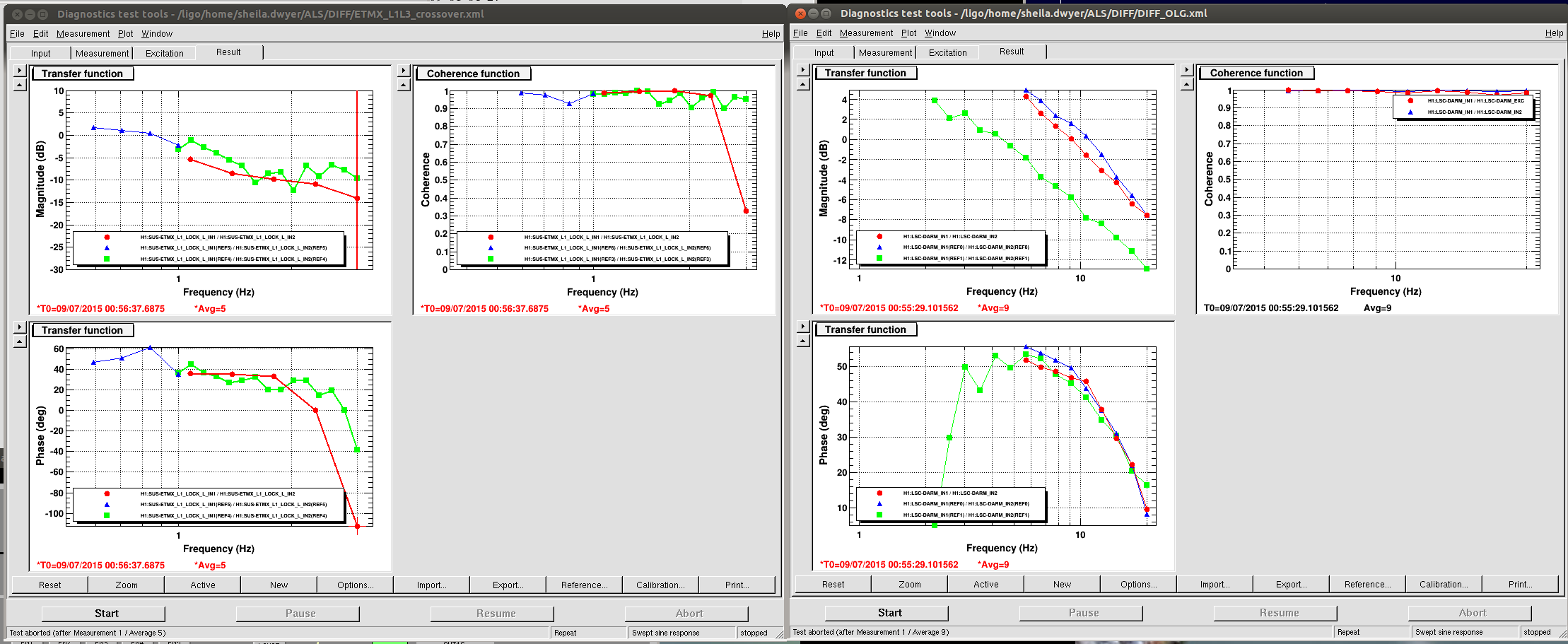
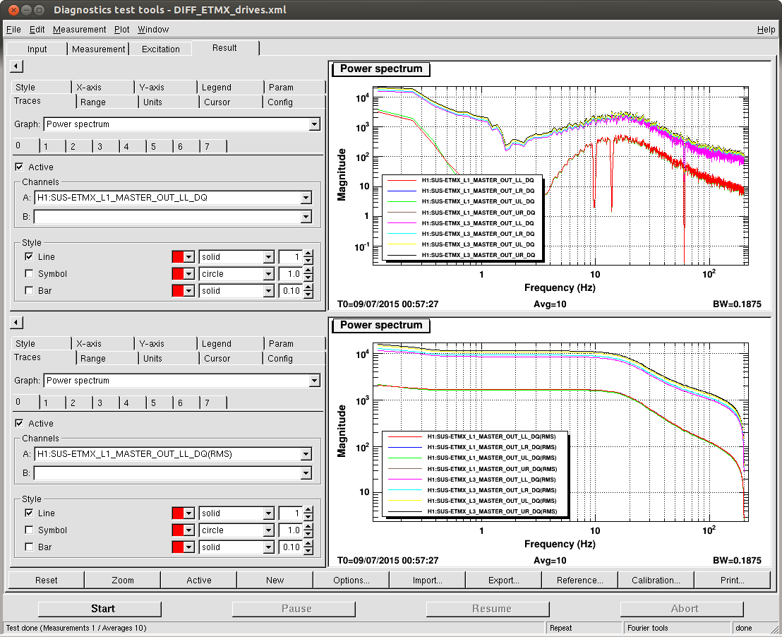
We noticed that in full lock (before power up) we again have questionable WFS. Indeed it seems to again be SRCL1 YAW that runs away - slowly at low power, but rapidly at high power. This is all a deja-vu, see elogs 18442, 18923, 18931.
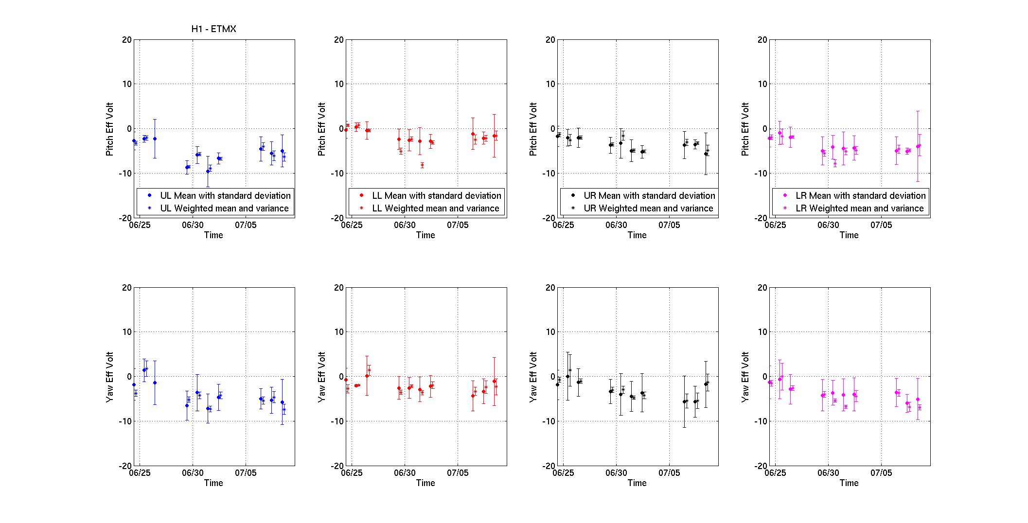
More investigation suggested that it is actually the QPD loops that pull us into a regime where the other loops are not stable. So for now we changed the QPD loop offsets at low power to just keep us at the same location:
New values: H1:ASC-X_TR_A_PIT_OFFSET H1:ASC-X_TR_B_PIT_OFFSET H1:ASC-X_TR_A_YAW_OFFSET H1:ASC-X_TR_B_YAW_OFFSET
-0.084
-0.212
-0.023
0.006
Old values: H1:ASC-X_TR_A_PIT_OFFSET H1:ASC-X_TR_B_PIT_OFFSET H1:ASC-X_TR_A_YAW_OFFSET H1:ASC-X_TR_B_YAW_OFFSET
-0.029
-0.158
-0.007
0.105
However we still lost it on POWER UP. More work needed here.
We also reverted the changes from earlier today (alog 19511): ETMX ISCINF gain back to 1, and the L1 gain back to 0.28. This now gave us a lower peak-peak ESD drive and - unlike earlier today - ALS DIFF engaged just fine... (no idea why it acted up earlier...)
Comments related to this report
old offsets
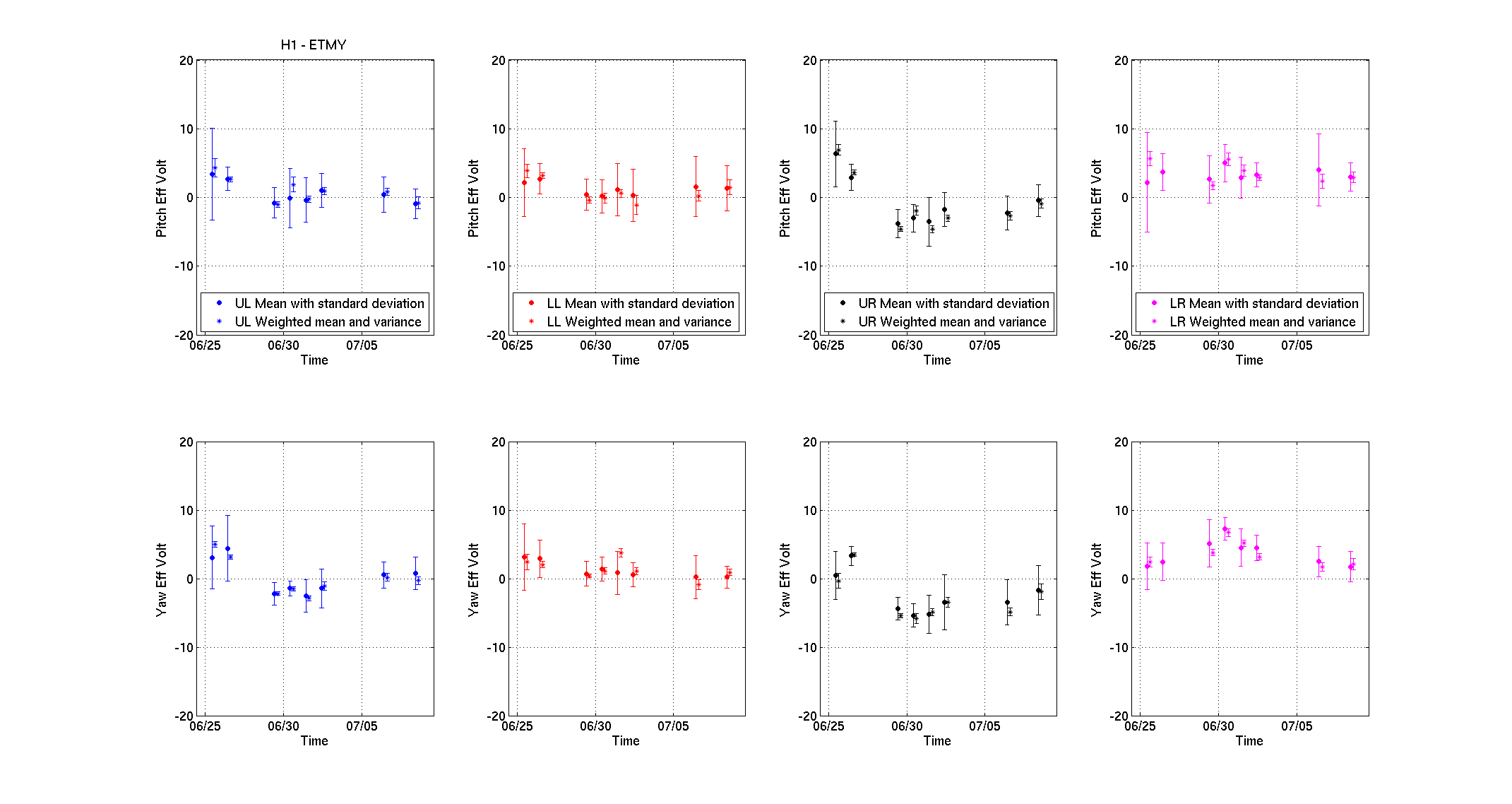
H1:ASC-Y_TR_A_PIT_OFFSET = 0.101
H1:ASC-Y_TR_A_YAW_OFFSET = -0.127
H1:ASC-Y_TR_B_PIT_OFFSET = -0.056
H1:ASC-Y_TR_B_YAW_OFFSET = 0.055
H1:ASC-X_TR_A_PIT_OFFSET = -0.0841
H1:ASC-X_TR_A_YAW_OFFSET = -0.023
H1:ASC-X_TR_B_PIT_OFFSET = -0.212
H1:ASC-X_TR_B_YAW_OFFSET = 0.006
new (temporary) offsets
H1:ASC-Y_TR_A_PIT_OFFSET = -0.192
H1:ASC-Y_TR_A_YAW_OFFSET = -0.365
H1:ASC-Y_TR_B_PIT_OFFSET = -0.32
H1:ASC-Y_TR_B_YAW_OFFSET = -0.237
H1:ASC-X_TR_A_PIT_OFFSET = -0.084
H1:ASC-X_TR_A_YAW_OFFSET = -0.023
H1:ASC-X_TR_B_PIT_OFFSET = -0.212
H1:ASC-X_TR_B_YAW_OFFSET = 0.006OLD
H1:ASC-Y_TR_A_PIT_OFFSET = 0.101
H1:ASC-Y_TR_A_YAW_OFFSET = -0.127
H1:ASC-Y_TR_B_PIT_OFFSET = -0.056
H1:ASC-Y_TR_B_YAW_OFFSET = 0.055
H1:ASC-X_TR_A_PIT_OFFSET = -0.0841
H1:ASC-X_TR_A_YAW_OFFSET = -0.023
H1:ASC-X_TR_B_PIT_OFFSET = -0.212
H1:ASC-X_TR_B_YAW_OFFSET = 0.006
H1:ASC-Y_TR_A_PIT_OFFSET = -0.192
H1:ASC-Y_TR_A_YAW_OFFSET = -0.365
H1:ASC-Y_TR_B_PIT_OFFSET = -0.32
H1:ASC-Y_TR_B_YAW_OFFSET = -0.237
H1:ASC-X_TR_A_PIT_OFFSET = -0.084
H1:ASC-X_TR_A_YAW_OFFSET = -0.023
H1:ASC-X_TR_B_PIT_OFFSET = -0.212
H1:ASC-X_TR_B_YAW_OFFSET = 0.006