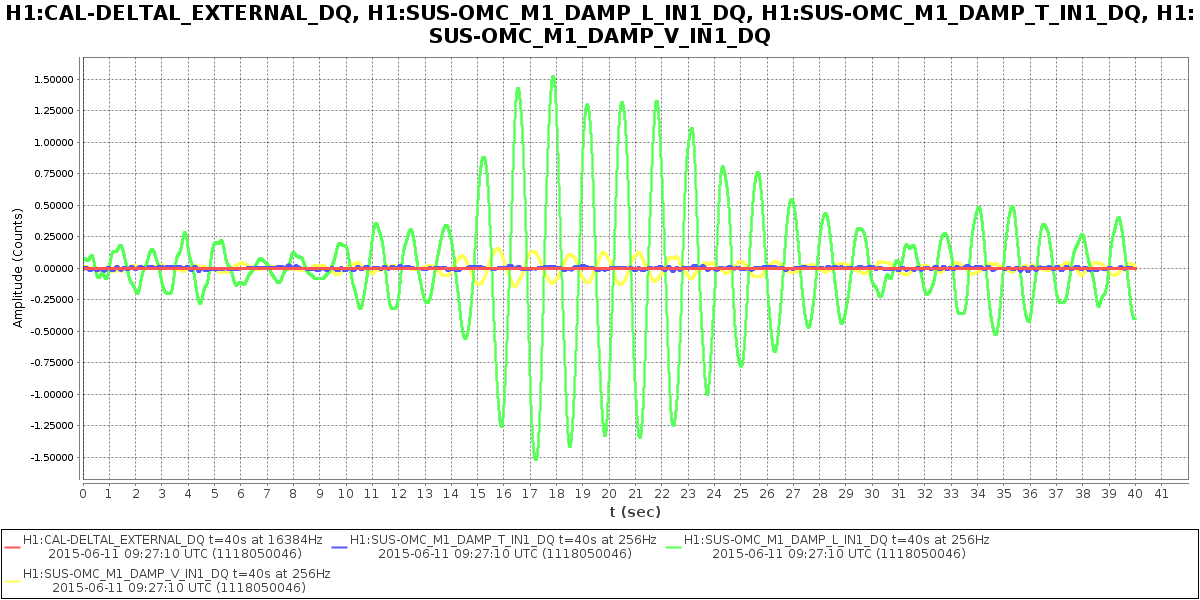
During ER7 there was some anecdotal evidence that the DARM gain was changing by a few percent between the handoff to DC readout and our high-power, low-noise state. One place this could happen is in the power-up step, where we changed the DARM offset to maintain a roughly constant light level on the OMC DCPDs. As the DARM offset changes the gain in the DCPD_Sum --> DARM path is scaled following a quadratic curve, but we know our approximation for the response doesn't include small static offsets, and maybe this has an effect on our gain scaling. In this post I try to quantify this error - turns out it should be on the order of a few percent.
DARM Gain Scaling in OMC-READOUT Path
Stefan and I didn't explain this very well after we commissioned the OMC-READOUT path, so I wanted to document how the variables in this path are set by the OMC Guardian. The carrier power at the AS port is assumed to follow a quadratic dependence on the DARM offset (see T0900023 for more math):
P_AS = (P0 / Pref) * (x / xf)**2 [Eq 1]
...where P0 is the input power, Pref is a power normalization factor, x is the current DARM offset*, and xf is an arbitrary constant we call the "fringe offset".
Step 1. When the OMC is locked on the carrier, Pref is set such that when the DARM offset is equal to the "fringe offset", x = xf, the output of the power normalization step in the OMC-READOUT calculation will be equal to P0:
Pref = (P0 / P_AS) * (x / xf)**2 [Eq 2]
Step 2. Small variations in DARM (dx) will generate small variations in the carrier power (dP) on the DCPDs, like so:
dP = (P0/ Pref) * (2*x / xf**2) * dx [Eq 3]
The OMC-READOUT path calculates dx and sends the following to the LSC input matrix:
G * dx(x,dP) --> DARM_IN1 [Eq 4]
..where dx is an explicit function of dP and the DARM offset, x. The overall gain factor G converts dx into counts at the DARM error point. G is calculated by taking the transfer function between dx and DARM_IN1. It's set before the handoff to DC readout, and not changed. After this point, the reponse of the light on the DCPDs to small length fluctuations (the slope, dP/dx) is assumed to be a linear function of the DARM offset, following Eq 3.
Static DARM Offset
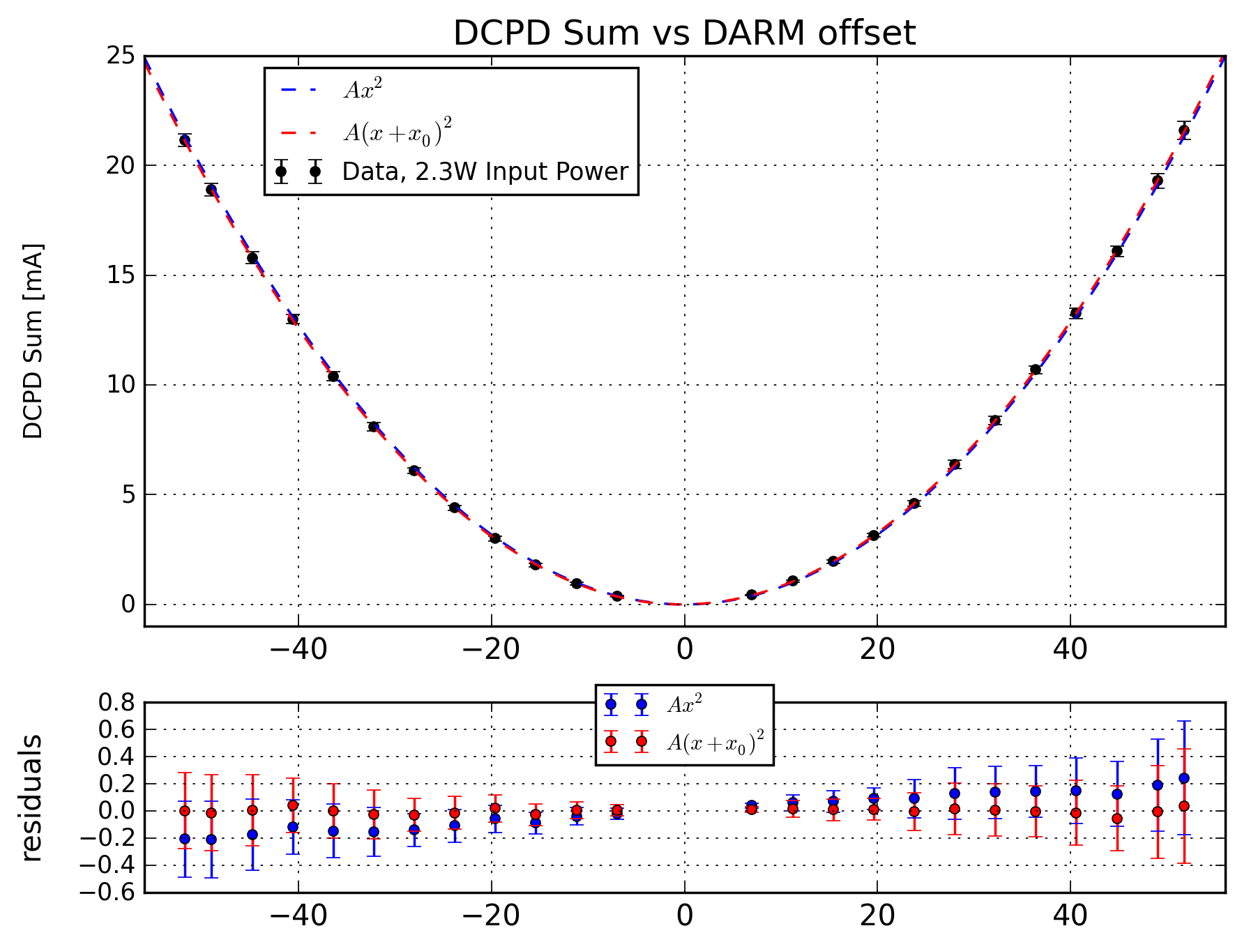
When Stefan and I set up the OMC-READOUT path, Keita pointed out that a static DARM offset was making our lives more complicated. Before ER7 I swept the DARM offset and measured the photocurrent on the DCPDs - the quadratic dependence has a clear offset from zero, see Figure 1. The residuals for the simple quadratic fit (blue) have a linear dependence on the offset, while the residuals for the fit that includes a static offset (red) are well-centered around zero. The best-fit value for x0 is -0.25 picometers, +/- 0.01 pm. We're not sure where this comes from, whether it's changing, etc (on May 15 Stefan calculated 0.6pm).
Effect of DARM Offset on DARM Gain
If there's a static offset, x0, our model of the carrier power as a simple quadratic is incorrect, and Eq 1 needs to be rewritten as:
P_AS = (P0 / Pref) * (x + x0)**2 / xf**2 [Eq 5]
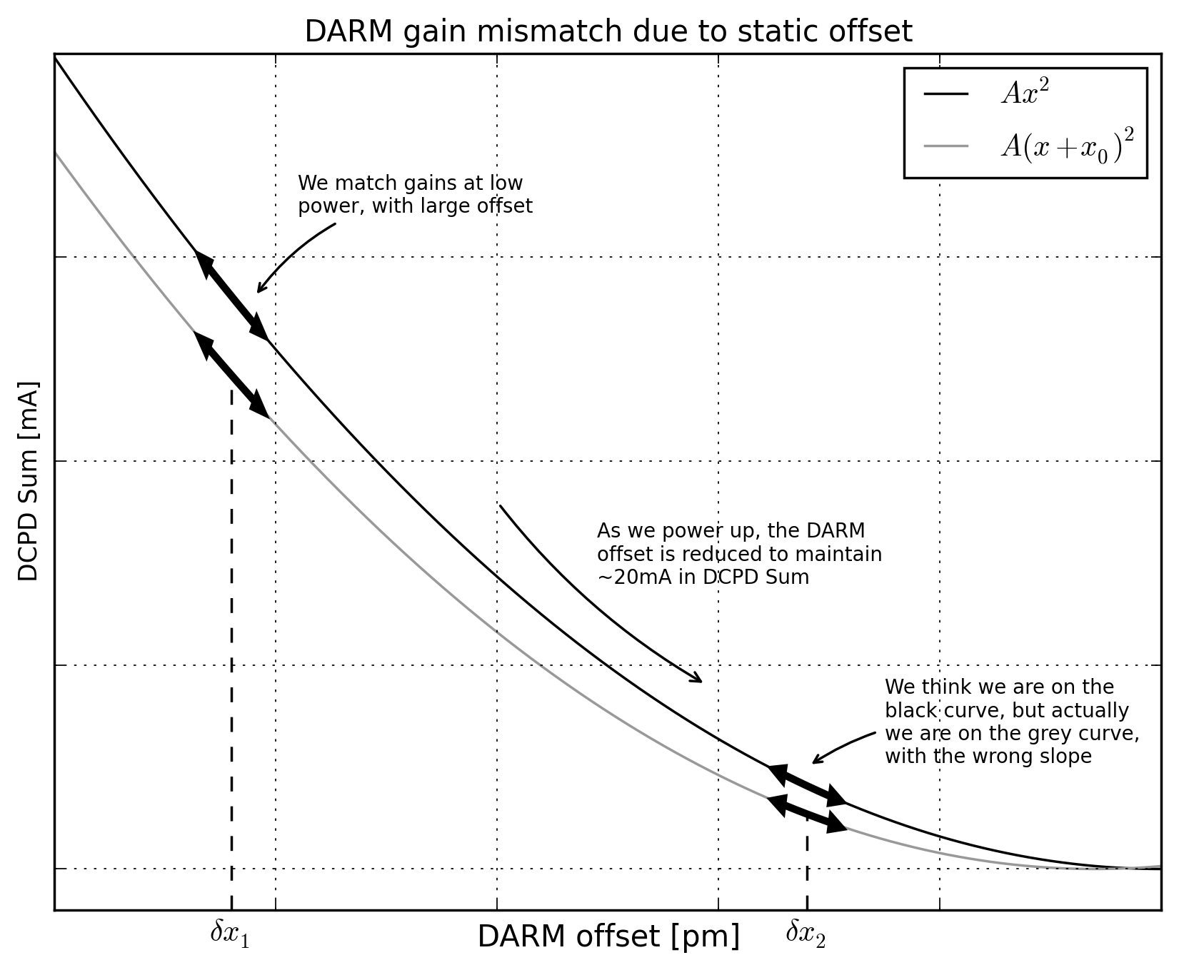
During the power-up step, we change the DARM offset to maintain ~20mA of photocurrent in DCPD_SUM, and we adjust the slope of dx(x,dP) accordingly, see Figure 2. If we're using Eq 1 instead of Eq 5, this gain-scaling is incorrect, and our DARM gain will change. For a negative static offset like we observe, the gain will be lower than it should be.
But, since the offset is very small, this effect is only 1-2%. Without going into exhaustive detail, the ratio of the slopes for a simple quadratic, Ax^2, and a quadratic that is offset from zero, A(x+x0)^2, is close enough to 1 for small values of x0 that I don't think we need to worry about it, see Figure 3. The error in the gain as we move from a DARM offset of ~42pm at 2.3W input power to ~16pm at 24W is 1% for x0=-0.25pm. For x0=-0.75pm the effect is 3%.
Summary: We have a small static DARM offset, this means our approximation of the DARM gain as a function of DARM offset is a little wrong. The effect should be small. Eventually we will account for the DARM optical gain in the calibration (the 'gamma' parameter) and small changes in the DARM loop gain will be absorbed into the calculation of CAL-DELTAL_EXTERNAL.
Edit: On further reflection, this isn't the case. We have a small static offset while locked on RF DARM, but after the handoff to DC readout this offset is absorbed into the power normalization (the Pref variable, Eq 2). Once DARM is locked on DC, a zero offset will result in zero carrier light at the dark port, by definition. A small offset might change the gain scaling at the handoff such that we observe a few percent difference from what we expect, but the mechanism is not what I describe here. Will have to think about it more.
* In the OMC-READOUT path, the DARM offset is referred to as OMC-READOUT_X0_OFFSET. Here I call it 'x', and refer to the static offset as 'x0'. Sorry.