Description
See the attched figure.
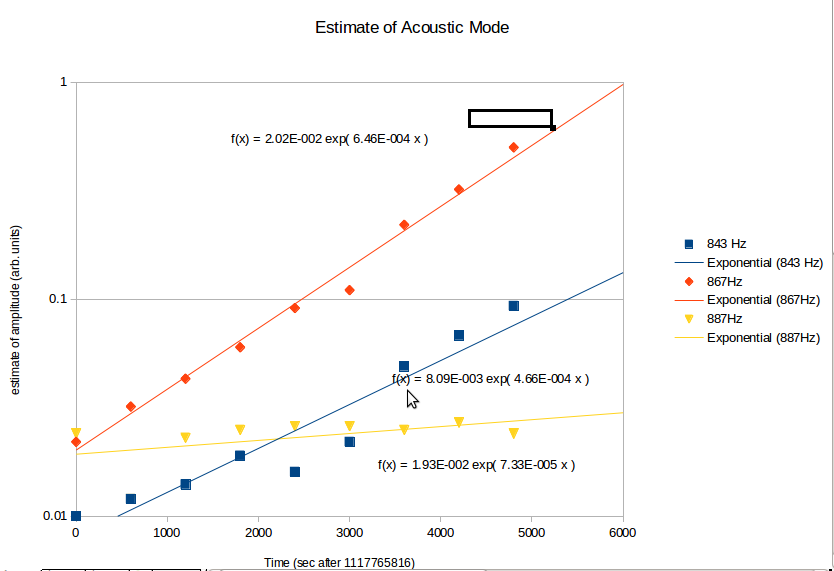
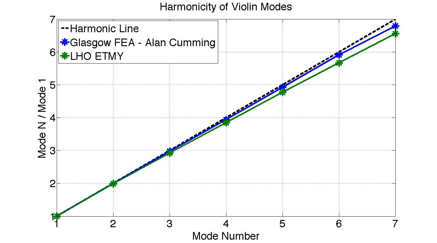
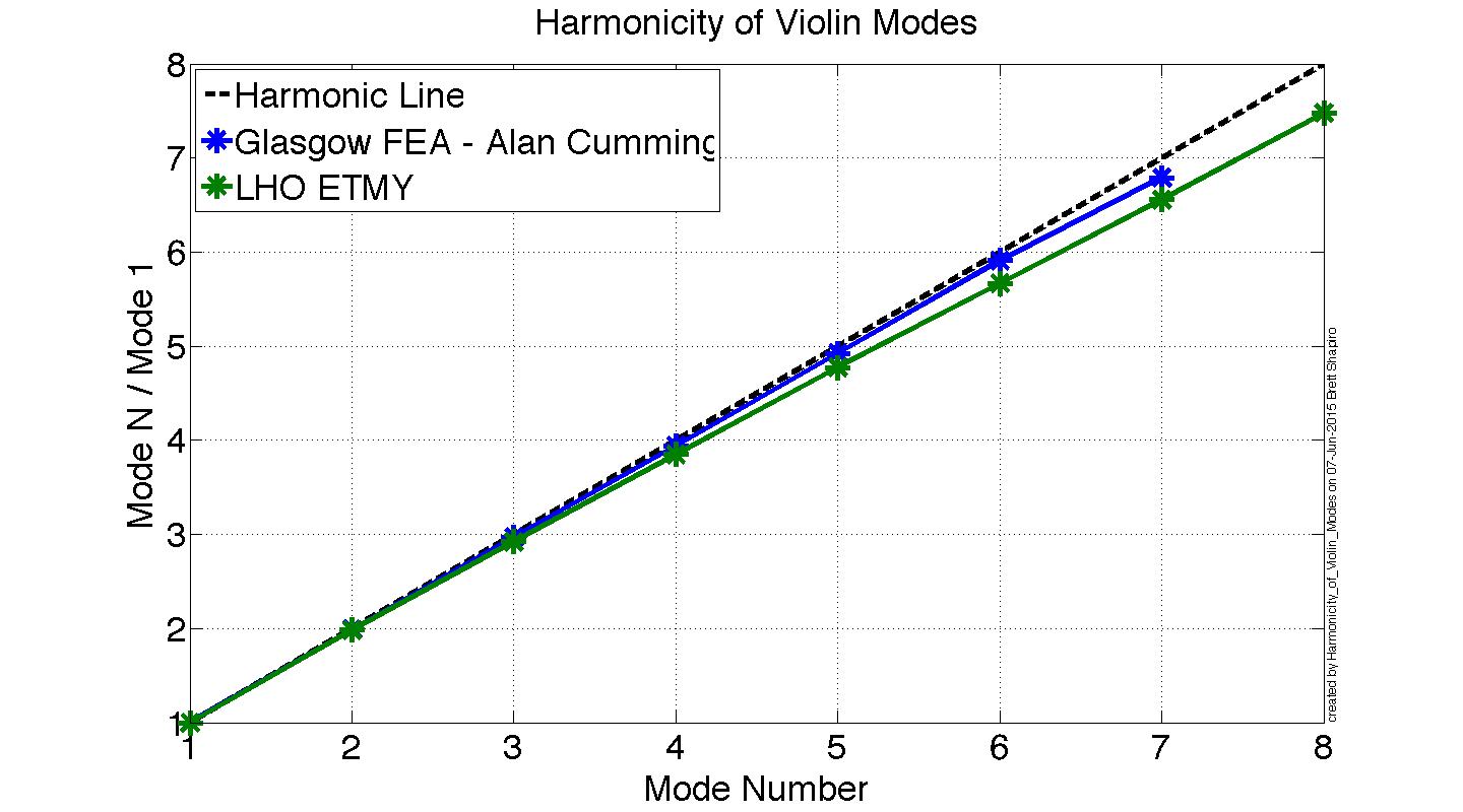
The violin modes are not harmonics of each other, as we know. But they aren't harmonic in a rather interesting way, because the frequencies are less than harmonic. We might expect that the mode frequencies be greater than the harmonic values because of the bending stiffness of the fiber. Only a completely floppy string is harmonic. The fiber's modulus of elasticity will tend to become more important at higher mode numbers, increasing the frequencies.
However, we observe that the modes are lower in frequency than the harmonic values. The attached plot shows how close (or far) the modes are to harmonic. The y axis is the ratio of a mode's frequency to the first mode. The x axis is the mode number. An ideal harmonic system has a slope of 1. This is represented by the dashed black line. The blue line is from an FEA done by Alan Cumming at Glasgow University. This FEA takes into account the non-uniform shape of the fiber. The green line is from measurements of LHO ETMY.
Analysis
The FEA does indeed predict that the fiber should be less than harmonic. This could be because the 400 micron diameter fiber has 20 mm long 800 micron sections at the ends. Perhaps the effective bending point moves along the 800 micron section.
However, the measurements are even less harmonic than the FEA. It is not clear why this is. One possibility, though this sounds a bit crazy (but I can't think of anything else), is that the fiber is pitching the PUM and test mass as it oscillates. If the masses pitch, it makes the fiber behave as if it were longer, moving the frequencies down. Higher modes might exert more pitch torque becasue the fiber has more slope at its ends.
Running some numbers on the fiber length, The nominal value of 587 mm gives a fundamental frequency of 507 Hz, very close to ETMY (508 Hz) and within the spread of the other suspensions. But for ETMY mode 4, I have to increase the length by 20 mm. For ETMY mode 7 this is nearly 40 mm, which puts the bending point somewhere in the ears I think. For reference, the centers of mass are 602 mm apart.
Data
The mode frequencies in Hz used in the attached plot are
FEA from Alan Cumming:
511, 1017, 1519, 2013, 2515, 3020, 3470
LHO ETMY:
508.3, 1009.1, 1484.5, 1956.7, 2425.8, 2880.6, 3333.2
The LHO ETMY data came from the following alogs
17610 - mode 1, averaged over the 4 given frequencies
17365 - modes 2 and 3. Mode 2 is averaged over the 4 given values. Mode 3 only has 1 value.
18764 - mode 4. This list doesn't specify which modes are which suspension. I chose to average the 4 highest values assuming they are ETMY because for all other modes ETMY is the highest.
18614 - modes 5, 6, and 7. I averaged the 2 given values for each of these modes.
1009
1485
1957
2426
2881
3333
508
1009
1485
1957
2426
2881
3333

I've noticed that as well. I would suggest filing a bug against the "alog" product in the CDS bugzilla:
https://bugzilla.ligo-wa.caltech.edu/bugzilla3/enter_bug.cgi?product=alog
You should also make the "Section" of this log entry be "Logbook Admin".