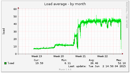
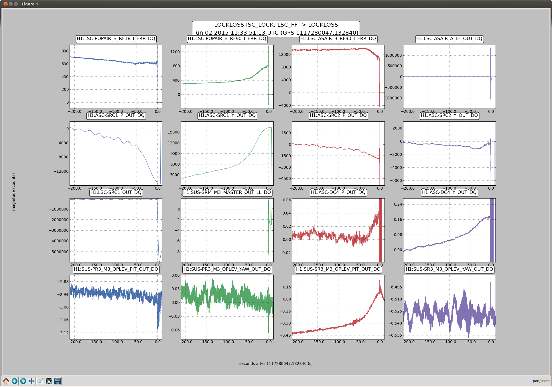
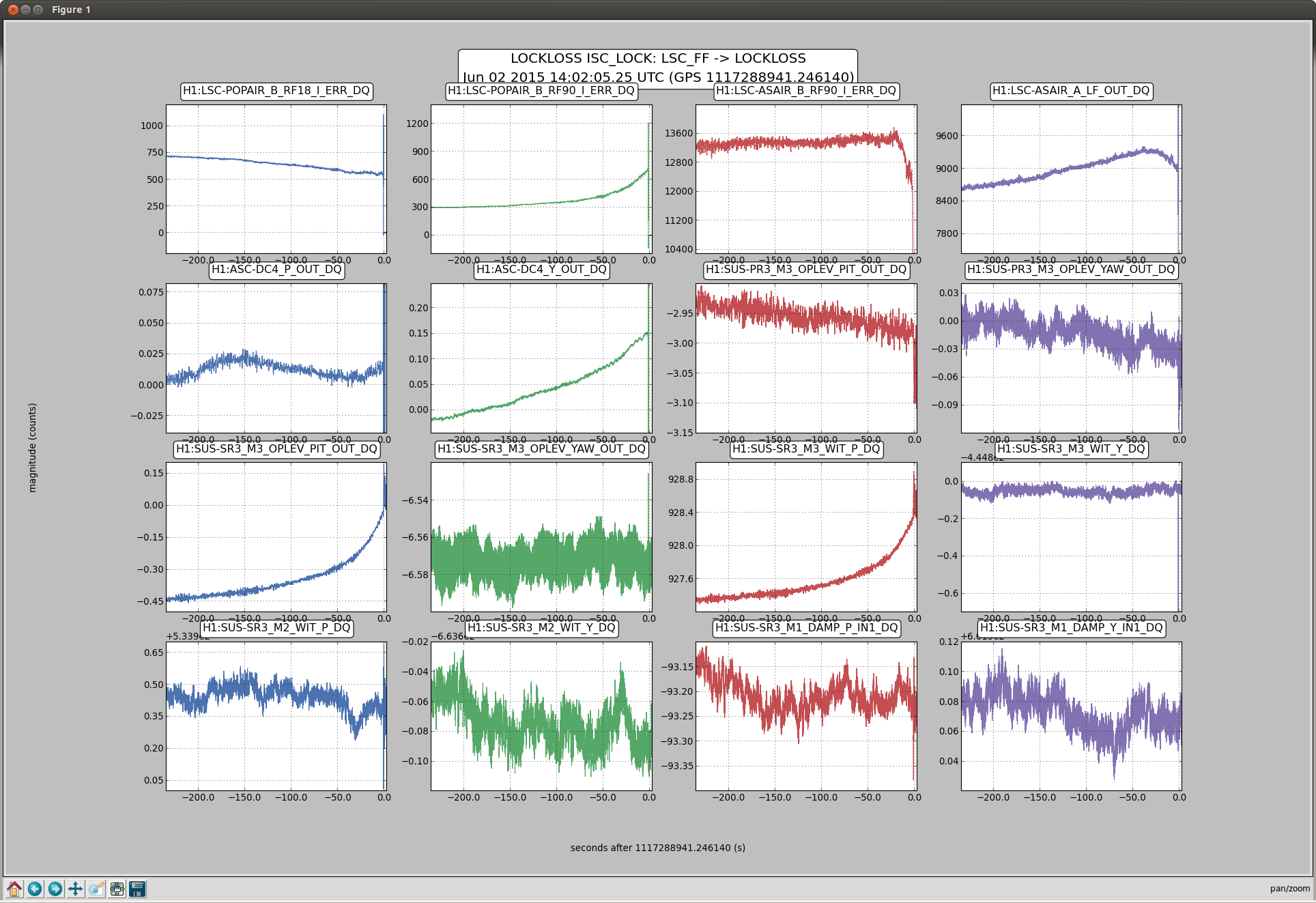
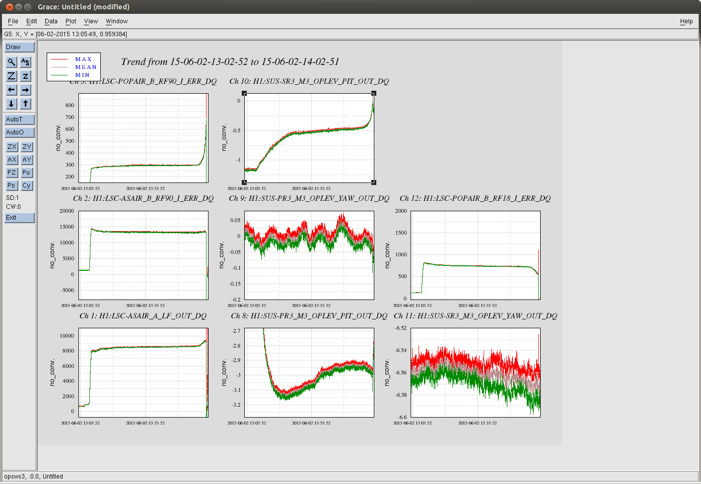
Daniel and I looked at three of the locklosses from Travis's shift last night, from 14:40, 14:02 and 11:33 UTC. The earlier two both seem to be related to an alignment drift over 2-3 minutes before the lockloss, which shows up clearly in SR3 PIT. (there is currently not feedback to SR3 PIT) According to the witness sensors, this drift is only seen on M3. No optics saturated until after the lockloss. The DC4 centering loop, as well as both of the SRC alignment loops respond to the drift.
Its unclear what causes the drift to accelerate in the minutes before the lockloss. There is also a drfit of SR3 when we power up, as we noted yesterday, but this happens on a slower timescale than the dirfts that preceed a lockloss (3rd screenshot). Also, there is a longer, slow drift that happens whenever we are locked.
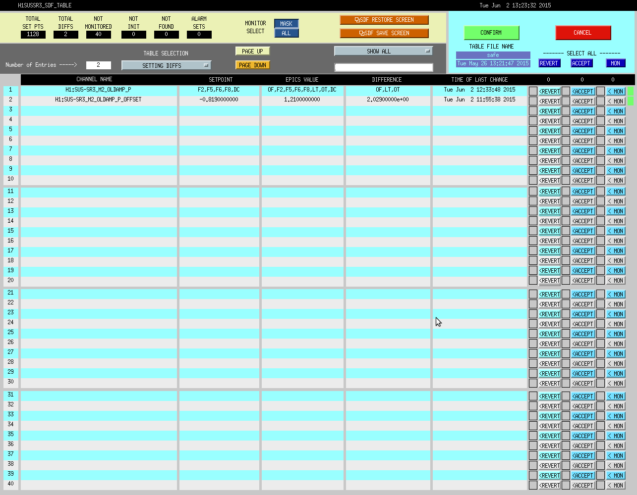
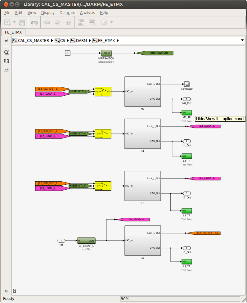
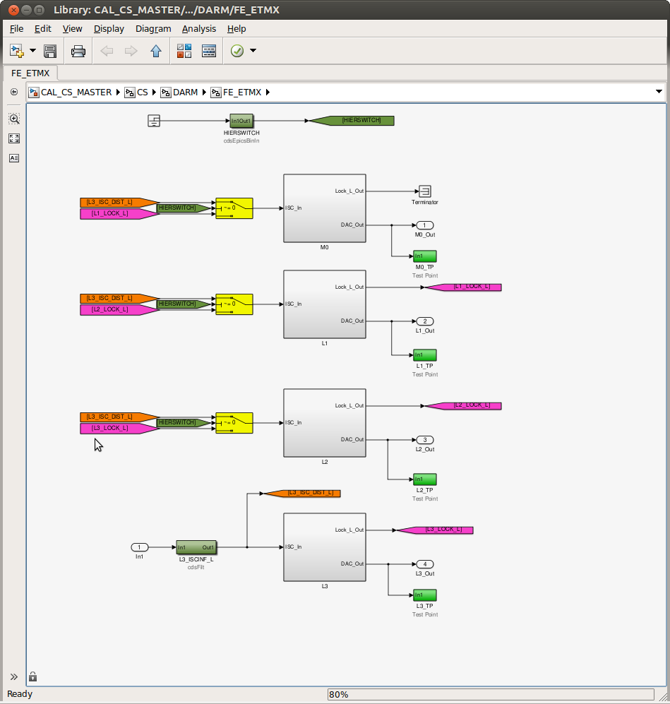
With Patrick and Cheryl I have engaged a DC coupled optical lever for SR3 PIT, we will see if this helps. The last screen shot attached shows the MEDM screen used to turn this on or off.
If the operators need to disable this (due to an earthquake, a trip, or if the optic becomes misalinged for any other reason) you can get to this screen from SR3, M2 OLDAMP.
Turning off:
turn off FM1 (labeled DC), then the input
Turning it back on:
Once the optic has settled and the beam is back on the oplev QPD, turn on the damping loop (with FM1 still off). Average INMON (in a command line tdsavg 10 H1:SUS-SR3_M2_OLDAMP_P_INMON), type -1 times the average into the offset, make sure the offset is engaged, and finally turn on FM1 to make the loop DC coupled.
Since this is just a trial, Jeff is not including these changes in his current SDF cleanup campaign.


We've had three locklosses at 23 Watts in the last 4 hours. The first one of these did coincide with a gust of wind (plot attached), although it might not have been the cause. We've been able to stayed locked with gustier wind in the past at 10 Watts.
In all three of these locklosses there were fluctuations in the POP90 power on 10s of seconds timescales.