J. Kissel, K, Izumi
I had started the weekend hoping to improve the DARM calibration in the following ways:
(1) Including the compensation for the analog and digital anti-aliasing (AA) and anti-imaging (AI) filters.
(2) Decreasing the DARM coupled cavity pole by 25% to 290 [Hz].
(3) Establishing an uncertainty estimate of the optical gain (the DC scale factor component of the sensing function).
(4) Reducing the delay time in the actuation from four 16 [kHz] clock cycles to one 16 [kHz] clock cycles.
After study, and Sunday's improvement to the power recylcing gain, we've decided not to make *any changes to the calibration, yet.
However, for the record, I put down what I've studied here, so we can begin to understand our uncertainty budget.
%% Details
-----------
(1) Including the compensation for the analog and digital anti-aliasing (AA) and anti-imaging (AI) filters
LLO has pioneered a method to compensate for the high frequency effects of the analog and digital (or IOP) AA and AI filters, by including the *product* of all four filters in the actuation chain of the front-end CAL-CS model (see the last few pages of G1500221 and LLO aLOG 16421).
Further, Joe has analyzed a collection of 281 real, analog AA/AI filters that were tested during CDS acceptance testing to refine the exact frequency response of these filters (see first attachment, aLIGO_AAAI_FilterResponse_T1500165.pdf). In summary, the 3rd order Butterworth's corner frequency is statistically significantly lower; measured to be 8.941 (+0.654 /-0.389 or +7%/-3%) [kHz] instead of the ~10 [kHz] Butterworth model that we have been using (which was inherited from a .mat file the 40m). Though this does not appreciably affect the magnitude error at high-frequency, it does as much as 3 [deg] of phase by 2 [kHz], which can throws off our estimate of the residual unknown time delay by 5 [us] when we try to account for it in our fitting of the open loop gain transfer function.
However, after exploring what LLO has implemented, we've discovered a flaw in the implementation of this compensation. In going from the continuous zpk model of the filters to discrete, because we're trying to model these filters which have all of their response near, at, or above the Nyquist frequency, there is significant difference of modeled filter's response between the continuous and discrete models (see second attachment 2015-04-18_AAAI_FilterStudy.pdf).
As such, we will *not* begin to compensate for the AA and AI filtering until we arrive at a better method for compensating these filters.
(2) Decreasing the DARM coupled cavity pole by 25% to 290 [Hz].
Over the past few weeks, we've established the DARM coupled cavity pole is now at 290 [Hz] instead of the predicted L1 value of 389 [Hz] (see LHo aLOG 17863). We've added one more DARM open loop gain transfer function to the list we're now comparing after the HAM6 vent,
Apr 13 2015 04:15:43 UTC % Post HAM6 Vent & UIM/TST Crossover; 10 [W] input power
Apr 13 2015 06:49:40 UTC % No loop parameter changes, but input power 15 [W]
Apr 15 2015 07:53:56 UTC % Input Power 15 [W] no change in control system from previous measurement
with these three measurements, I made a statistical comparison of the model / measurement residual while using 290 [Hz] for the modeled coupled cavity pole frequency, and reducing the unknown time delay from 40 [us] to 30 [us] because I've used Joe's measured mean for the analog AA / AI in the model (see third attachment 2015-04-18_290HzCCP_H1DARMOLGTF.pdf ). As one can see on the 3rd and 4th page, assuming each of the residuals frequency points is a measurement of the the true OLGTF value with a Gaussian distribution, the uncertainty in the frequency dependence of the OLGTF model is now a 1-sigma, 68% confidence interval of +/- 1.5% in magnitude and 1 [deg] between 15 and 700 [Hz] (IF we change the CCP frequency to 290 [Hz], compensate for the AA and AI filters, and include 30 [us] of unknown delay). Note that this assumption of Gaussianity appears to be roughly true for the magnitude, but not at all in phase (I'm still thinking on this). Also note the each one of these frequency points has passed a 0.99 coherence threshold on a 10 [avg] measurement (and most have coherence above 0.995), so the individual uncertainty for each point is sqrt((1-coh)/(2*nAvgs*coh)) = 1 to 2%.
Recall the frequency dependence of the model is determined by the following components included in the model:
- The 1/f^2 dependence of the [m/N] suspension transfer function (as modeled by the QUAD state space model)
- The 2000 [Hz] ESD driver pole
- The analog and digital anti-imaging filters
- The 130 [us] of actuation delay from 1 16 [kHz] cycle of SUS Computation, 3 65 [kHz] cycles of IOP Error Checking, 1 65 [kHz] cycle of IOP Computation, and 1/2 65 [kHz] cycle for Zero-order Hold Delay
- The DARM filters
- The single-pole response (at 290 [Hz]) of the optical plant
- The analog and digital anti-aliasing filters
- The 76 [us] of sensing delay from 1 65 [kHz] cycle of IOP Computation, 1 16 [kHz] cycle of OMC Computation
- The 30 [us] of unknown time delay
As a cross-check, I recalculated the comparison with the CCP frequency that's currently used in the model, 389 [Hz], and found that at around the high-frequency PCal lines, roughly ~535 [Hz] the model / measurement discrepancy is 25-30%. This is consistent with what the PCAL calibration reports at these frequencies, a DARM / PCAL (which is equivalent to model / measurement) discrepancy of 25-30% -- see LHO aLOG 17582. At the time, the PCAL team reports their internal uncertainty to be in the few-percent range.
This had convinced me on Saturday that I had enough information to "officially" change the DARM CCP frequency in the CAL-CS front end, but Gabriele and Evan have since changed the alignment scheme for the corner station to improve the power recycling cavity gain by improving the ITM DC alignment LHO aLOG 17946. This will have an effect on the signal recycling cavity and therefore the DARM CCP frequency, so we'll wait until we get a few more OLGTFs in this new configuration before changing anything.
(3) Establishing an uncertainty estimate of the optical gain (the DC scale factor component of the sensing function).
After refining the precision of the frequency dependence in magnitude, this allows to quantify the precision to which we can estimate the overall DC scale factor that one needs to scale the model to the measured OLGTF; a factor that we traditionally have attributed only to the change in optical gain between lock stretches. For this study, I've used *all* six DARM OLGTF TFs, see 2015-04-18_AllMeas_FittedCCP_H1DARMOLGTF.pdf. Note that this increases the uncertainty of the frequency dependence to a less Gaussian 2.5%, but as you'll see this is still plenty precise.
Recall that before transition to the OMC DCPDs, regardless of input power to the IFO, the OMC_READOUT sensor gain is changed to match the RF readout sensor gains which are already power normalized. That should mean that input power should have no affect on the measured optical gain, and this is a safe comparison.
With 6 measurements, the mean scale factor for the OLG TFs is 1.05e6 +/- 26% [ct / ct]. This is consistent by the variation the DARM digital gain by 34% that was used for these 6 measurements. The current optical gain used for the sensing function the CAL-CS front end model is 1.1e6 [ct/m]. This 4% difference from the mean of the these 6 measurements is well within the 26% uncertainty, so we've concluded to *not* change anything there.
All this being said, we have used the *same* actuation strength for all of these comparisons, but there is no guarantee that the actuation strength is not changing along with the optical gain.
- ETMY is controlled using the Test Mass (L3) and UIM (L1) stages
- The cross-over for these two stages in the two groups of measurements is ~1.2 [Hz] and 2.5 [Hz] (see 17713), and by 10 [Hz], the contribution of the UIM is roughly -25 [dB] and -15 [dB]. Therefore the ESD is the dominate actuator in the frequency region which we're we trying to
- Static charge affects the actuation strength of the ESD by changing the effective bias voltage of the drive, as well as changing the amount of drive that's in the longitudinal direction (because the charge can migrate to different regions of the reaction mass / test mass gap), see e.g. G1500264, LLO aLOG 16611, or LLO aLOG 14853.
- If there is substantial residual charge on the ESD, the charge varies on the the ESD when Ion Pumps are valved into the chamber.
- It has been shown many times over that the charge varies on the few hour time scale when there is significant residual charge on the test mass and the ion pumps are valved in (see e.g., G1401033 or as recently as LLO aLOG 17772).
Thus, it is reasonable to suspect that the actuation strength is changing between these measurements. LHO has made no-where-near enough measurements (only a one-time comparison between ETMX and ETMY, see LHO aLOG 17528) to quantify how much this is changing, but here is what is possible:
- We have a physical model of the actuation strength (or at least more accurate equation for how the bias voltage determines the actuation strength, see above citations). I think we can take what we've seen for the variance (as high as +/- 400 [V] !!) and propagate that through to see how much of an affect it has on the strength
- PCAL lines at low-frequency (~30 [Hz]), compared against the DARM calibration lines should show how the optical gain is varying with time, it's just that no one has completed this study as of yet.
- Calculation of the gamma coefficient from the DARM lines should also reveal how the open loop gain transfer function is changing with time. In the past, we've assumed that changes in gamma are fluctuations in the optical gain because we've had actuators with non-fluctuating strength.
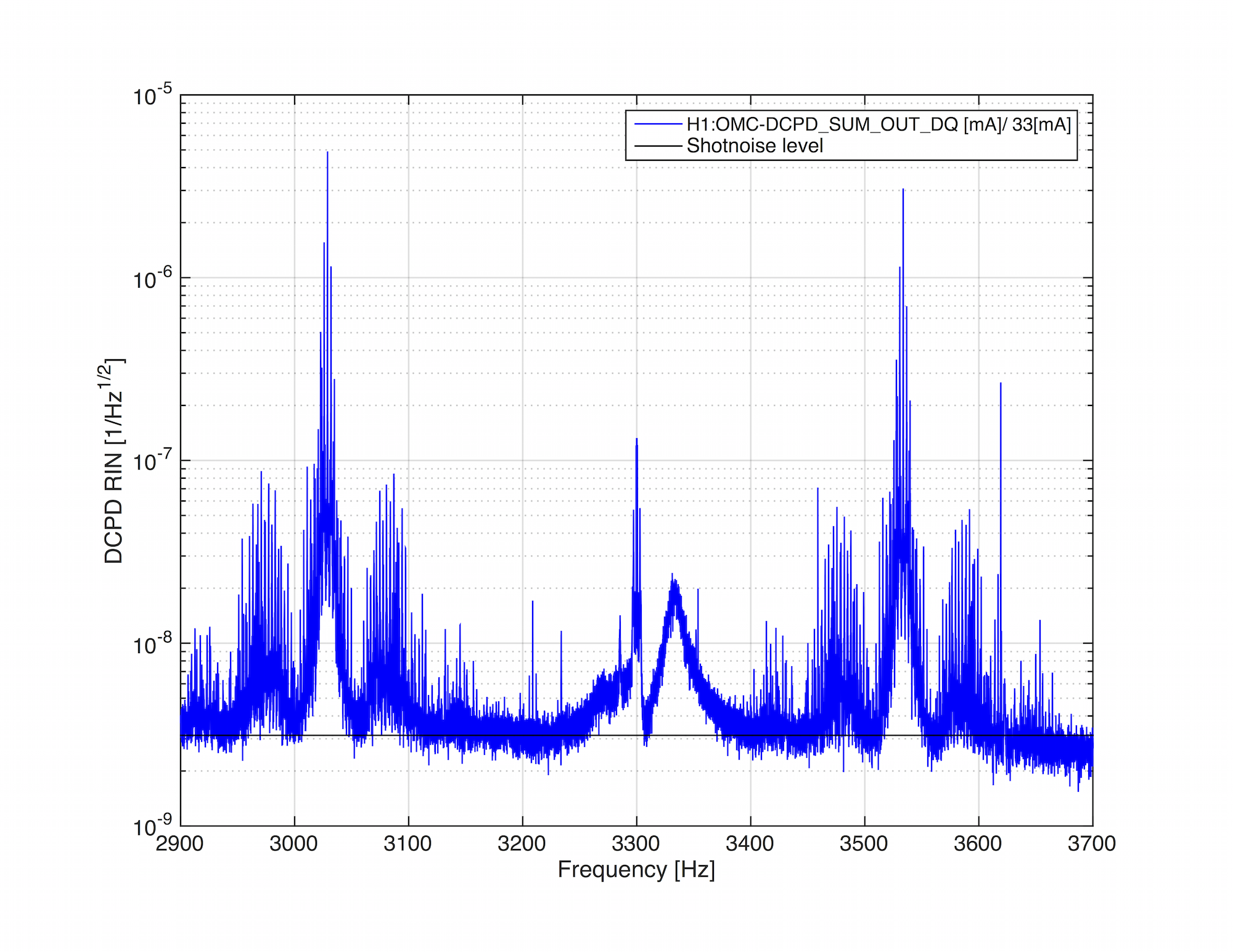
Thus, for now, we'll incorrectly assign all of the uncertainty in the scale factor to optical gain, and call is 26%. Perhaps it will be much better to trust PCAL at this point and time, since it's precision is so much greater than this "scale the OLGTF model" method, but I would need a third measurement technique to confirm the accuracy. I think a power budget propagated to a shot noise estimate compared against the measured ASD (like in LHO aLOG 17082) is the easiest thing to do, since it can be done offline. Or we should resurrect the campaign to use the IMC VCO as a frequency reference, but this has the disadvantage of being an "offline, odd configuration" measurement, just like the free-swinging Michelson.
(4)Reducing the delay time in the actuation from four 16 [kHz] clock cycles to three 16 [kHz] clock cycles.
As mentioned above, the time delays that are included in this model are
- The 130 [us] of actuation delay from 1 16 [kHz] cycle of SUS Computation, 3 65 [kHz] cycles of IOP Error Checking, 1 65 [kHz] cycle of IOP Computation, and 1/2 65 [kHz] cycle for Zero-order Hold Delay
- The 76 [us] of sensing delay from 1 65 [kHz] cycle of IOP Computation, 1 16 [kHz] cycle of OMC Computation
- 30 [us] of unknown time delay (the equivalent of ~8-9 [deg] of phase at 700 [Hz])
for a total of 206 [us] of delay for which we've accounted, out of the total 236 [us] that's used to produce the above frequency-dependence comparison. So, there's a total of 3.4 or 3.9, 16 [kHz] cycles of known or known+unkuown time delay, respectively. Remember that the "L/c", light-travel time delay (13 [us]) is *less* than the one 16 [kHz] SUS clock cycle (61 [us]) delay that defines when the control signal arrives at the end station over RFM IPC, so we ignore it.
Since we only have the infrastructure add the delay in the actuation paths in CAL-CS, then we can only account for the *differential* delay between the two paths. If we assign the unknown delay to the actuation side of things, then the difference in delay between the two paths is (130+30)-76 = 84 [us] = 1.3 16 [kHz] clock cycles, leaving a residual overall delay of 76 [us]. If we assign it to the sensing function, we get 130-(76+39) = 24 [us] = 0.39 16 [kHz] clock cycles, leaving a residual of 130 [us]. Since we can't do less than 1 [kHz] clock cycle, we should chose to assign the unknown delay to the actuation function, apply one 16 [kHz] cycle delay to the actuation function, and suffer the 0.3 / 16384 = 18 [us] phase difference between the sensing and actuation path, and have to account for a 76 [us] delay in offline analysis.