Evan, Dan, Sheila. Kiwamu
This afternoon we moved the picomotors on both transmon IR QPD sleds, although we moved Y much further than X. This was to reduce the clipping and saturation Keita pointed out in 18077. After that we excited TMSY in both pitch and yaw, and found error signals for the ITMs that are insensitive to TMS again.
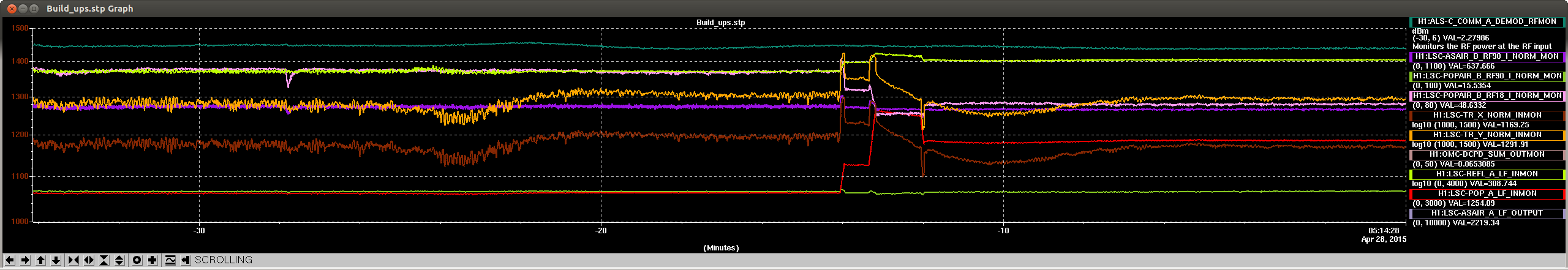
We have closed all the loops in full lock and things seem stable, we were able to increase the power at 12:00 UTC on the 28th and saw that the recycling gain stayed stable. We stopped at 6 Watts because the Y QPD is near saturation. We should probably do more picoing (most of the light is on one quadrant), and reduce the whitening gain.
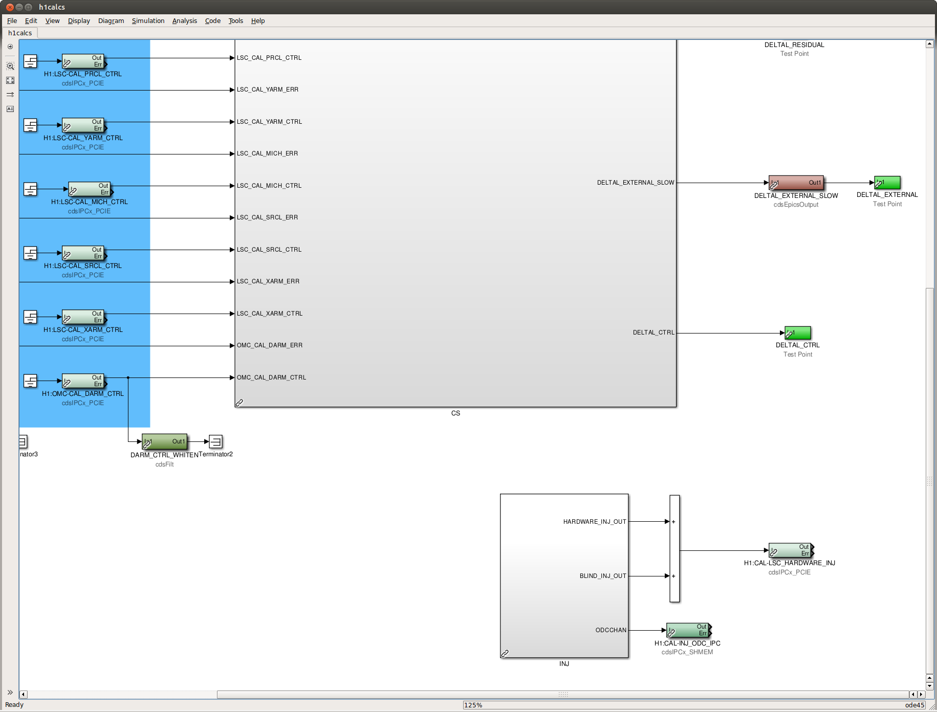
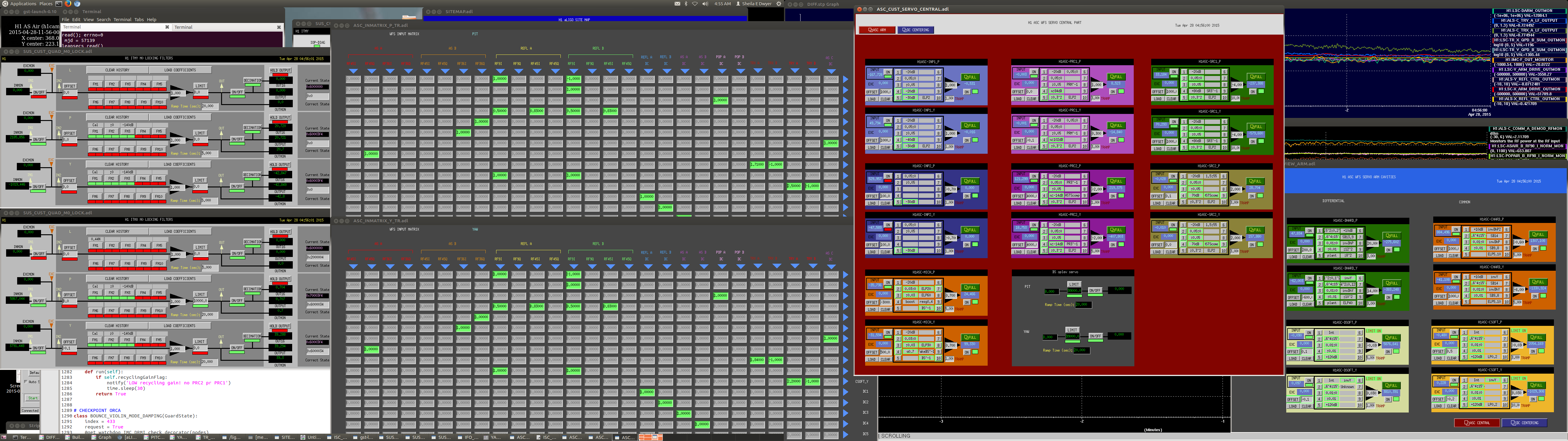
The attached screenshot shows the settings we have now, the DSOFT and CSOFT loops could have gain of 1, but we were cautious.
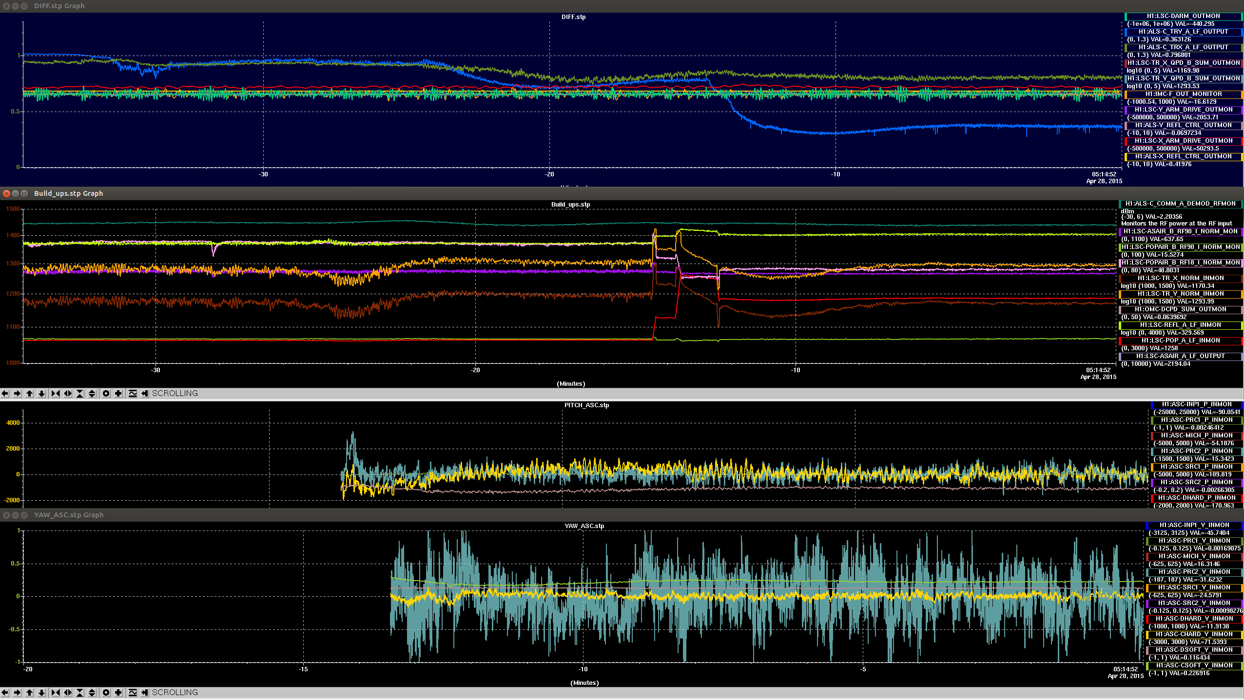
We had some difficulty turning on the ASC loops earlier tonight. One thing that we noticed was that we were able to close INP1 each time, even when we didn't close PRC2 or CHARD (or SRC). We also had trouble closing the CHARD PIT loop, although YAW was fine. Once we manualy adjusted the alignment to improve the recycling gain and closed the ITM loops, we closed CHARD PIT with no problems.
We have left the ASC engage commented out in the guardian, because it is not working right now. We also attempted earlier in the evening to take Keita's advice and manually aling the green PZT durring a full lock with good recycling gain. We had difficulty getting the build ups high while minimizing the WFS signals, we adjusted the QPD offsets to keep the build ups high but this resulted in a bad recycling gain. Probably a more thorough attempt is waranted.
ETMX ESD tripping
Since saturday, the ETMX ESD has been tripping almost every lockloss. We also need to toggle BO 4 to reset it, which is not required to reset ETMY.