Displaying reports 7001-7020 of 88198.Go to page Start 347 348 349 350 351 352 353 354 355 End
Reports until 00:49, Friday 28 March 2025
H1 General (Lockloss, SEI)
ryan.short@LIGO.ORG - posted 00:49, Friday 28 March 2025 - last comment - 07:05, Friday 28 March 2025(83606)
Lockloss @ 06:33 UTC from EQ and ISI Trips

H1 called for assistance at 07:13 UTC when ISIs tripped for every QUAD, BS, and HAM8 due to a M7.7 earthquake and M6.4 aftershock out of Myanmar. Lockloss happened earlier at 06:33 UTC because of the S-waves of this quake, I'm assuming. At the worst of the shaking, peakmon was at the highest I can recall seeing it at over 128,000 counts.

H1 will be down for a while. I'll check in after a bit and untrip platforms if the shaking has calmed enough and start locking.

Images attached to this report
Comments related to this report
ryan.short@LIGO.ORG - 02:22, Friday 28 March 2025 (83607)

I've untripped all platforms and set up H1_MANAGER for the night. SEI_ENV is still in LARGE_EQ, but H1_MANAGER should wait until the seismic configuration is fully out of any earthquake mode before trying to lock.

ryan.short@LIGO.ORG - 07:05, Friday 28 March 2025 (83608)

H1 again called at 12:41 UTC as it wasn't able to finish an initial alignment. ALS-Y was having trouble staying locked, and I eventually ended up adjusting the BS in yaw to improve transmission as I noticed the ALS beam was clipped on the camera (it's still a bit clipped on the right, but less so now). After that, initial alignment was able to finish without issue, then relocking following that has been going automatically as well. H1 is currently relocking in MOVE_SPOTS.

H1 SUS (SEI, SUS)
edgard.bonilla@LIGO.ORG - posted 22:54, Thursday 27 March 2025 - last comment - 16:43, Tuesday 01 April 2025(83605)
Calibrating the PR3 OSEMs

Follow up to LHO alog 83200 and LHO alog 80863.

Brian and I thought of a better way of getting the M1 OSEMs in PR3 calibrated relative to the HAM2 GS13s: Use the ISI drives in L, T, V for frequencies above the suspension resonances to get an absolute calibration.

We can use the measurements Jeff took in LHO alog 80863 and project them in the OSEM basis, then use the translational (Longitudinal, Transverse, Vertical) drives to calibrate the OSEMs. Since the GS13s are calibrated to [m] all of the transfer functions (shown in the first attachment) are in [OSEM meters]/[GS13 meters]. At high frequencies (sufficiently above the resonances) the OSEMs should just be measuring (-1)*ISI motion, because the suspension is isolated. The calibration error will depend on how well we are able to drive L,T,V from the ISI without cross-coupling to any other DOF.

Figure 1 attached shows the 6x6 transfer matrix between the ISI drives and OSEMs (inputs are columns, and outputs are rows). We highlight the 6 translational transfer functions that can be used to calibrate the OSEMs in red. The drives seem decoupled enough to do the calibration (for example, we expect to see a length drive only in LF and RT, no motion anywhere else).

Figures 2,3, and 4 show a detail of the 6 transfer functions we will use for calibration, all of them should be scaled to 1 [OSEM m]/[GS13 m]. The scalings are:

            T1         T2          T3          LF          RT         SD
       1.544          0            0            0            0            0      T1
            0        1.394         0            0            0            0      T2
            0            0        1.273         0            0            0      T3
            0            0            0        1.411         0            0      LF
            0            0            0            0        1.588         0      RT
            0            0            0            0            0        1.366   SD
Two things to note:
1) The relative calibrations are consistent with the ~15% mismatch that led to the V to R and the L to Y couplings that Brian and I observed in the comments of LHO alog 83200.
2) The absolute calibrations being in the ballpark of 1.5 seem large, but they are close to the calibration factor in plotHLTS_ISI_dtttfs_M1.m that transforms between [um/drive cts] to [m/N]. The transfer functions plotted always seem about a factor of 1.5 off from the MATLAB model. Maybe there's a connection that explains why the calibration factor seems so large.
 
Figure 5 shows all of the diagonal ISI to M1 transfer functions after applying the calibration factors. They all asymptote to 1 at high frequencies even though we only used L, T, and V for calibration. A good sign that we're on the right track.
 
Figure 6 shows the effect of the calibration on the M1 to M1 transfer matrix (inputs are columns, and outputs are rows). The solid Black trace is the corrected M1 to M1, the dashed lines show what it was before the sensor calibration. A few of the cross couplings become significantly better: [L-Y], [V-P-R] are the best performing.
 
I think this gets enough benefit for the ISI - SUS estimatior. It also might be worth trying this scheme in other suspensions where we would benefit from eliminating more cross terms in the OSEM transfer matrix.
Images attached to this report
Comments related to this report
edgard.bonilla@LIGO.ORG - 13:51, Friday 28 March 2025 (83619)

Adding here the phases for the TFs used for the calibration. There's a 20 to 25 degree phase loss after the last resonance up to 20 Hz. I'm not sure what more to make out of it, I thought the phase loss would be an artifact of the OSEM readouts, but maybe someone with more knowledge can chime in.


Images attached to this comment
edgard.bonilla@LIGO.ORG - 16:43, Tuesday 01 April 2025 (83689)SEI, SUS

One way to fix the cross-coupling without having to get the absolute calibration is to slightly modify the M1 PR3 osem gains. They currently sit at:

    T1         T2          T3          LF         RT         SD

 1.161    0.998    1.047    1.171    1.163    1.062


Their new values would be at

    T1         T2          T3          LF         RT         SD

1.164    0.903    0.866    1.073    1.199    0.942

This change will still leave a scaling factor of 1.54 m/(OSEM m), but at least it should fix the L-Y and the V-P-R cross couplings.

H1 General
oli.patane@LIGO.ORG - posted 22:08, Thursday 27 March 2025 (83604)
Ops Eve Shift End

TITLE: 03/28 Eve Shift: 2330-0500 UTC (1630-2200 PST), all times posted in UTC
STATE of H1: Observing
INCOMING OPERATOR: Ryan S
SHIFT SUMMARY: Just got to NLN and into Observing. When trying to relock earlier, we did have a lockloss from DHARD_WFS for some reason, but no issues after that. The wind is currently low but has had a couple instances of quickly spiking up above 20/25mph before dying back down, the second of which came with very heavy rain. Hopefully that doesn't happen again during the night. The secondary microseism is still very high, but doesn't look to be getting worse.
LOG:

23:30 Relocking and in OMC_WHITENING damping violins

00:33 NOMINAL_LOW_NOISE
00:34 Observing

03:03 Lockloss
    - Lost lock at DHARD WFS
    - Ran an initial alignment

05:06 NOMINAL_LOW_NOISE

05:07 Observing

Start Time System Name Location Lazer_Haz Task Time End
20:59 ISC Keita, Mayank Opt Lab Yes ISS PD array (Keita out 21:55) 01:27
21:23 TCS Camilla, Matt Opt Lab Yes CO2 laser testing 21:56
22:10 ISC Jennie OptLab Yes Looking for Keita 22:18
H1 General (Lockloss)
oli.patane@LIGO.ORG - posted 20:05, Thursday 27 March 2025 (83603)
Lockloss

Lockloss @ 03/28 03:03UTC after 2.5 hours locked. Of course right after I put in my midshift report saying that we were locked

H1 General
oli.patane@LIGO.ORG - posted 20:01, Thursday 27 March 2025 (83602)
Ops EVE Midshift Status

Observing at 155Mpc and have been Locked for 2.5 hours. Nothing to report

LHO General
thomas.shaffer@LIGO.ORG - posted 16:42, Thursday 27 March 2025 - last comment - 17:42, Thursday 27 March 2025(83590)
Ops Day Shift End

TITLE: 03/27 Day Shift: 1430-2330 UTC (0730-1630 PST), all times posted in UTC
STATE of H1: Microseism
INCOMING OPERATOR: Oli
SHIFT SUMMARY: Calibration and commissioning started the day. After a lock loss at 12PT we have been struggling to relock. We just recently made it to the last state before low noise, but the violins are very high from a few lock losses at Transition_From_ETMX and Move_Spots. Oli is damping those now and hopefully we'll be back to observing soon. It's not entirely clear why we had issues relocking. The primary and secondary useism are definitely elevated, but at levels that we have locked before. Wind is under 20mph, as well.
LOG:

Start Time System Name Location Lazer_Haz Task Time End
15:38 FAC Tyler EX n Adjust fan speed manually 16:08
16:29 ISC Sheila, Jeff LVEA n OMC DCPD injections, LVEA wifi on during this time 17:34
16:44 PSL Jason Opt Lab n Unpacking laser in lab and receiving 16:55
18:28 FAC Kim, Nelly MY n Tech clean 18:48
18:58 - Tony LVEA n Checking for water leaks 19:33
19:11 CDS Marc CER n Check on power supplies 19:33
19:11 CDS Fil LVEA n Check on CPS glitching 19:33
20:17 PSL Jason MX n Drop off 20:32
20:59 ISC Keita, Mayank Opt Lab Yes ISS PD array 22:18
21:23 TCS Camilla, Matt Opt Lab Yes CO2 laser testing 21:56
22:10 ISC Jennie OptLab Yes ISS help 22:18
Comments related to this report
oli.patane@LIGO.ORG - 17:42, Thursday 27 March 2025 (83601)CDS, SQZ

Back to Observing 03/28 00:34UTC after accepting a couple diffs for SQZ and IOPLSC0

Images attached to this comment
H1 General
oli.patane@LIGO.ORG - posted 16:40, Thursday 27 March 2025 (83599)
Ops Eve Shift Start

TITLE: 03/27 Eve Shift: 2330-0500 UTC (1630-2200 PST), all times posted in UTC
STATE of H1: Microseism
OUTGOING OPERATOR: TJ
CURRENT ENVIRONMENT:
    SEI_ENV state: USEISM
    Wind: 17mph Gusts, 11mph 3min avg
    Primary useism: 0.05 μm/s
    Secondary useism: 0.51 μm/s
QUICK SUMMARY:

In OMC_WHITENING and damping violins. Hopefully we'll be back to Observing soon.

H1 SQZ
camilla.compton@LIGO.ORG - posted 14:20, Thursday 27 March 2025 (83597)
SQZ back to nominal

After this morning's SRCL offset change and SQZ NLG change 83589, I returned FC de-tuning to -34Hz, SQZ angle to 171, and OPO trans setpoint to 80uW. Adjusted OPO temp and measured NLG to be 12 following 76542

opo_grTrans_ setpoint_uW Amplified Max Amplified Min UnAmp Dark NLG (usual) NLG (maxmin) OPO Gain
80 0.0110211 0.0002941 -0.000023 0.0009199 11.7 12.7 -8
H1 CAL
francisco.llamas@LIGO.ORG - posted 13:53, Thursday 27 March 2025 - last comment - 14:58, Thursday 27 March 2025(83592)
Sensing function after SRCL offset changes

FranciscoL, SheilaD, JeffK

I compared the sensing functions from calibration reports 20250327T160138Z, and 20250322T190652Z to look for correlations with the SRCL offset change done before the routinely Thursday calibration measurement. We see a decrease of the detuned SRC spring frequency from 7.343 Hz to 2.191 Hz.

I am attaching each sensing model generated by pydarm. Second attachment (20250322T190652Z_sensing_mcmc_compare) is for the measurement done last Saturday, third attachment (20250327T160138Z_sensing_mcmc_compare) for the measurement done today. We trust the model because the fit (orange trace) and the data (green dots) match well above the 10 Hz fit range. Additionally, the data on both measurements below 10 Hz shows a similar behavior. This gives us (1) confidence that the change in the sensing function was indeed from SRCL detuning and (2) we may have other sources of coupling into the sensing function -- thinking about DHARD as the main culprit.

The first attachment (sensing_ratio) shows the relative change of each measurement labeled by their report id. We see that the latest calibration measurements (orange and black), have been consistent with the latest front-end calibration (blue) -- more confidence towards SRCL changing the sensing function.

While this improves the detuning of the interferometer, the overhead to update the calibration has deemed to high for the few days left that will be running. We will reassess when we are close to coming back into observing mode (June)


What I did to make plots:

(1) Get the report from the calibration measurement this morning:

In the terminal -- no need to activate any environments or configuring the terminal in any way -- running

pydarm report

will create a report of the latest measurement that was done. This command will not change FE calibration so, for now, this is a safe way to get data and manipulate/evaluate it.

(2) Used script to retrieve sensing function measurements from calibration reports:

The script located at

/ligo/home/francisco.llamas/CAL/sensing_function/20250326_plot_sensing_measurements/compare_measurements.py

will load the measurements as provided by their report id. I personally chose a dictionary to add comments for labeling purposes. The function 'sensing' will load the measurement and get the response. The rest is plotting aesthetics.

NOTE To enable the pydarm package -- and run the script -- run in terminal

conda activate /ligo/groups/cal/conda/pydarm
Images attached to this report
Comments related to this report
jeffrey.kissel@LIGO.ORG - 14:58, Thursday 27 March 2025 (83598)
Also -- side note -- I'd been skeptical of the accuracy of the live spring frequency calculation, H1:CAL-CS_TDEP_F_S_OUTPUT.

Looks like it *is* a good measure, or at least the same measure as the sweeps, of the spring frequency.

See attached trends of f_s, surrounding the times of these calibration measurements.

Nice!
Images attached to this comment
H1 ISC (CAL, DetChar, ISC)
jeffrey.kissel@LIGO.ORG - posted 13:23, Thursday 27 March 2025 - last comment - 14:46, Thursday 27 March 2025(83595)
Loud 10.3 kHz Features in OMC DCPD ADC Input Don't Cause Broadband Down-Conversion
J. Kissel, S. Dwyer

Sheila and I were finally able to use an SR785 by HAM6 ISC-R5 (see setup and discussions in LHO:83523, LHO:83466, and LHO:83468) to inject a loud sinusoidal excitation into the OMC DCPD transimpedance amplifier TEST inputs via analog interface of the OMC DPCD whitening chassis. 

Remember, this is in hopes to mimic a PI ring-up and identify whether or not this would cause ~10-100 Hz broadband noise increase in the detector sensitivity, as was seen on 2025-03-12 (LHO:83335).

We saw NO broadband low frequency noise increase with an excitation amplitude that results in a factor of 5x *higher* photocurrent on the DCPDs than during the PI ring-up.

I attach a four-panel plot, and because that makes each panel small, I also attach the same plots zoomed in to each panel.
In the plots, I'm comparing four different times:
    - (RED) 2025-03-12 17:32 UTC -- the time of the 10.4 kHz PI mode ring-up from LHO:83335
    - (BLUE) 2025-03-20 16:13 UTC -- the time I used in LHO:83468 to assess how much drive I should be able to put in,
    - (GREEN) 2025-03-27 17:16 UTC -- a time during the loudest, 250 [mVpk_SE, SR785 SRC output] excitation
    - (BROWN) 2025-03-27 17:30 UTC -- just after we're done with our tests and everything is unplugged in the nominal configuration

Upper panels of 1st Attachment (zoomed in with 2nd and 4nd attachment)-- the 65 kHz version of the OMC DPCD A channel that has NO digital anti-aliasing (under the obfuscated channel name H1:OMC-PI_DCPD_64KHZ_AHF_DQ), calibrated into photocurrent on DCPDA (which needs only a conversion of 0.001 [A/mA]).
    - Left panel (and 2nd attachment) is zoomed in around the 10.2 - 10.5 kHz region, showing the excitation, The acoustic mode forest, and except for the unthermalized data, the 02 (or 20) optical mode hump.
    - Right panel (and 4th attachment) is the full ASD across the 10 Hz - 25 kHz frequency range.

Lower panels of 1st Attachment (zoomed in with 3rd and 5th attachments) -- GDS-CALIB_STRAIN converted to DARM displacement (which needs only a multiplication by the length of the arms, L = 3995 [m]).
    - Left panel (and 3rd attachment) zooms in on the 10-100 Hz frequency region, and
    - Right panel (and 5th attachment) shows the whole 10 - 7000 Hz sensitivity.

There's NO change between BLUE (excitation OFF) and RED (excitation ON), and thus no evidence of broadband noise increase we saw in BROWN (during PI ring-up).

%%%%
Measurement notes
- For no particular reason, we turned on BOTH DCPDA and DCPDB test excitation relays (see LHO:83466 for how). That means our single-ended qqq [mVpk] analog excitation from the SR785, converted to qqq [mVpk] differential by the SR785 Accessory Box (whose TF is 1 [V_DIFF] / 1 [V_SE]), was driving that qqq [mVpk] amplitude into BOTH A & B channels' TEST inputs within the TIA. So, the excitation seen in OMC DCPDA's ADC input is also in DCPDB, and thus the sum of the the two, OMC_DCPD_SUM, the DARM error signal, actually sees twice this amplitude. But, the sum is done digitally, after down-converting to 16 kHz, so it's not relevant to "is the ADC getting saturated" discussions; just important to bring up in "how much of this excitation can the IFO handle" discussions. 
Images attached to this report
Comments related to this report
jeffrey.kissel@LIGO.ORG - 14:46, Thursday 27 March 2025 (83596)
As an aside, here I attach a trend of the H1:OMC-DCPD_[A,B]_WINDOW_[MAX/MIN] channels (the details of which can be found in LHO:62310). In short they're looking at the 4-channel SUM of each DCPD's 4x analog copies of the voltage going into the the ADC, in units of 4x ADC counts.

In the attached trend, I divide these by 4 (or scale by 0.25), to compare against the saturation limit of a single ADC channel, which is what we really want.
Remember this the General Standards Low Noise Fast ADC, which spreads its 40 Vpp input range across 18 bits, so the saturation limit is +/-2^17 = +/- 131072 [ADC ct].

In the trend, I highlight when we engaged the relays (without any SR785 excitation on) and when we turned them off to show how loud that is. We did *not* break lock from those glitches, but it sure made the ETMX actuators sad for a bit and caused a big glitch in the detector.
I also highlight the period over which we increase the amplitude of our excitation from 0.1 to 250 [mVpk_SE, SR785 SRC Output].
Our excitation doesn't start to show up as contributing to this ADC channel MIN/MAX time-series until we hit excitation amplitude of 50 [mVpk_SE, SR785 SRC Output]. 
It reaches at most 40k [ADC ct] = 6.1 [Vpp_DIFF, ADC Input] (again, of 40 Vpp_DIFF, so 15% of the range) at our loudest excitation amplitude of 250 [mVpk_SE, SR785 SRC Output].

I also attach the same OMC DCPDA photocurrent ASD in the main entry, but I add what the DCPD photo current ASD looks like under lesser excitation amplitudes; 10 mVpk in BLACK, 50 mVpk in ORANGE, and the one I've already shown, 250 mVpk (again in BLUE).

Again, the 250 [mVpk SRC Output] excitation is a factor of 5x above the amplitude that this PI mode was at the time of the low frequency broadband noise.
Sheila reminds me that we've seen PIs *louder* than this time and *not* seen any broadband low-frequency noise increase.

But anyways, even at 50 [mVpk_SE, SR785 SRC Output] -- which according to this ASD
    (a) The equivalent to a photocurrent of 4.07e-7 [A/rtHz] at 10.3 kHz 
    (b) Comparable to the height of 4.04e-7 [A/rtHz] at 10.428 kHz
 (for a 0.1 Hz frequency resolution, which DTT turns into an 8 sec FFT or 1/8 = 0.125 Hz resolution, and Hann window; ENBW = 0.187)
-- this starts to dominate the ADC's RMS, since there is a noticeable change in the WINDOW MAX/MIN channels.
But it's a small fraction of the ADC range.

I note that the OMC DCPD analog whitening was ON at all times during our measurements today, and during each of the old data sets. 
So that means, at these frequencies, there's an extra gain of 10x on the TIA output voltage.
Images attached to this comment
H1 SQZ
camilla.compton@LIGO.ORG - posted 12:07, Thursday 27 March 2025 (83589)
Bad SQZ Data Set with SRCL offset at -306

Sheila, Camilla

This morning we changed SRCL offset from -191 to -306 and FC detuning from -34 to -28, as discussed in  83570. Decided to take a  SQZ dataset here.

Increased SHG launch, turned OPO trans setpoint up from 80uW to 95uW to increase NLG from 11 to 19 (as we had earlier in O4). Measured NLG with 76542. OPO gain left at -8.

Had some strange HAM7 CPS glitches and WD trips. Think we manged to avoid these effecting the data.

Forgot to turn of SQZ ASC, realized and then we lost lock, this data is not good as the AS42 and ZM alignment offsets were moving around a lot.

opo_grTrans_ setpoint_uW Amplified Max Amplified Min UnAmp Dark NLG (usual) NLG (maxmin) OPO Gain
95  0.0179401 0.000271566 -0.00002333 0.000906905 19.3 20.8 -8


Type Time (UTC) SQZ @1kHz (dB) Angle DTT Ref
No SQZ 18:11:30 - 18:20:00 N/A N/A ref 0
MeanSQZ w/o ADF 18:22:30 - 18:25:30 13.3 N/A ref1
FIS Mid SQZ + 18:28:30 - 18:31:30   (CLF-) 195 ref2
FIS Mid SQZ - 18:38:30 - 18:41:30   (CLF-) 127 ref3
FIS ASQZ 18:44:00 - 18:47:00 15.8 (CLF-) 68 ref4
FIS ASQZ +10deg 18:47:30 - 18:50:30 15.2 (CLF-) 78 ref5
FIS ASQZ -10deg 18:51:00 - 18:54:00 15.2 (CLF-) 58 ref6
Images attached to this report
H1 ISC (ISC)
jeffrey.kissel@LIGO.ORG - posted 12:05, Thursday 27 March 2025 (83593)
POP_A_RF45 I and Q DEMOD ADC [ct] For SRCL OFFSET -191 vs. -306 [ct]
J. Kissel, S. Dwyer

When we apply a large SRCL offset, as we did today LHO:83583, we get more 45 MHz sideband field in the POP port. The POP A LSC RFPD (in HAM1) is demodulated in analog at 45 MHz, and its I & Q signals are piped into a standard 16 bit ADC whose saturation limit is +/- 2^15 = 32768 [ct]. The I channel is used as the error signal for SRCL, and the Q is used as the error signal for MICH, so if we get anywhere near that saturation limit, these loops lose there error signals and the IFO loses lock.

So, just a sanity check, here's the POP A I & Q raw ADC channels across the transition from -191 [ct] to -306 [ct] SRCL offset.

-306 [ct] does not saturate the POP A I or Q ADC channels.
Images attached to this report
H1 SEI (CDS)
thomas.shaffer@LIGO.ORG - posted 11:48, Thursday 27 March 2025 (83591)
HAM7 CPS WD trips today

While the SQZ team was commissioning in the control room, the HAM7 ISI tripped 4 times on the CPSs. Looking at the trip plots this looks like the CPS glitches that we have seen in the past (attachment 1).

HAM7 definitely trips more forequently than other ham chambers (attachment 2), and we know that we have seen these when there are people working in the racks nearby, but today the sqz team was adjusting TEC temperatures, closing beam diverters, or just doing nothing when these happened.

FRS33714 filed since I couldn't find one specifically for this, though we do have tickets open for other HAM6 CPS gltiching: FRS: 11640 FRS: 11642 Aggregate IIET: 11643.

Images attached to this report
LHO VE
david.barker@LIGO.ORG - posted 11:01, Thursday 27 March 2025 (83588)
Thu CP1 Fill

Thu Mar 27 10:13:56 2025 INFO: Fill completed in 13min 52secs


Images attached to this report
H1 SQZ
camilla.compton@LIGO.ORG - posted 13:42, Wednesday 26 March 2025 - last comment - 15:58, Monday 31 March 2025(83570)
SQZ Data set with high NLG, then adjusted SRCL offset and FC detuning.

Sheila, Camilla

Reduced HAM7 rejected pump power and increased SHG launch, turned OPO trans setpoint up to 120uW and measured NLG with 76542 to be 58 (this was a little lower than with 120uW in 83370). OPO gain turned down from -8  to -12. ADF was on for all apart from "Mean SQZ w/o ADF".

Type Time (UTC) Angle DTT Ref
No SQZ 16:01:00 - 16:15:00 N/A ref 0
SQZ 16:56:30 - 16:59:30 (CLF-) 174 ref1
SQZ +10deg 17:00:00 - 17:03:00 (CLF-) 184 ref2
SQZ -10deg 17:03:30 - 17:06:30 (CLF-) 164 ref3
Mean SQZ w/o ADF 17:07:30 - 17:10:30 N/A ref4
Mean SQZ w/ ADF 17:11:00 - 17:14:00 N/A ref5
Mid SQZ + 17:17:00 - 17:20:00 (CLF-) 209 ref6
Mid SQZ - 17:21:30 - 17:24:30 (CLF-) 152 ref7
ASQZ 17:27:30 - 17:30:30 (CLF-) 80 ref8
ASQZ +10deg 17:31:30 - 17:34:30 (CLF-) 90 ref9
ASQZ -10deg 17:35:00 -17:38:00 (CLF-) 70 ref10
Then went to FDS      
FDS SQZ, SRCL -191 17:46:00 - 17:49:00 (CLF-) 174 ref11
FDS SQZ +10deg, SRCL -191 17:49:30 - 17:51:30 (2mins) (CLF-) 184 ref12
FDS SQZ -10deg, SRCL -191 17:52:00 -17:54:00 (2mins) (CLF-) 164 ref13
FDS SQZ, SRCL -290 17:56:30 - 17:59:30 (CLF-) 146 ref14
FDS SQZ +10deg, SRCL -290 18:00:00 - 18:02:00 (2mins) (CLF-) 156 ref15
FDS SQZ -10deg, SRCL -290 18:02:30 - 18:04:30 (2mins) (CLF-) 136 ref16
Starting FC detuning -36Hz      
FDS SQZ, SRCL -290, FC detuning -40Hz 18:08:30 - 18:11:30 (CLF-) 146 ref17
FDS SQZ, SRCL -290, FC detuning -32Hz 18:12:00 - 18:15:00 (CLF-) 146 ref18
FDS SQZ, SRCL -290, FC detuning -32Hz 18:18:00 - 18:21:00 (CLF-) 149 ref19
FDS SQZ, SRCL -290, FC detuning -28Hz* 18:21:30 - 18:24:30 (CLF-) 149 ref20
FDS SQZ, SRCL -290, FC detuning -24Hz 18:225:30 - 18:28:30 (CLF-) 149 ref21
OPO trans back to nominal 80uW, NLG 12      
FDS SQZ, SRCL -290, FC detuning -28Hz 18:46:30 - 18:49:00 (2m30) (CLF-) 170 ref22
FDS SQZ, SRCL -191, FC detuning -36Hz 19:03:30 - 19:06:00 (2m30) (CLF-) 171 ref23

* For NLG of 58, SRCL -290, FC detuning -28Hz looked best.

Plots attached of FIS data showing SQZ, Mean SQZ, Mid SQZ and also SQZ and ASQZ, filename shown on screenshot.

Also did FDS SQZ, +/-10deg with nominal SRCL detuning (-191) and -290, plot attached. And adjusted the FC de-tuning with SRCL offset at -290, plot attached.

Finally we went back to the nominal NLG (NLG of 12 with 80uW OPO Trans setpoint) and checked FDS SQZ with the best found settings at high NLG: SRCL -290, FC de-tuning -28Hz and back to nominal settings, DARM plot attached.  We didn't have time to fully tune the angle in both settings so could repeat this to check at which settings the range is best. Sheila ran a SQZ angle scan at these settings (SRCL -290, FC de-tuning -28Hz), see attached, it is less frequency dependent than than the scans taken the day before at SRCL -191 (nominal) and -190, FC de-tuning -36Hz (nominal), plot attached.

opo_grTrans_ setpoint_uW Amplified Max Amplified Min UnAmp Dark NLG (usual) NLG (maxmin) OPO Gain
120 0.0540944 0.00026378 0.000913452 -0.0000233 57.75 58.68 -12
80 0.010857 0.0002927 0.000904305 -0.0000219 11.72 12.57 -8
Images attached to this report
Comments related to this report
sheila.dwyer@LIGO.ORG - 14:46, Wednesday 26 March 2025 (83572)

Here are some plots of Camilla's first dataset above, changing the SRC detuning while adjsuting the squeezing angle for high frequency squeezing, made with the same code used for 80318, which is available here

For the gwinc model, I've set the generated squeezing to 23 dB based on Camilla's measured NLG of 58.  Based on the loss estimates from 83457, I've set the Injection loss to 0.178 (17.8% loss) and the PD efficiency (readout efficiency) to 0.815, and the phase noise to 0.

The third attachment shows the model where I've manually adjusted the SRC detuning to roughly match the subtracted squeezing, and the second shows a linear fit of SRCL offset to these detunings.  This suggests that the SRCL offset should be at -306 counts to reduce the SRCL offset, and that we are currently running with a SRCL detuning of 0.013 radians. 


Images attached to this comment
camilla.compton@LIGO.ORG - 10:51, Thursday 27 March 2025 (83585)

This morning we put SRCL offset to -306, FC de-tuning -28Hz. I then ran SCAN_SQZANG which changed the angle form 171 to 161 and compare the before and after DARM, attached, SQZ looks alot better at higher frequencies, however the range, attached, is similar or a little worse, maybe the 300Hz (yellow BLRMs) squeezing is slightly worse.

Updated DTT legend as had typo.

Images attached to this comment
sheila.dwyer@LIGO.ORG - 15:58, Monday 31 March 2025 (83666)

Here are some preliminary plots from Camilla's data set of different squeezing angles taken at an NLG of 58 with the SRCL offset at it's nominal -191 counts setting, which we believe is about 13 mrad SRC detuning. 

The first plot shows some assumptions that go into making this model, we start with an assumption about arm power, use the noise budget estimate of non quantum noise at 2kHz (which may be out of date now), and set the readout losses to fit the no squeezing data at 2.1-2.3kHz.  Then subtract this quantum noise model without squeezing  from the no squeezing data, and use that as an estimate of the non-quantum noise, which can be added to all of the quantum noise models for different squeezing angles to compare to the measurement. (second plot is a somewhat overwhelming plot of all this added for completeness).

I've set the phase noise to 0 based on 83457.  Using the level of sqz and anti-squeeze at 2.1-2.3 kHz, we infer that the NLG was 63 and the total efficency was 66.5%.  Camilla measured the NLG to be 58, for 120uW circulating power, but in 83370 she measured 61-63 for 120uW.   The third plot here shows the data that Camilla took with the LO loop unlocked, so that the squeezing angle is averaging and rotating freely.  Using this and knowledge of the NLG, we should be able to infer the total squeezing efficiency as a function of frequency. Doing the subtraction of non quantum noise increases the infered efficiency, (compare thick lines to thin), the two different values of NLG suggest rather different efficiencies. There is evidence that the efficiency frequency dependent, which could be caused by a number of effects. Below 200 Hz there is some excess noise in the mean sqz trace, as you can see here, which causes the efficiency infered to be above 1.

The next two plots show the model broken into more readable plots, with the only thing I've adjusted by hand being the SRC detuning.  There is a discrepancy between the model + noise for the anti-squeezing and anti-squeezing +/-10 degrees traces without the filter cavity, which seems like it could be some excess noise that is similar for the different traces.  This is similar to the discrepancy seen in the last plot in 82097, but it is larger in this higher NLG dataset.


Images attached to this comment
H1 ISC (SQZ)
jennifer.wright@LIGO.ORG - posted 15:09, Monday 24 February 2025 - last comment - 10:29, Thursday 27 March 2025(83008)
Updating OMC Offsets Today

Jennie W, Sheila

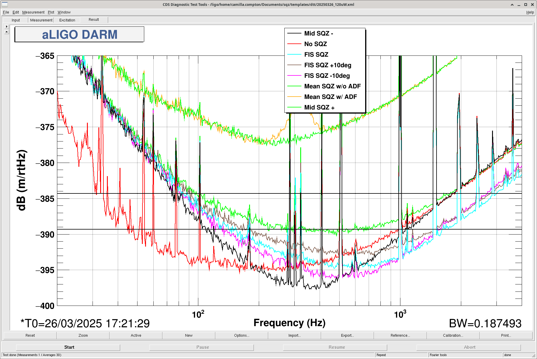
Summary: We altered the offsets on the H1:ASC_OMC_{A,B}_{PIT,YAW} QPDs which are used to align the beam into the OMC. This was aiming to give us a improvement in optical gain. After doing this we aimed to measure the anti-symmetric port light changing as we chnage the darm offset. We are trying to use both these measurements to narrow down where we have optical loss in that could be limiting our observed squeezing. Performed both measurments successfully but the different alignment of the OMC made the squeezing less good so Camilla (alog #83009) needed to do some tuning.


Last time (alog #82938) I did this I used the wrong values as our analysis used the output channels to the loops instead of the input channels which come before the offsets are put in. The new analysis of our measurement of the optical gain as seen by the 410Hz PCAL line, changing with QPD offset, shows that we want the loop inputs to change to:

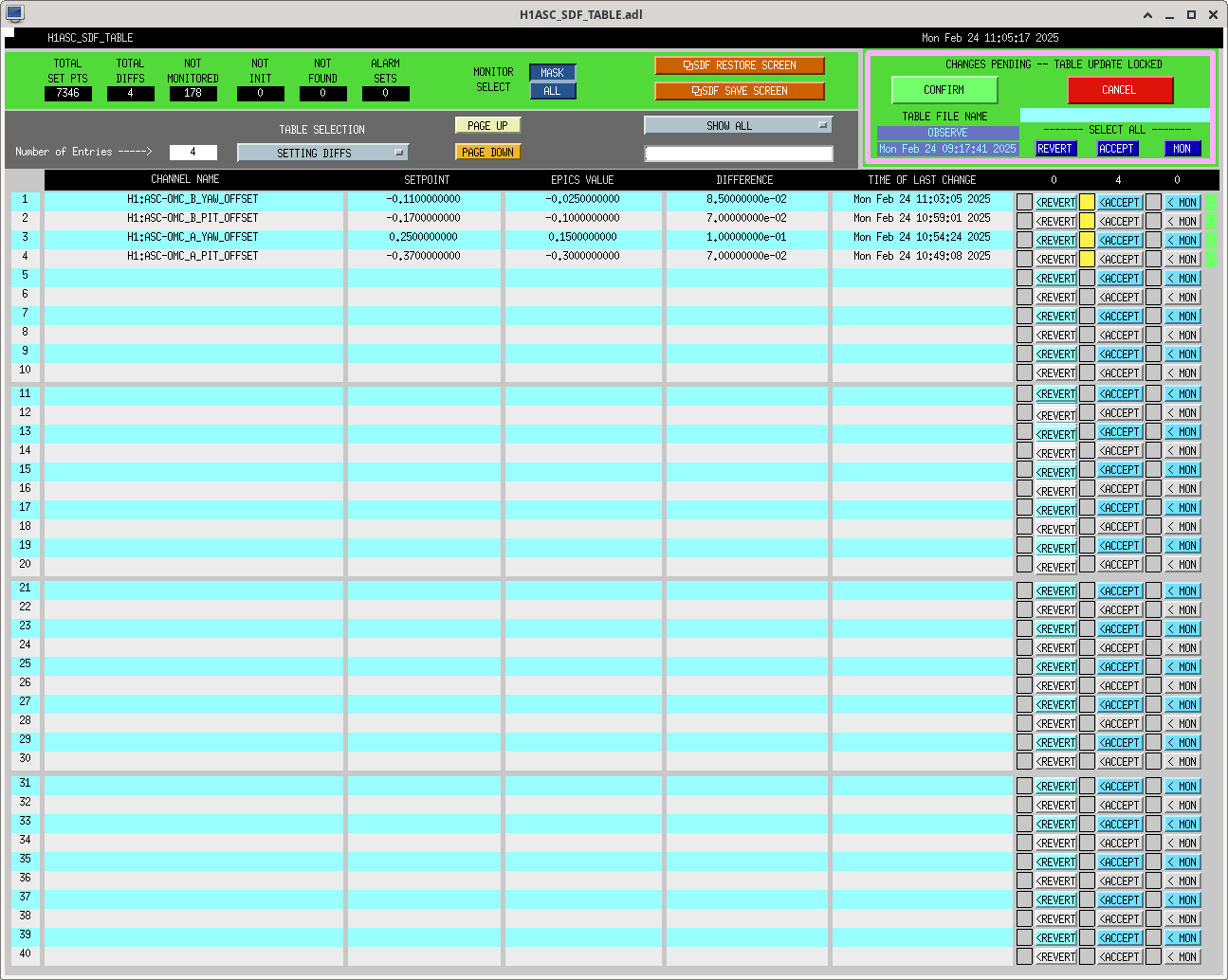
H1:ASC_OMC_A_PIT_INMON to 0.3 -> so we should change H1:ASC_OMC_A_PIT_OFFSET to -0.3

H1:ASC_OMC_A_YAW_INMON to -0.15 -> so we should change H1:ASC_OMC_A_YAW_OFFSET to 0.15

H1:ASC_OMC_B_PIT_INMON to 0.1 -> so we should change H1:ASC_OMC_B_PIT_OFFSET to -0.1

H1:ASC_OMC_B_YAW_INMON to 0.025 - so we should change H1:ASC_OMC_B_YAW_OFFSET to -0.025

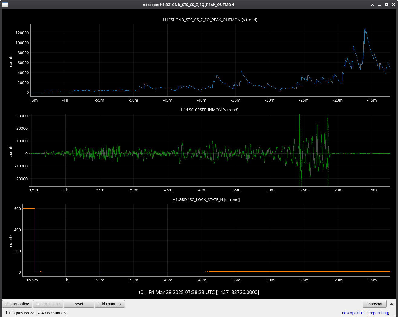
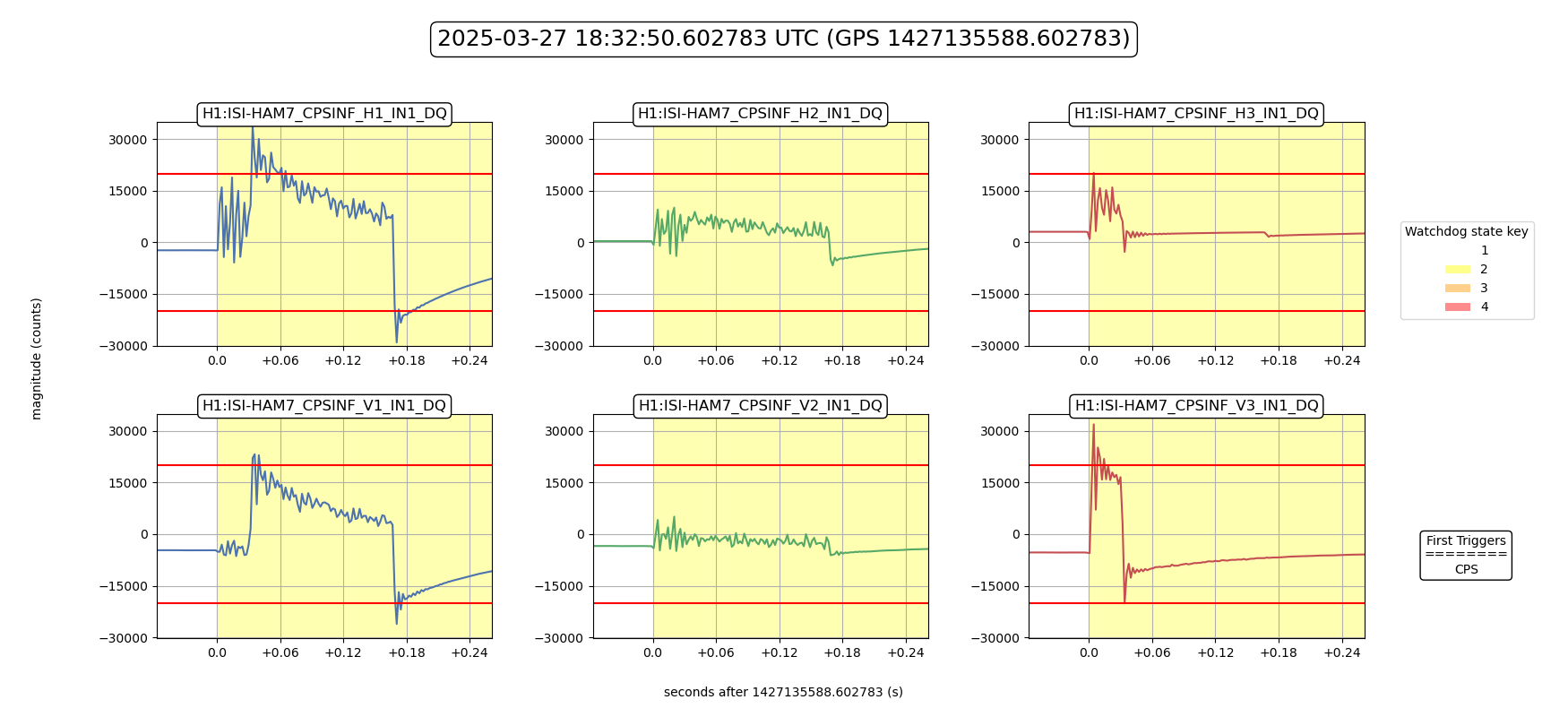
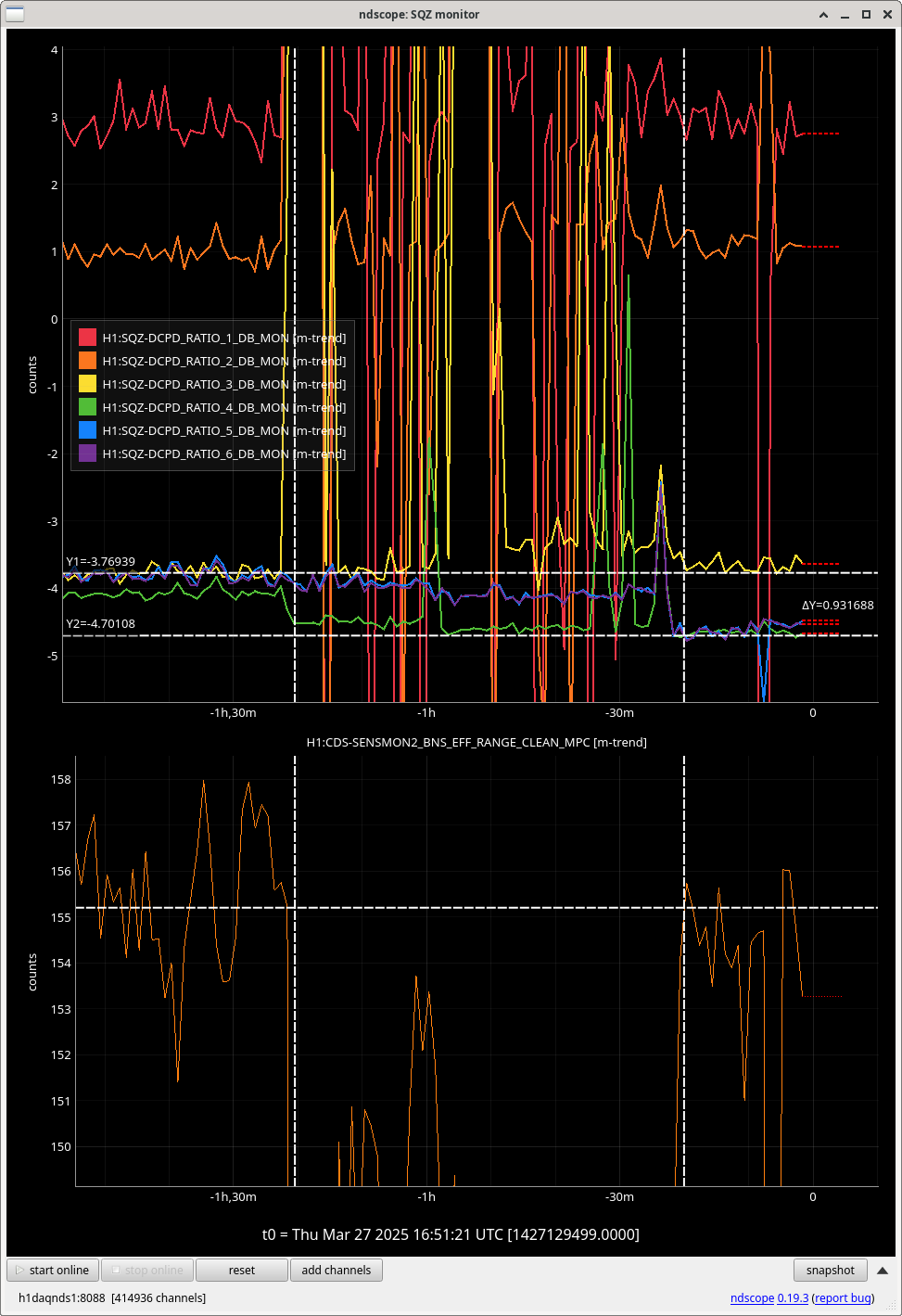
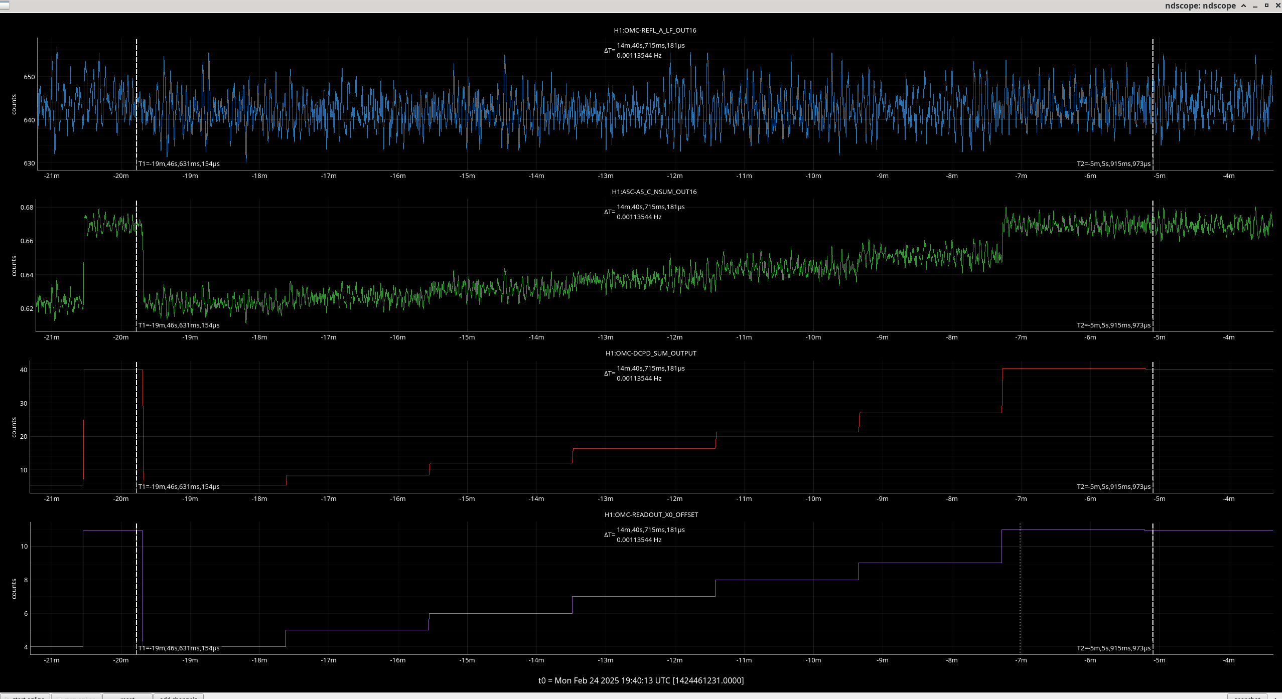
We stepped these up in steps of around 0.01 to 0.02 while monitoring the saturations on OMC and OM3 suspensions and the optical gain, both to make sure we were going in the correct direction and that we were not near to saturation of the suspensions as hapenened last time I tried to do this.

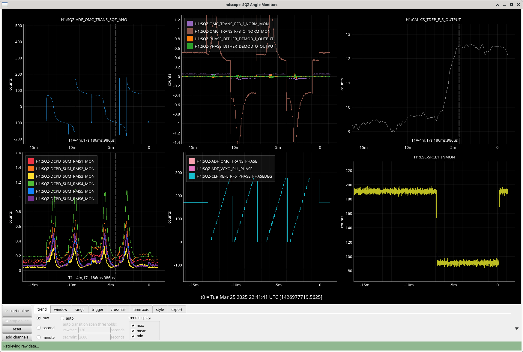
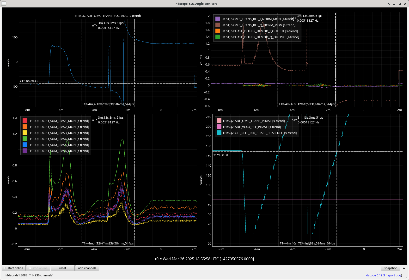
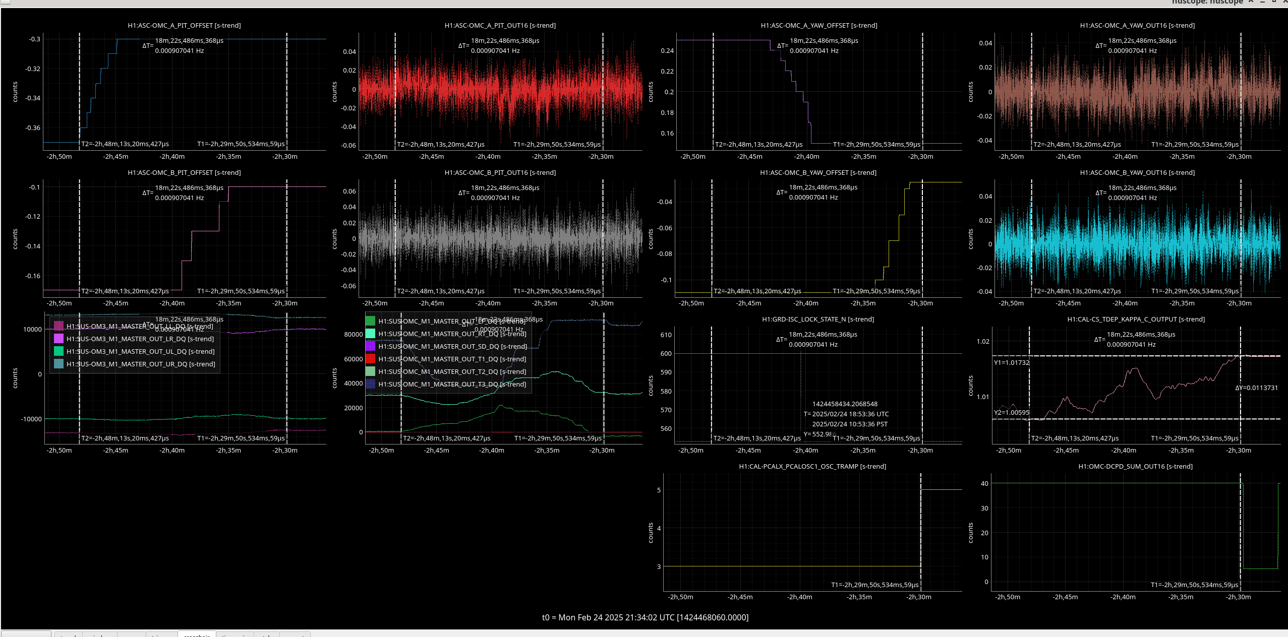
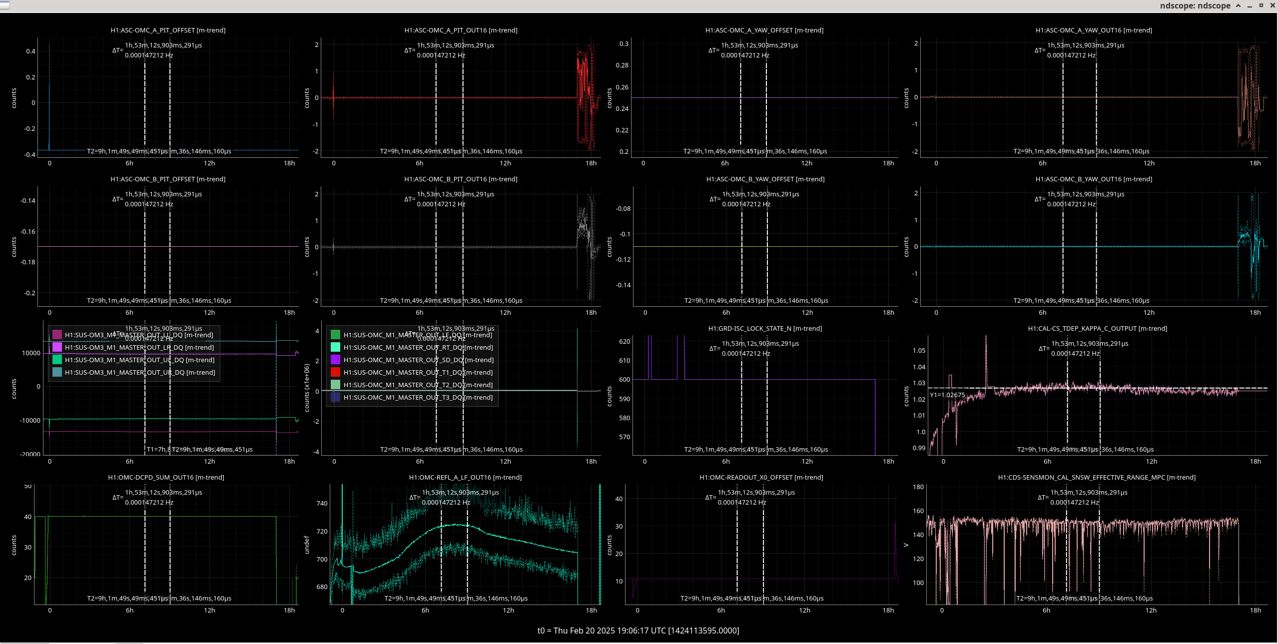
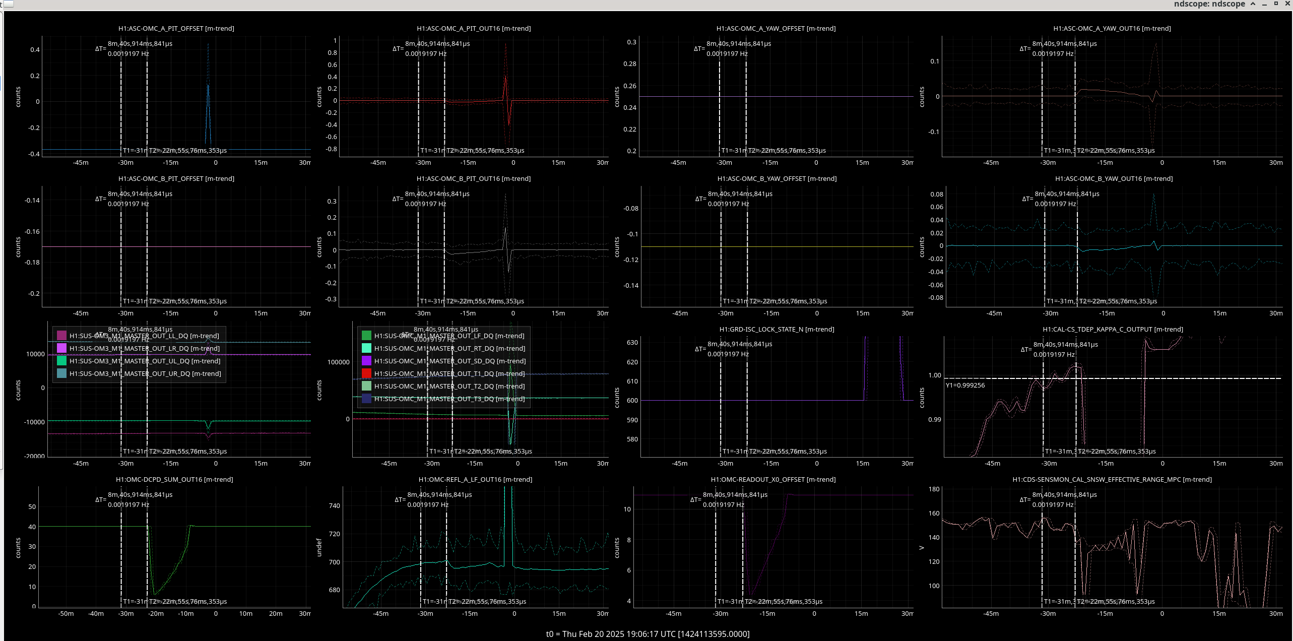
Attached is the code and the ndscope showing the steps on each offset, (top row left plot, top row center right plot, second row left plot, second row center right plot). The top stage osems for OM3 suspension are shown in the third row left plot, the top stage osems for OMC suspension are in the third row center left plot, and the optical gain is shown in the third row right plot.

The optical gain improved from by 0.0113731 from a starting value of 1.00595, so that is an improvement of 1.13 % in optical gain.


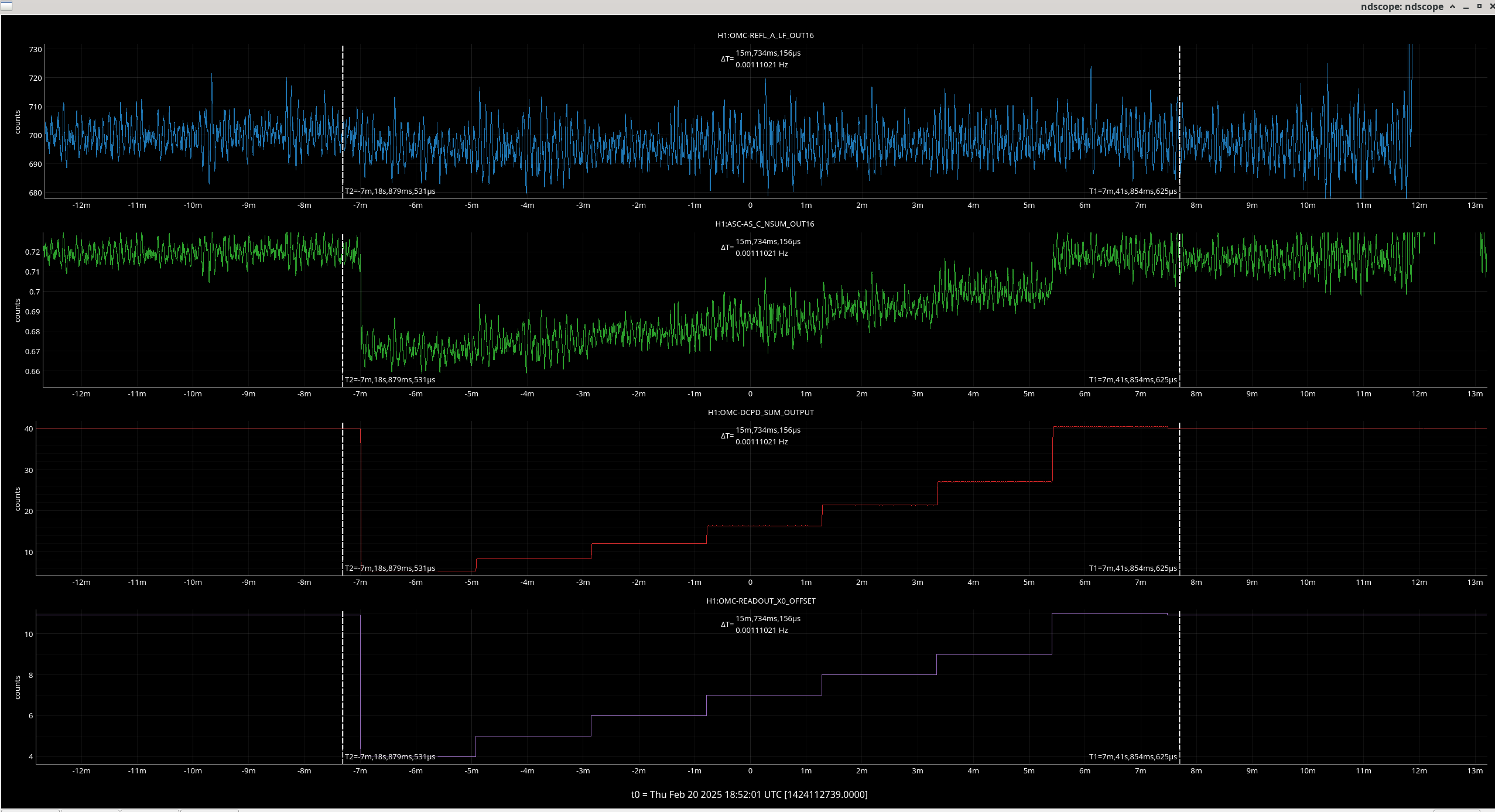
Around 19:04:28 UTC I started the DARM offset step to see if the change in optical gain matches that we would see if we measured the throughput of HAM 6. Unfortuntely I forgot to turn off the OMC ASC which we know affects this measurement of the loss. We stood down from changing the OMC and Camilla did some squeezer measurements, then I made the same mistake again the next time I tried to run it (d'oh). Both times I control-C'd the auto_darm_offset.py form the command line which means the starting PCAL line values, and DARM offset had to be reset manually before I ran the script successfully after turning the OMC ASC gain to 0 to turn it off.

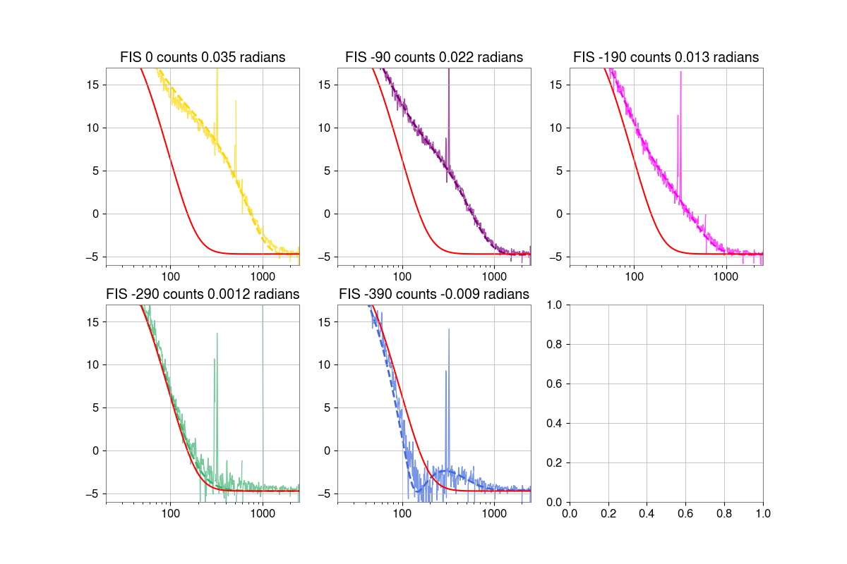
The darm offset measurement started at 19:20:31 UTC. The code to run it is /ligo/gitcommon/darm_offset_step/auto_darm_offset_step.py

The results are saved in /ligo/gitcommon/darm_offset_step/data and /ligo/gitcommon/darm_offset_step/figures/plot_darm_optical_gain_vs_dcpd_sum.

From the final plot in the attached pdf, the transmission of the fundamental mode light between ASC_AS_C (anti-symmetric port) DCPD is (1/1.139)*100 = 87.8 %. We can compare this to the previous measurement from last week with the old QPD offsets to see if the optical loss change matches what we would expect from such a change in optical gain.

Images attached to this report
Non-image files attached to this report
Comments related to this report
jennifer.wright@LIGO.ORG - 16:14, Monday 24 February 2025 (83023)OpsInfo

Since the script didn't save the correct values for pcal ey and ex (due to the script being run partially twice before a siccessful measurement). I reverted the PCAL values back using SDF before we went into observing. See attached screenshots.

Sheila accepted the new ASC-OMC_A and B OFFSET values in OBSERVE and SAFE (only have the pic for OBSERVE).

Images attached to this comment
jennifer.wright@LIGO.ORG - 11:07, Friday 21 March 2025 (83487)

Comparing OMC losses calculated by OMC throughput and optical gain measurements.

If we take the improvement in optical gain noted above and calculate the improvment in the optical gain ^2, ie.

(g_f^2 - g_i^2)/ g_i^2 = 0.023 = 2.3 %

And compare it to the gain in OMC throughput from this entry to the measurement after changing the OMC ASC offsets above

(T_OMC_f - T_OMC_i)/ T_OMC_i = 0.020 = 2%

Both methods show a similar improvement in the coupling to the OMC, or alternatively decrease in the HAM 6 losses. Since we improved the alignment of the OMC, it makes sense that the losses decrease and them agreeing validates our method of using darm offset steps to calculate OMC throughput and thus the loss in HAM 6.

The optical gain must be squared as it changes with the square root of the power at the output (due to the DARM loop).

For this comparison I was not able to use the measurement of optical gain from the same day as the initial measurement of OMC throughput, (alog #82938) as the calibration was exported to the front-end between these two dates which would have changed the reference value for kappa C.

The code I used for calcultions is attached.

Non-image files attached to this comment
jennifer.wright@LIGO.ORG - 10:29, Thursday 27 March 2025 (83587)

As I did for the previous DARM offset measurement on the 20th Feb, in alog  #83586, I checked that the DARM offset does not show a clear trend in the OMC REFL power. This would be another way of quantifying the mode-matching of the DARM mode to the OMC, but since the mode-matching is good, no trend can be seen in this channel (top plot) as we change the DARM offset.

Images attached to this comment
H1 ISC (SQZ)
jennifer.wright@LIGO.ORG - posted 12:58, Thursday 20 February 2025 - last comment - 10:30, Thursday 27 March 2025(82938)
HAM6 loss estimate remeasured with OMC ASC off

Jennie W, Sheila

Today I got a chance to redo some of my output chain measurements (alog #82555) that gave us a confusing result when we were heating up and cooling down the OM2 heater. The confusiong was that our optical gain got better for cold OM2 compared to hot, but the loss through HAM6 predicted by stepping the DARM offset and comparing it to the power at the anitsymmetric port predicted that the loss was worse with cold OM2 and gave us unreasonably low (~65 %) throughput estimate for the fundamental TM00 mode through HAM6. We realised that the OM3 and OMC alignment are being changed by the ASC during this time so that could be affecting the comparison.

Steps:

Turn off OMC ASC at 18:43:00 UTC.

Run auto_darm_offset_step.py from /ligo/gitcommon/labutils/darm_offset_step at 18:45:01 UTC.

Results: P_AS = 62.996 mW + 1.162 * P_DCPD

This makes the throughput estimate for the TM00 mode through HAM6 to the DCPDs to be 86.0 % of the power at the AS port. Which seems more reasonable than the 65% we got last time. We need to do this measurements again when we have improved kappa C somehow to check it gives us the same loss estimate between two times.


We were then going to purposely change kappa C as a comparison to the estimate the DARM offset step gives us, byt changing the QPD offsets based on this measurement 82383(I got the sign wrong last time I did this).

I turned the OMC ASC back on before doing this, however when I changed the H1:ASC-OMC_A_PIT_OFFSET to 0.45 this saturated the OM3 suspension so this was set back to nominal.

I think I got signs wrong yet again so we will try what we now think are the correct ones another commissioning period but maybe do it slowly so as not to cause saturations.


Non-image files attached to this report
Comments related to this report
jennifer.wright@LIGO.ORG - 10:30, Thursday 27 March 2025 (83048)
Images attached to this comment
jennifer.wright@LIGO.ORG - 10:21, Thursday 27 March 2025 (83586)

Jennie, Sheila

Sheila wanted me to checked that we can't use the OMC REFL power as a calculation method for how much of the TM00 light does not make it through the OMC. If the mode-matching of the light at the AS port to the OMC is good, we would expect not to see much of a variation at the OMC REFL port as we change the DARM offset, and indeed we can't. See this image, with REFL power at the top.

Images attached to this comment
Displaying reports 7001-7020 of 88198.Go to page Start 347 348 349 350 351 352 353 354 355 End