Nutsinee, Elli
Today we continued work aligning the HWS to the conjugate plane of the ETM at both end-X and end-Y.
End-Y:
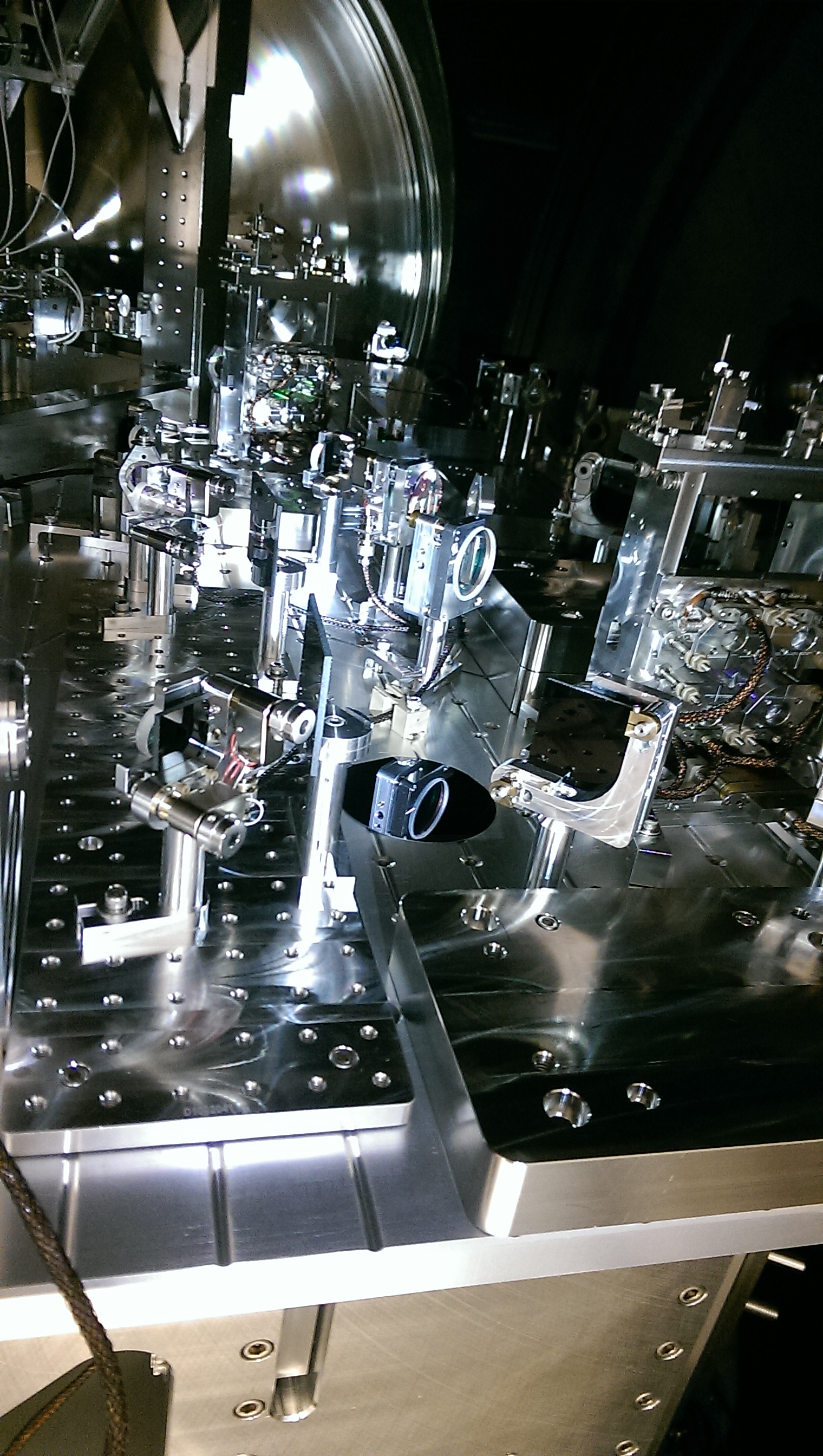
We worked on the HWS path on ISCTEY. (refer to table layout https://dcc.ligo.org/DocDB/0114/D1400241/006/D1400241_ISCTEY_H1_V6.pdf)
According to Aidan's model, the distances between lenses HWS-L2 and L3 and the between L3 and the HWS camera needed to be adjusted. We moved L3 113mm towards L2 and moved the HWS camera 108mm towards L3.
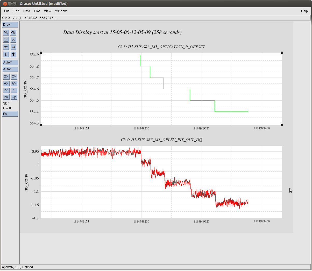
To check the location of the ETMy conjugate plane, we applyd a 0.05mHz, 2microrad yaw excitation to H1:SUS-ETMY_M0_OPTICALIGN_Y_EXC, and we measured the pk-pk movement of the beam on the HWS camera (Refer to script /ligo/home/eleanor.king/HWS_Pictures/HWS_image_plane_X and /ligo/home/eleanor.king/HWS_Pictures//find_image_plane2.m). This indicated the HWS needed to be moved an additional 30cm towards L3. To do this, we moved steering mirrors HWS-M2, M3 by 10cm, M4 and M5 by 5cm, which shortened the distance between L3 and the HWS by 30cm. (We also moved L3 again to maintain the path length between L2 and L3.)
The final distances between optics are:
L1 to L2 610mm
L2 to L3 1079mm
L3 to HWS 734mm
The HWS is sitting on the conjugate plane +/- 5cm. The HWS images showed a beam that moved around a lot, which stopped us from locating the conjugate plane more precisely than +/- 5cm. The next step is to find the source of this noise and to move the HWS to within 1cm of the conjugate plane.
End-X:
We moved L2, L3 and the HWS camera so that distances between the lenses are:
L1 to L2 610mm
L2 to L3 928mm
L3 to HWS 1396mm
This should bring the HWS to the image plane of the HWS, but looking at the movement of the beam on the HWS camera when we applied the 2micro rad yaw to H1:SUS-ETMY_M0_OPTICALIGN_Y_EXC, we calculated we needed to move the HWS by a further 0.5m. Talking to Aidan, it sounds like L1 is not in the correct position. The next step is to work out where it needs to be and move it there.