patrick.thomas@LIGO.ORG - posted 12:26, Tuesday 10 February 2015 (16597)
Updated conlog channel list
Added 26 channels. Removed 105 channels.
Added 26 channels. Removed 105 channels.
No Issues at restart, no impact on HEPI Platform.
SDF updated, foton file committed to svn.
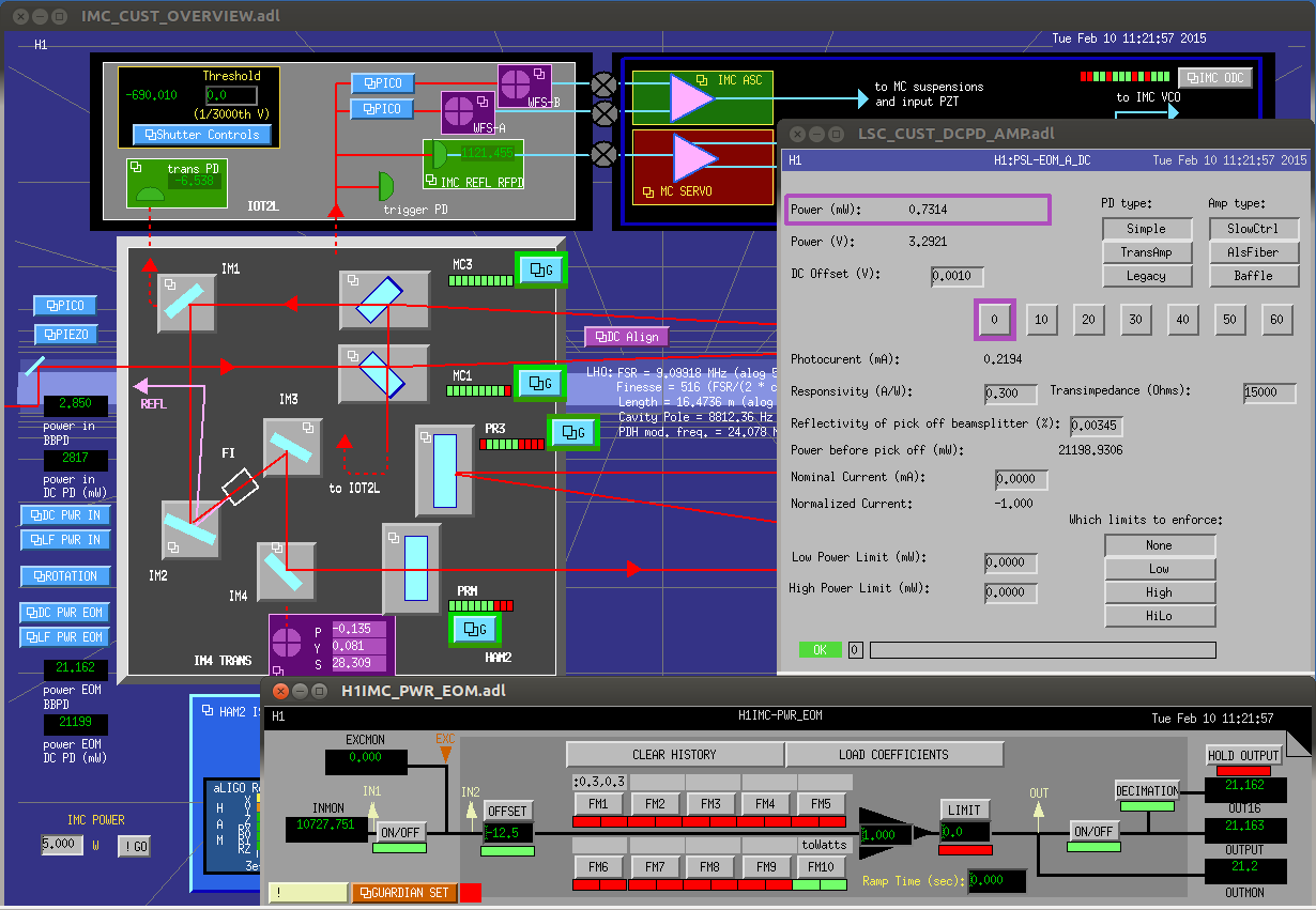
The PSL team has installed an ND filter in front of the IO photodiode measuring the power after the EOM. Now we have about 3V. I adjusted the calibration to give us 21W. Old alog at 16437. I added the power readbacks to the IMC overview screen as well.
Summary:
ETMX M0 stage was pushed towards the reaction chain so the F1 flag comes out of the BOSEM. It got slightly better, BOSEM reading changed from 7300 to 8300.
Reaction chain was pushed away from the test mass chain so that L1 and L2 stages don't get too close to the test mass chain.
We don't know yet if this made any change to the damping etc.
Details:
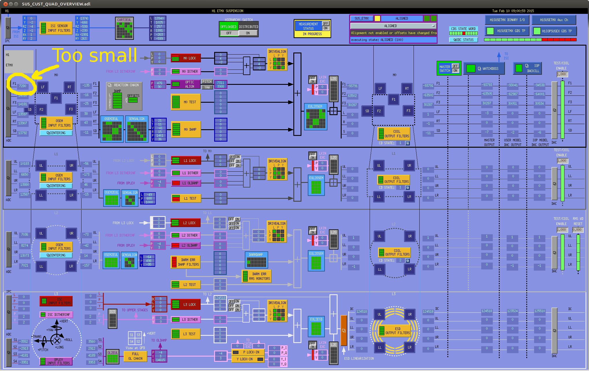
Due to a huge pit offset we need to align ETMX (it was large before the vent, but it got worse after), F1 flag is too much into the coil, and supposedly that is one of the reasons why the PIT damping is not that good. In the first attachment, you can see the BOSEM reading of F1 to be about 7300 (ideally this is 16000 or so).
I gave the top stage a length push such that the test mass chain is pushed away from the top face BOSEMs, and gained about 1000 counts in F1 BOSEM. With this offset the coil outputs should still have some headroom even if you misalign the ETMX to point to baffle PDs.
One drawback of this is that the test mass chain is pushed towards the reaction chain, which is fine under a normal circumstances, except that Sheila tells that misaligning the reaction chain of ETMX affected the actuation behavior of L1 and/or L2. I'm worried that something is close to touching, and pushing flags further into OSEMs doesn't sound like a good idea.
So I gave a length offset to the reaction chain, pulling it back from the test mass chain.
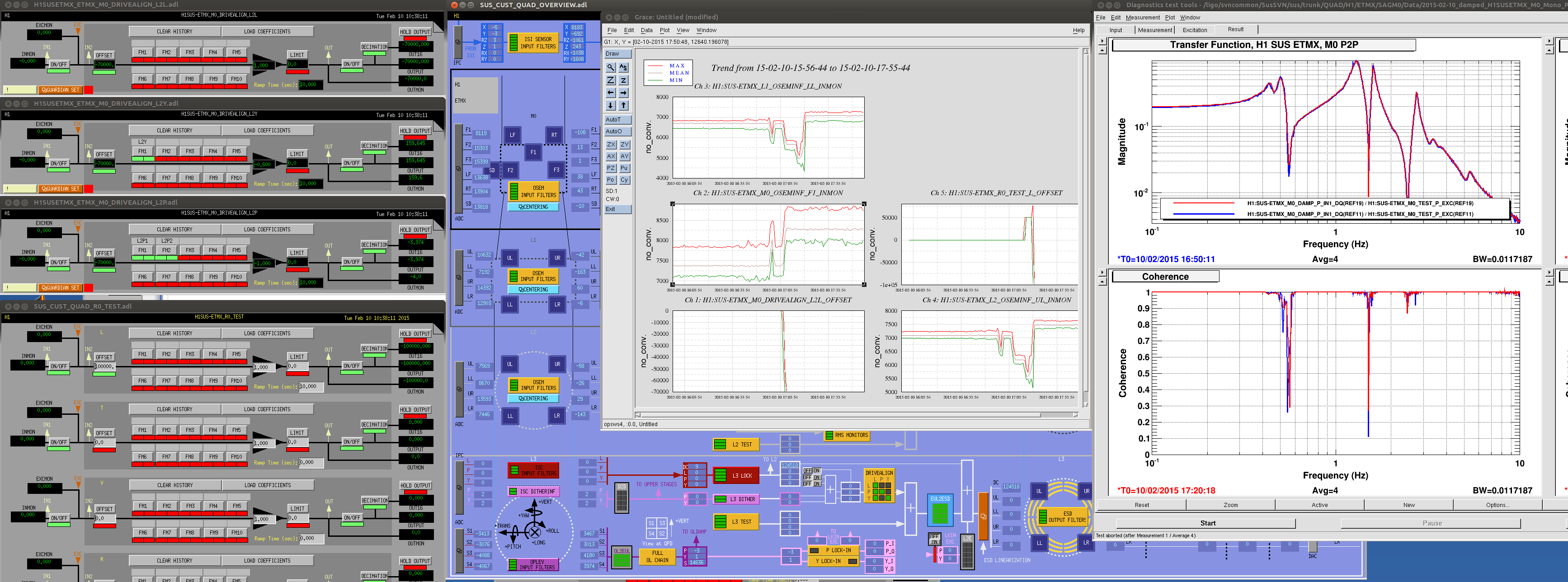
In the second screen shot you can see that I gave offsets to L2L, L2Y and L2P drivealign matrix rather than M0_LOCK_L because of a very small DC gain of the latter, and because it's somewhat more convenient than to give length offset to TEST_L and compensate the misalignment caused by that by using alignment sliders.
If this makes no negative impact on locking, the offset could be moved to TEST_L and sliders.
Reaction chain offset H1:SUS-ETMX_R0_TEST_L_OFFSET was set to -100k. I can go further easily, but I left some headroom so the reaction mass could be misaligned when fringe wrapping between the test mass and the reaction mass is observed.
After these, M0_OSEMINF_F1_INMON changed from 7300 to 8250, L1 LL from 6700 to 7000, L2 UL from 7100 to 7500.
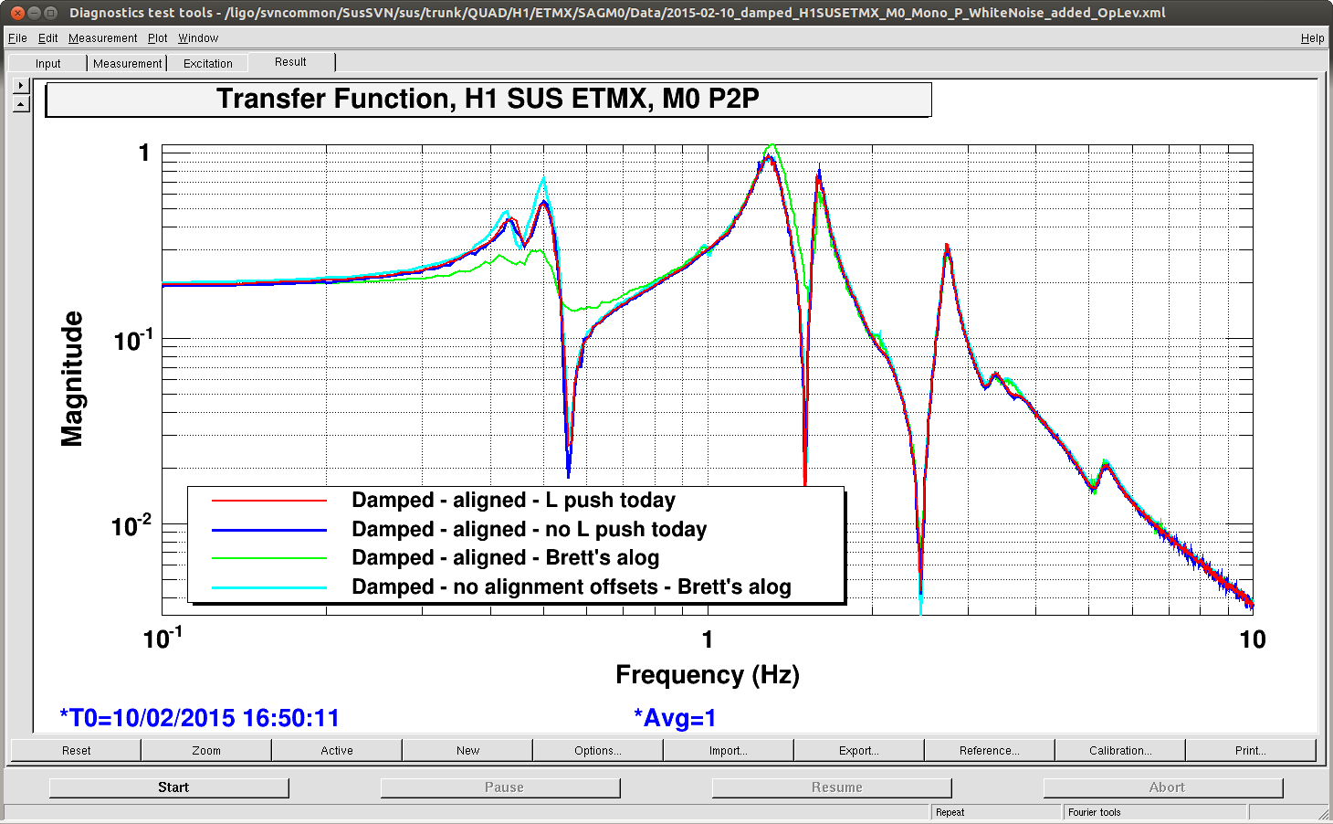
I took a very very quick top P2P TF of the test mass chain for before(blue)/after(red) comparison and I see no ill effect (but no difference means no change in the PIT sensing). This comparison was done without oplev damping.
Just a reminder for some history on the problematic pitch damping of ETMX: I investigated the effect of the alignment offsets on pitch damping last month. See 16107. I plot some pitch TF measurements from the morning of Jan 16 that suggest the pitch offset influences the OSEM sensitivity around the first two modes. However, a repeat measurement that afternoon was completely normal, i.e. no influence of the alignment offset at all.
Don't know what this means. It's possible the damping problem is not due to the alignment and what I saw was something else mysterious. Or maybe it comes and goes, which sounds worse to me.
When I compare today's measurement with Brett's (alog 16107), the TFs today are somewhere between his good data (cyan) and bad one (green), somewhat closer to the good than the bad.
Anyway I'll leave the reaction chain offsets on because of the claim about reaction chain misalignment VS the actuation of L1 and L2, and the test mass chain offsets on because of the same possibility as the L1 and L2 (that the flags are very close to hitting something, making them hit when driving hard).
ETMx and ETMy ring heater chassis have been turned on. I have copied the ITM calibration settings (except for resistance values) over to the ETMs. I breifly turned each heater on and off again, they are drawing the right ammount of power. All of the ring heaters are requesting 0W (ie no heating) right now.
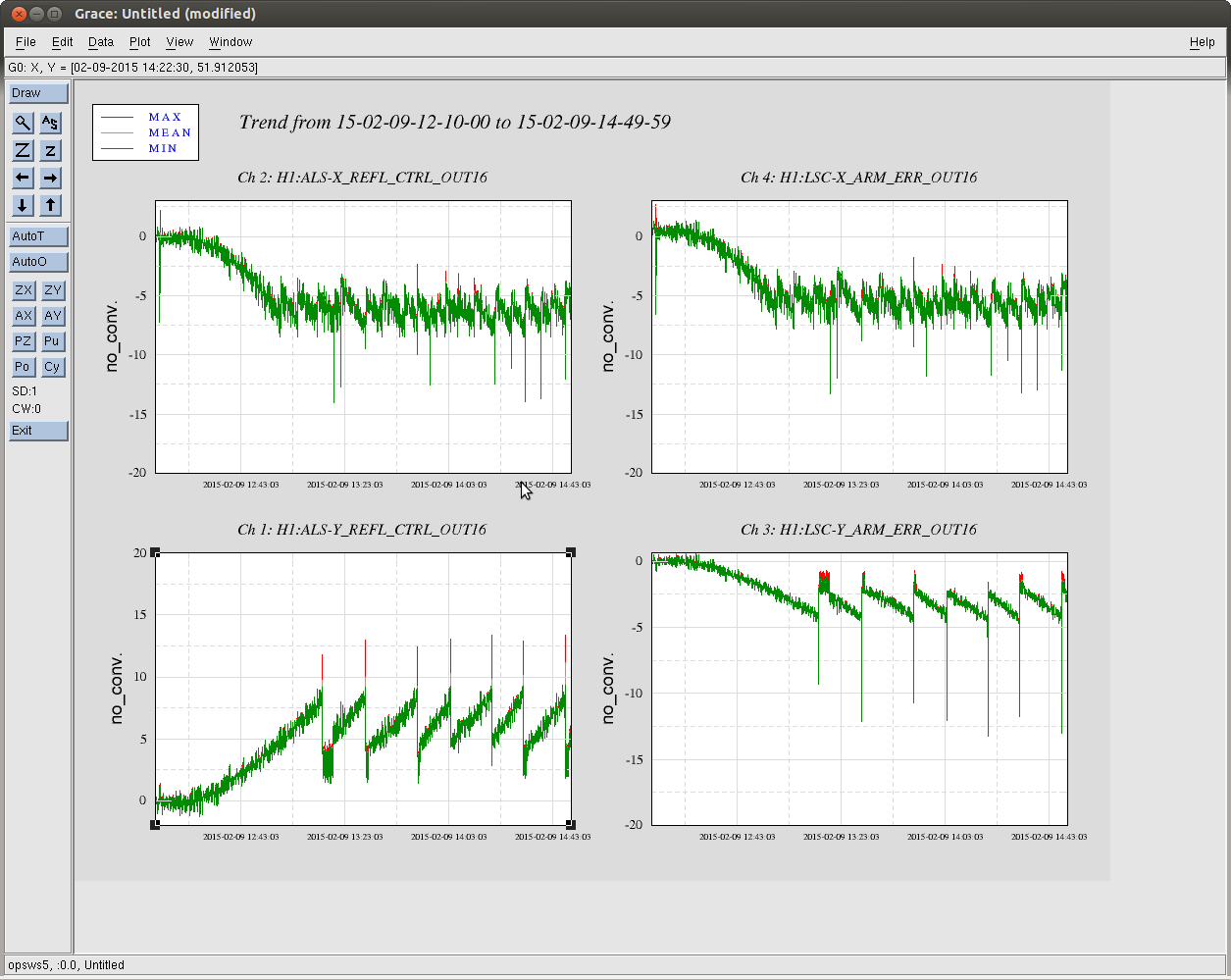
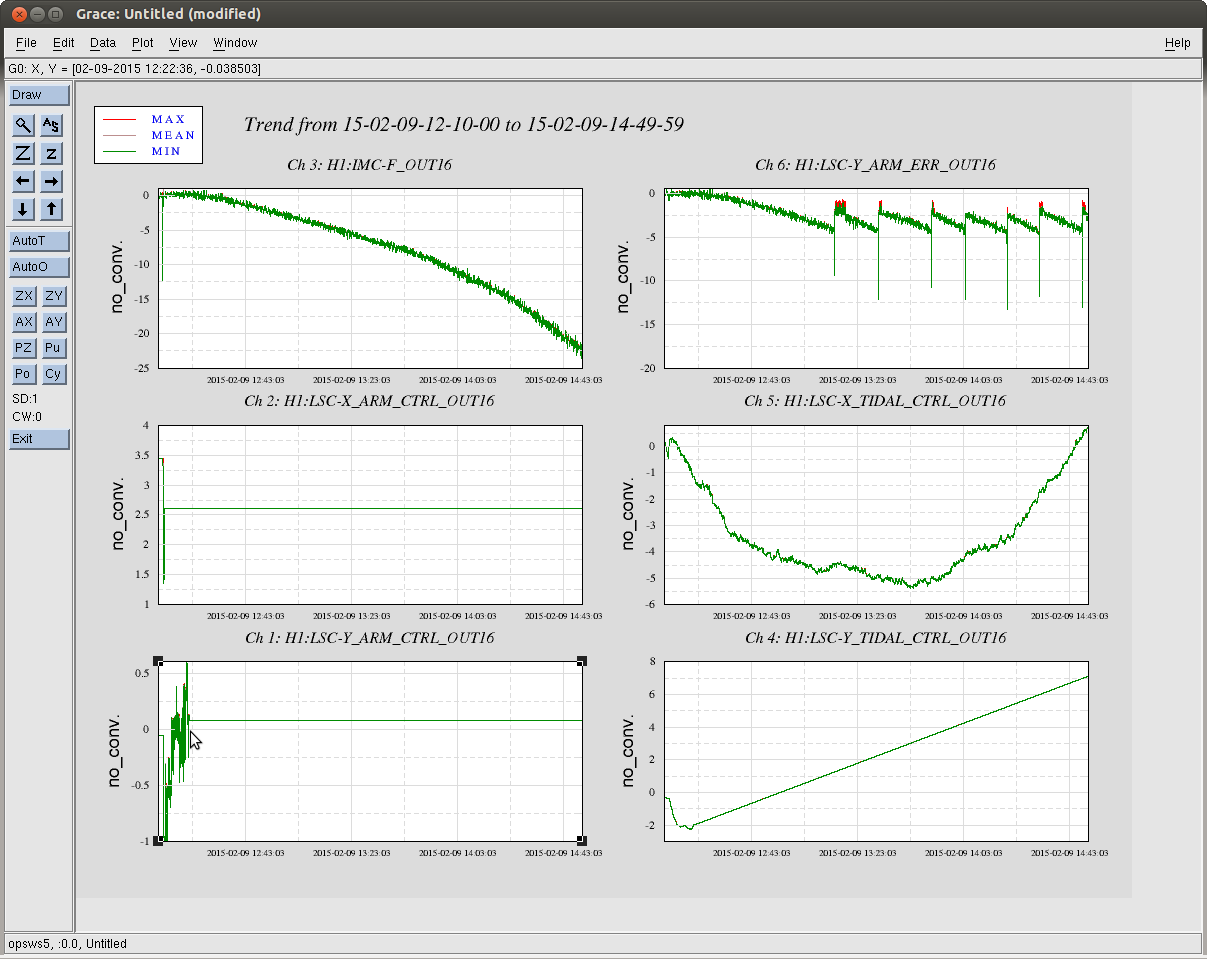
Looking at the tidal feedback signals during the 2 hour lock shows:
Script:
#!/usr/bin/python
import ezca
Ezca=ezca.Ezca("H1:")
while True:
    val=Ezca['IMC-F_OUT16']
    Ezca['LSC-X_COMM_ERR_OFFSET']=val
    Ezca['LSC-Y_COMM_ERR_OFFSET']=val
Changed the H1:ALS-Y_REFL_SERVO_IN1GAIN to -7dB (from -13dB) and H1:ALS-Y_REFL_SERVO_FASTGAIN to 0dB (from +6dB). Also turned on the frequency servo for the VCO on in EY.
Alexa Dan Evan Lisa Sheila
Today the ETMY bounce mode was ringing up during our many lock attempts. We rediscovered Nic's work to damp this mode using DARM feedback to the pitch drive of ETMY L2. We have been able to damp the mode while hanging out in ALS_DIFF, but progress is slow. We suspect that the high noise floor of DARM when locked on ALS_DIFF is limiting our ability to damp the mode. Transitioning to RF DARM may let us damp the mode more quickly, but this carries it's own inconvenience.
Anyways the way to damp the mode is to enable ETMY L2 DAMPDARM MODE1 --> PIT, with FM1-3 turned on. (FM3 is a 206dB gain stage, I have never seen so many dB in one place before.) With the bounce mode very high we had to reduce the overall filter gain to -0.04 to keep the SUS L2 drive from saturating. (Nic recommends -1, probably this is good once the mode has damped a little.)
- Dan as Sheila
Evan, Lisa, Sheila, Dan, Alexa, Kiwamu
With DARM on ASAIR_RF45_Q and CARM on analog REFLAIR_RF9_I at zero CARM offset, we were able to transition the DRMI 3f signals from REFLAIR_B to the 1f POPAIR_B signals.
The locking sequence is scripted in the guardian up until this point.
By exciting PRM, we adjusted the demod phase of POPAIR_B_RF9 and POPAIR_B_RF45. In both cases we maximized the I signals, and found 66.6º and -30º for RF9 and RF45 respectively. Then, we excited PRM, SRM, and BS at 137 Hz, 137 Hz, and 53 Hz respectively. The folder /ligo/home/alexan.staley/Public/Spectra_3F2POP contains the DTT files, which have the power spectra for all the POPAIR_B signals, as well as transfer functions to the respective REFLAIR_B signals. The input matrix is as follows:
| POPAIR_B_RF9_I | POPAIR_B_RF45_1 | POPAIR_B_RF45_Q | |
| PRCL | 0.27 | 0 | 0 |
| MICH | 0 | 0 | 0.54 |
| SRCL | 0.041 | 0.74 | 0 |
When locked with the POP signals, we measured all three loops and found that they were all at the appropriate UGFs with good phase.
This morning, the IMC had a difficulty in relocking it.
It turned out that most of the IMCASC DOFs had accumulated some large offsets which had pushed the alignment so bad that it was not able to catch a 00-mode. This was due to the fact that we had turned on both the offsets (e.g. IMC-DOF_1_P_OFFSET) and the integrators, which off course simply accumulated the offset in the up front even when the IMC was unlocked. I disabled all the offsets as they are not necessary for now.
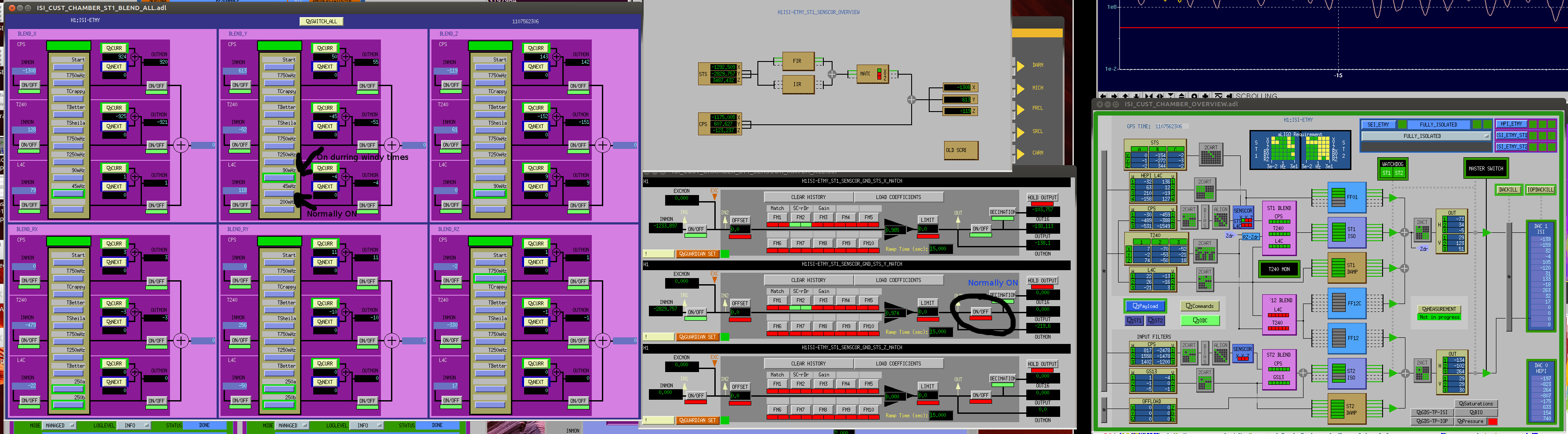
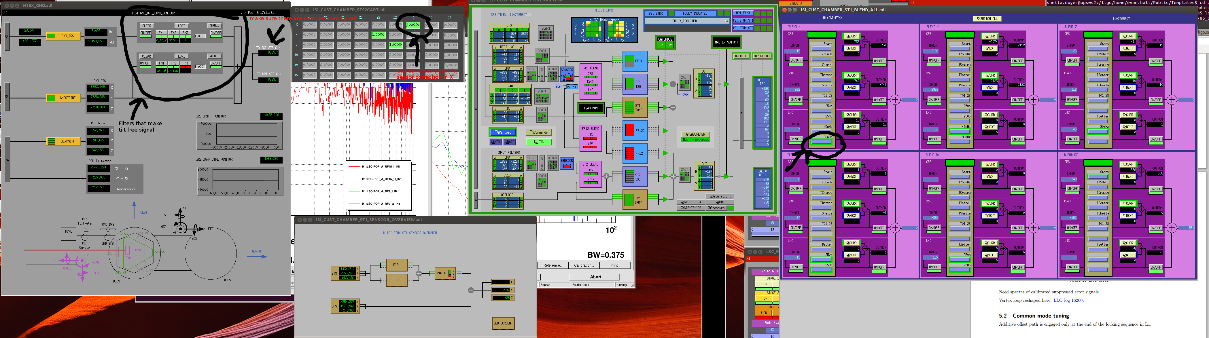
Over the last few days, we have been occasionally been locking the ISI to the position sensors below 90mHz along the beam direction when the wind is high.
The general idea is that wind causes the ground to tilt, at low frequencies this shows up as a huge translational signal in the interial sensors, so we are better off controlling the ISI with position sensors to higher frequencies when the wind is high. This means that we give up some isolation at the microseism, so it might not be a good idea to do this when the microseism is high. The last few days the 0.1-0.3 Hz BLRM has been hovering around 0.4 um/sec, in this situation blending high along the beam direction when the wind is steadily above 20 mph seems to help us.
I've attached a screen shot of the configuration that I've just switched the Y end to, this only takes two button clicks, switch the Y blend from 45 mHZ to 90 mHz, and turn off the output of the sensor correction in the Y direction.
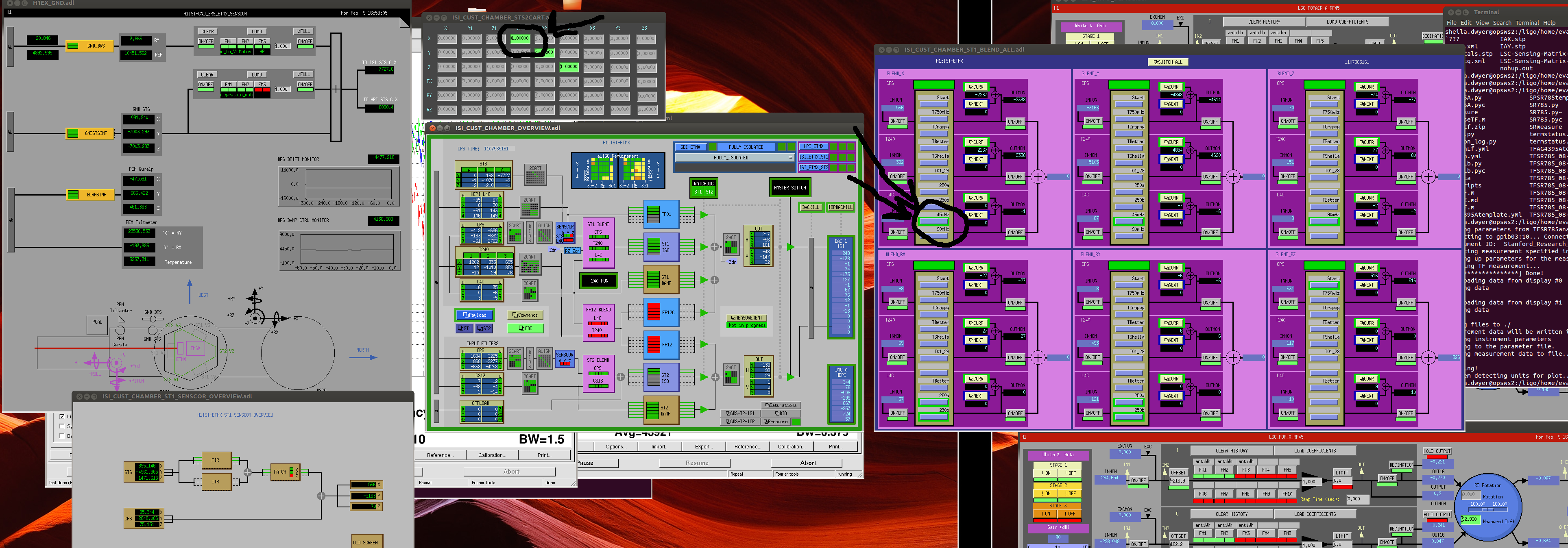
At X end we have been doing the same blend switching along the beam direction, but here we have the BRS, which can be used to subtract the wind induced tilt from the ground seismometers so that sensor correction can give us some benefits even durring windy times. So the X end procedure is three clicks: raise the X blend to 90 mHz, turn off the unocrrected X sensor correction by typing zero in the ISI_CUST_CHAMBER_STS2CART screen at the X X2 position, then turn on the corrected sensor correction by typing a 1 in the X X3 position. Before and after screen shots attached.
7:00 Jodi to LVEA West Bay
7:30 Mitchell joined Jodi
8:15 Aiden to LVEA
8:45 Bubba to LVEA (checking on 3IFO containers)
8:45 Karen to End Y
8:45 Thomas and Sudarshan to End Y (PCal)
9:15 Corey to Mid-Y
9:37 Jodi and Mitchell back
9:40 Karen left End Y
9:47 Bubba back from LVEA
9:49 Corey back from Mid-Y
9:53 Rick to LVEA (for a few minutes)
10:01 Thomas and Sudarshan back
10:10 Aiden to High bay
~12:30 DRMI locked, commissioning started
A fire truck came in and went to Mid Y at one point in the afternoon (forgot to write down the time, my bad). Nothing was on fire.
~ 4pm, another lock (Hooray!)
This morning I turned on HEPI feedforward to BSC St1 on all of the BSC's. I took measurement as I went, generally improvements between 5x and 10x, between 1 and ~10 hz. The attached plot from ITMY is one of the better ones, but typical. Green is the ground, black is before, red is after. I still have to get some time to bring down FF to get some gain matching measurements, but I can probably fit this in on some morning before the commissioners come in.
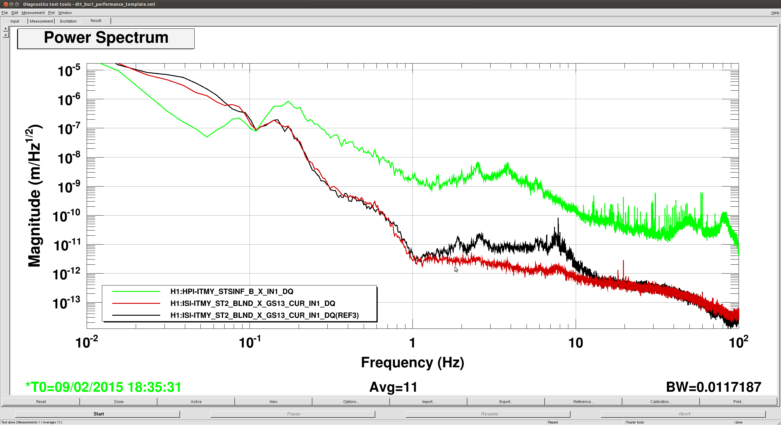
Will load these tomorrow & correct sdf
Laser Status:
SysStat is good (except VB program online = known issue)
Output power is 32.4 W (should be around 30 W)
FRONTEND WATCH is Active
HPO WATCH is red

PMC:
It has been locked 20 day, 2 hr 23 minutes (should be days/weeks)
Reflected power is 2.1 Watts  and PowerSum = 25.3 Watts.
(Reflected Power should be <= 10% of PowerSum)

FSS:
It has been locked for 7 h and 17 min (should be days/weeks)
Threshold on transmitted photo-detector PD = 1.12 V (should be 0.9V)

ISS:
The diffracted power is around 5.4 % (should be 5-15%)
Last saturation event was 7 h and 19 minutes ago (should be days/weeks)
Sheila, Alexa, Evan
We have transitoned CARM from digital normalized REFLAIR9I to analog REFLAIR9I, with a 4 kHz bandwidth and 50 degrees of phase. An OLTF is attached [the last data point is spurious, so ignore it]. This lock started at about 2015-02-09 12:24:00 UTC. We are leaving the IFO locked.
There is plenty of phase to push the bandwidth higher, but we have encountered large offsets induced by switching on the common-mode and summing-node boards.
We can also improve the low-frequency fluctuations of the CARM error signal by introducing an integrator somewhere; we need more dc gain.
Analog REFLAIR9I is plugged into input B2 on the summing-node board (SNB), with polarity "off". The output of B goes into input #2 on the common-mode board (CMB), with positive polarity. Digital normalized REFLAIR9I is plugged into input A1 on the SNB, with polarity "on". The output of A goes to input #1 on the CMB. [See LHO#16489 for a review.]
According to our reckoning, the shape of the digital CARM loop at the start of the transition is roughly 1/f above a few hertz. At a few hertz and below, it has a number of boosts and integrators which make it tricky to engineer a stable crossover with the analog signal.
Transition procedure is as follows, starting right after the guardian has brought the interferometer into resonance.
Also, the use of DHARD WFS (pitch and yaw) has removed the need for touching up the ETMs. However, since the AS36Q WFS feedback to the BS has not worked for the past couple of days, the BS had to be touched up by hand every so often.
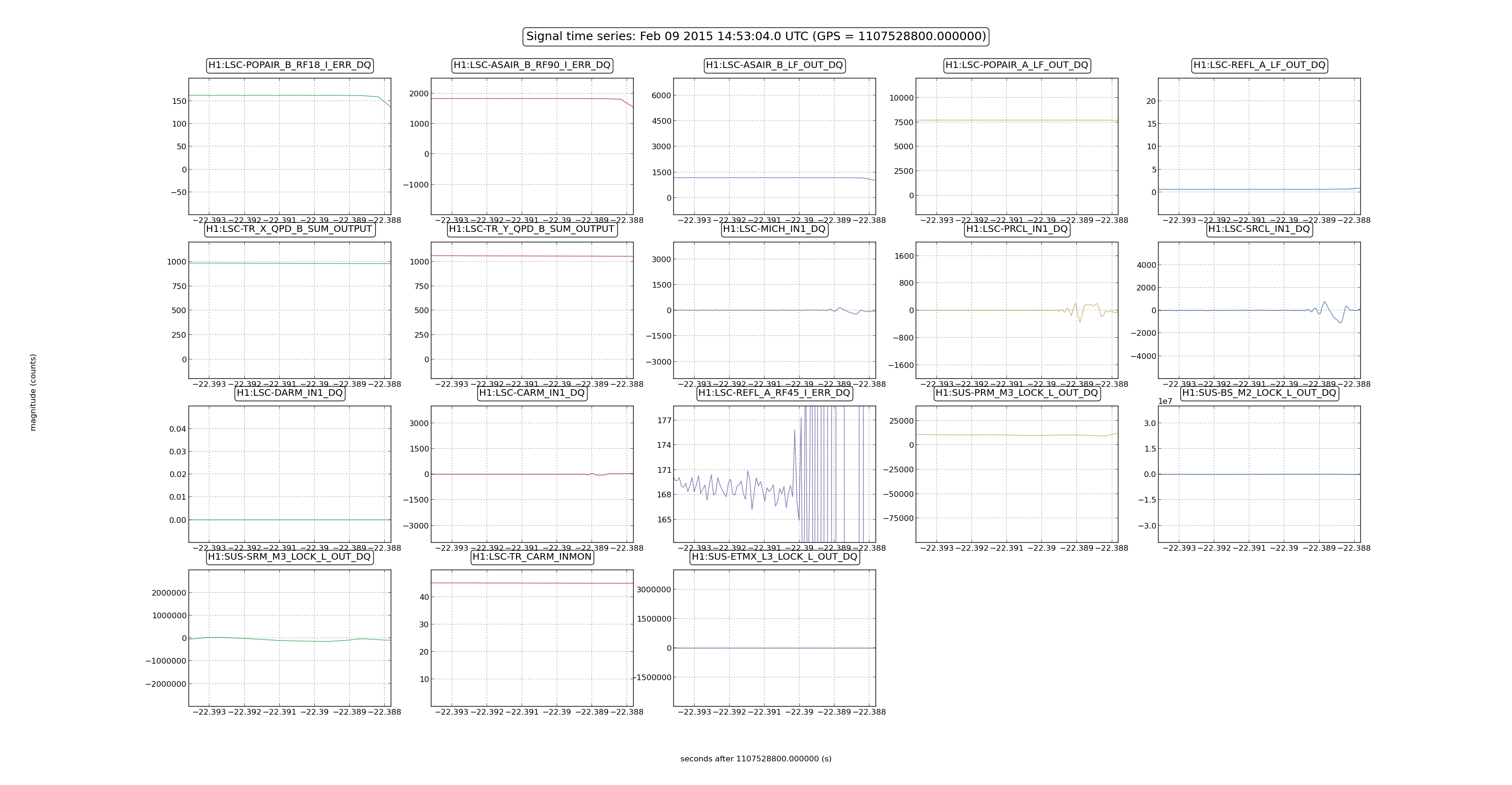
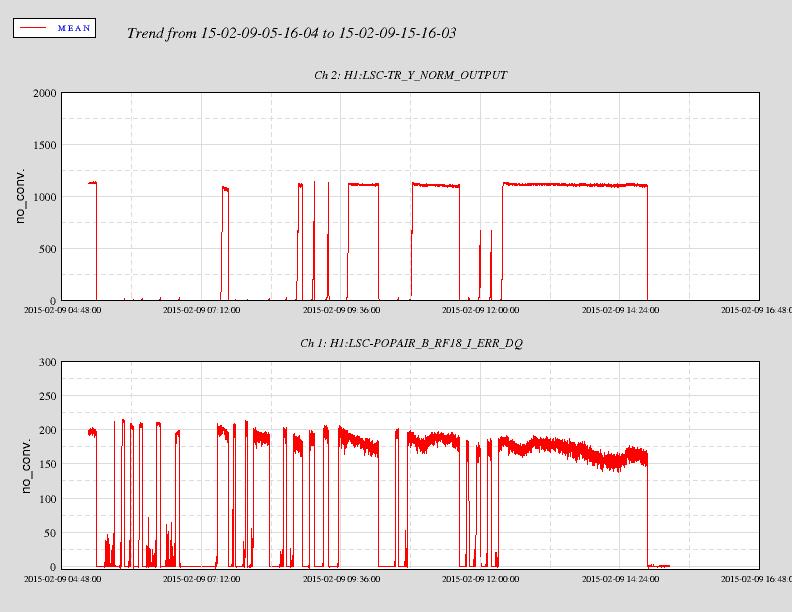
In fact this lock lasted about 2.5 hours.
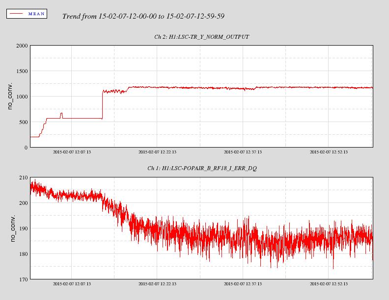
The lock broke due to a ~ 5kHz oscillation in the CARM loop (first plot).

The second plots shows several locking attempts from last night. The drop in the sideband power observed during  the first long lock last Friday , correlated with the increase of the carrier build-up during acuqisition, is not present anymore now that the locking sequence is much faster, so it might have been some thermal-induced effect.

The third plot shows the trend of the power recycling sideband and carrier power, whose fluctuations are well correlated with angular PIT motion of the BS (ASC BS loops not yet closed, as Evan was saying).
Here are some numbers for arm buildup on resonance, recycling gain and stored arm power for last night's lock:
-IMC input power was 2.81W. Given modulation depths of Γ9 = 0.219(12) and Γ45 = 0.277(16), from alog 15674, the power in the sidebands is (Γ92+Γ452)/2=6%, there was 2.64W carrier power into IMC. 88% of this power is transmitted through the PSL-IMC-Faraday chain to PRM as measured in alog 13495.
-Arm buildup (X-arm) was 1200 x single arm power (1210 at the beginning of the lock). LSC-TR_X_QPD_B_SUM_OUTPUT was an average of 1035(10) cts during the lock stretch. This QPD is already roughly calibrated to arm buildup, but can be corrected for new input power levels as per Evan's alog 16450, so [arm buildup]=TR_X_QPD_B_SUM_OUTPUT*(10.95/2.82)*(3/10).
-Recycling gain was 36 W/W. [Recycling gain]=[arm buildup]/[PRM transmissivity], assuming PRM transmissisivty of 2.97% from galaxy page.
-X-arm cavity gain is 276 W/W. G_arm=( ti / (1-ri*re) ) ^2. Transmissivities Ti=1.39% and Te=3.6ppm according to galaxy webpage. re=sqrt(1-Te-Le) where Le is the x-arm loss is assumed to be 120(30)ppm based on alogs 16082, 15937, 15919.
-Power stored in the X-arm was 11.5kW. P_arm=[carrier power into PRC]*[recycling gain]*[0.5 (beamsplitter)]*[arm cavity gain]=2.64*0.88*36*0.5*276.
I made a typo in the equation for recycling gain, which should read: [Recycling gain]=[arm buildup]*[PRM transmissivity]
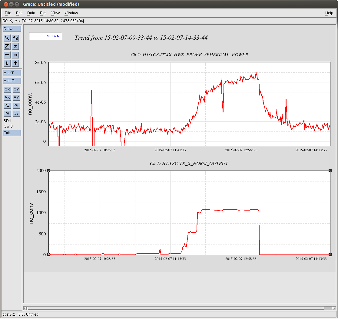
The HWS on ITMX was running during last night's 1 hour lock. It saw a lens of ~6 micro-diopters (double-passed) form while the IFO was locked. The transient data is in the attached plot.
HWSY is not currently operational.
At the moment, I can't reliably estimate the absorption coefficient, but the absorbed power is about 1.06 mW per micro-diopter (double-passed), so roughly 6mW of power was absorbed.
If I go with 2W requested from the PSL rotation stage and do the same calculation we did at LLO:
2W (input power) * 30 (recycling gain) * 0.5 (beam splitter) * 286 (arm cavity gain) = 8.6kW stored arm power,
which yields
I would definitely take this number with a healthy grain of salt ... I'd still like to run some diagnostics on the ITMX HWS following yesterday's code update.
(Also, the data in the attached plot was rescaled in dataviewer, by 0.00326, to what is currently displayed to account for the fact that the HWS magnification was set to 1x at the time of this measurement, rather than 17.5x. The spherical power scales as 1/M^2 = 1/17.5^2 = 0.00326).
I've added this data to the TCS actuator couplings document on the DCC.
I've calculated the stored arm power from last night's lock as 11.5kW (As calculated in post 16579).
Using this number instead of 8.6kW approximated from livingston's numbers, this brings the estimate of absorption in the ITMX coating to 520 parts per billion.

