So what was supposed to be a simple favour for Aidan to turn the CO2y laser on turned out to be not so simple. Note: when I started this work I was unaware of the issues that Greg encountered last week (he has just put in an alog now for me alog 17302).
So at the moment the CO2y laser is still off.
Below is what observed/thought was the problem before hearing from Greg about the issues he saw previously (and is now alogging) , and also talking to Aidan about his recollections. Also will include what I think is going on for part of it and also recommendations.
Observation 1:
The rotation stage for CO2y is not working (I cant get it to do any rotation of any kind). I played with this before knowing that Greg had seen this last week also. I did not try playing with the CO2x. Based on past experience at LLO and LHO its going to be something with Beckhoff having to be reset (we really need to work out why these things just stop working). So until it is up and running I dont want to turn the laser on. And because I dont know how LHO like to proceed with doing procedures like this I took this no further. So what I need is for someone (maybe at start of next weeks maintenance period) to reset the HWP for me (probably just needs to be unplugged then replugged).
Observation 2:
I went out to the mechanical room to check the status of the power supplies etc. I immediately saw two things that peaked my interest.
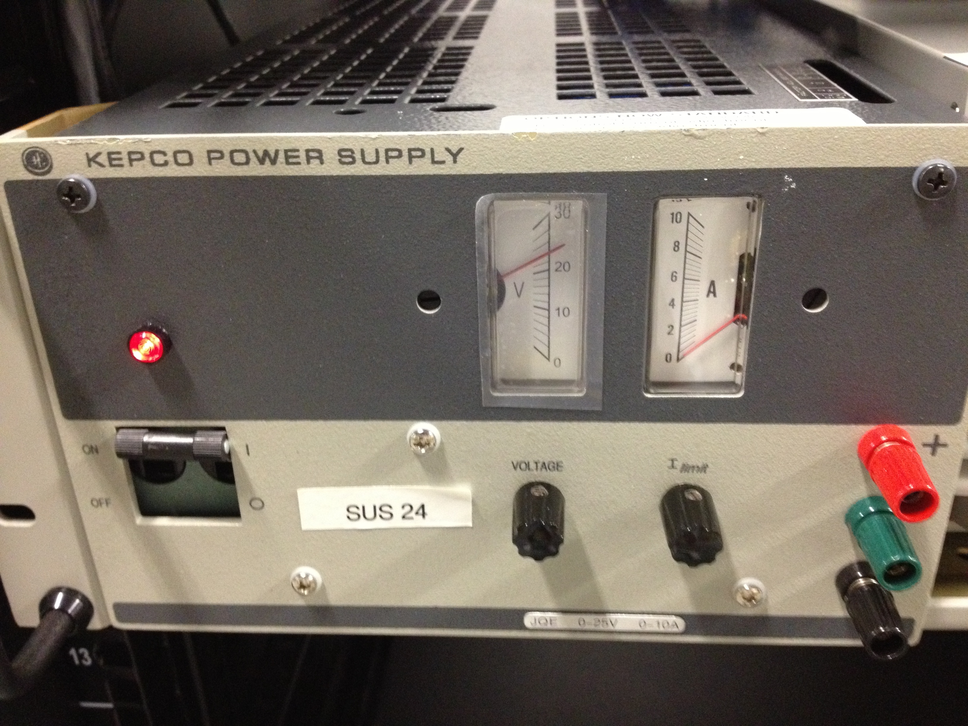
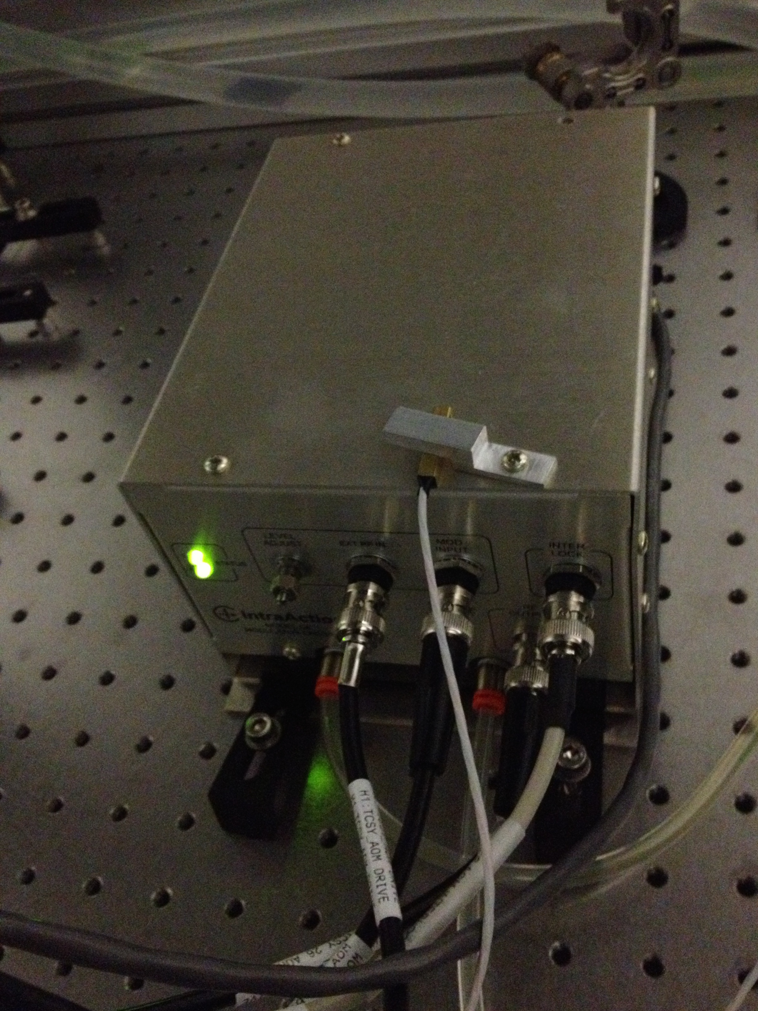
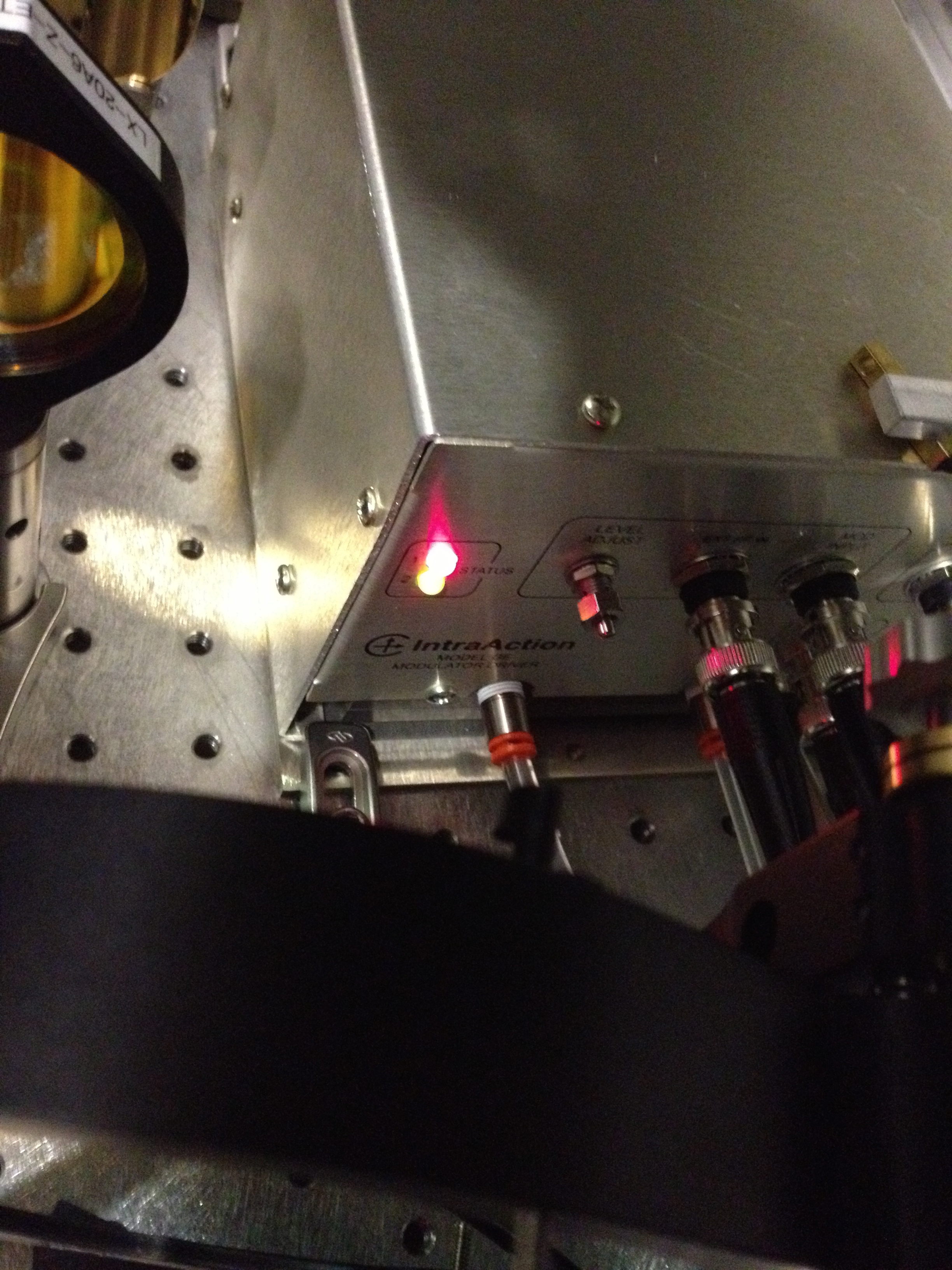
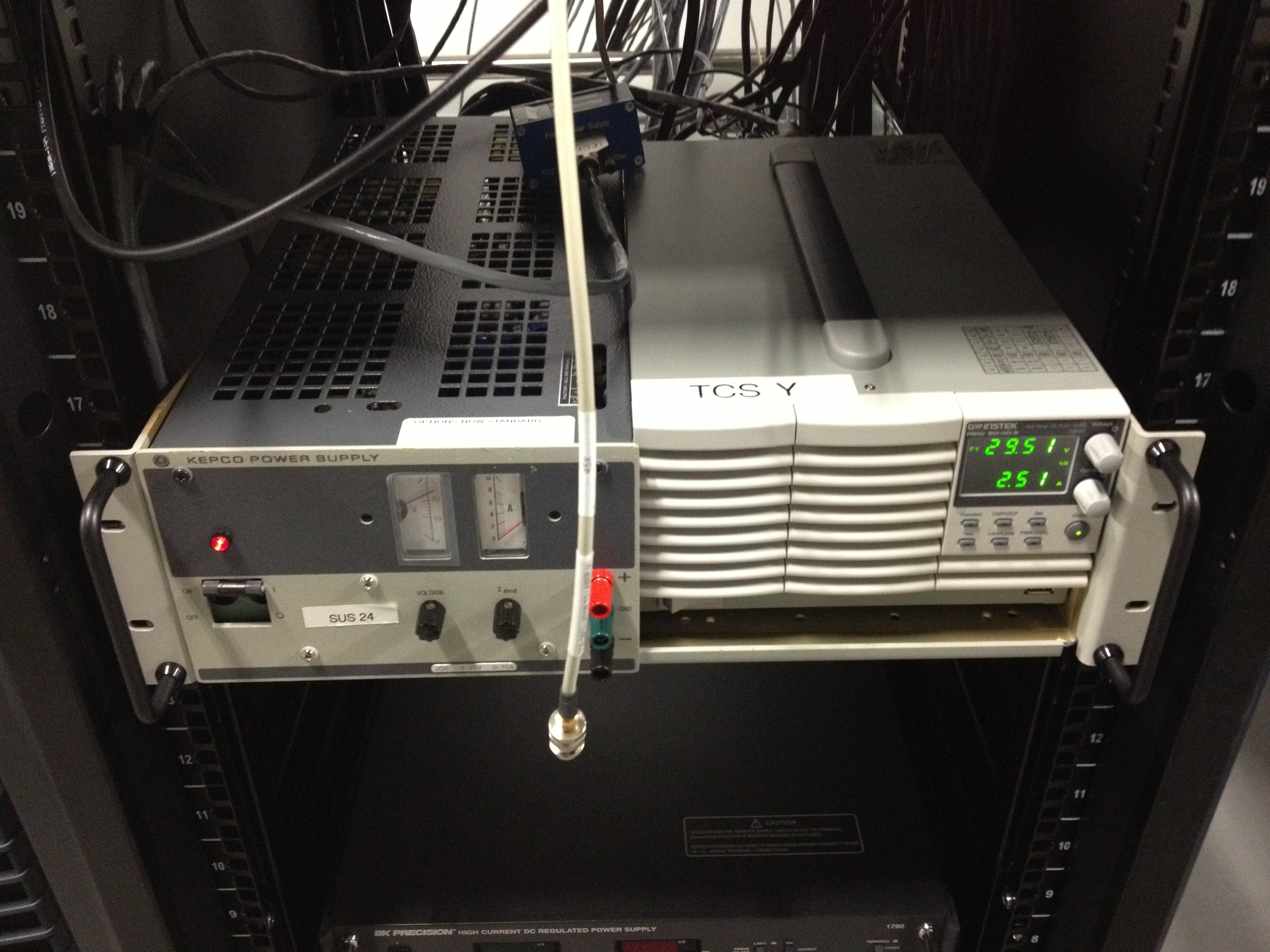
1. Only one of the Kepco power supplies is on and wired up?? and the one that was on was drawing no current (see pic Kepco power supply). This I have seen before and indicates that one of the AOM drivers has faulted. But because things look to be hooked up weird (will discuss more later) looking on the tables I see that CO2y AOM driver is fine (indicated by the two green LEDs..see pic CO2yAOM driver), but the CO2x AOM driver has faulted (top LED red...see pic CO2xAOM driver). If you want to know what these fault lights mean please go to E1500133 and look at table 1 (someone should probably print this table out and stick it on or near the AOM driver for others for future reference). Now this has been seen before at LLO and the solution is to power cycle the power supply. However doing this will make the AOM start to work, and seeing as its not known when it faulted and what static diffraction setting the driver has been set to, once the reset occurs I could alter how much power is going to the interferometer (as CO2x laser looks like its being used). So again this is something should do during maintenance period (should note what power going to optic now and so when reset see how/if it changes and alter power accordingly).
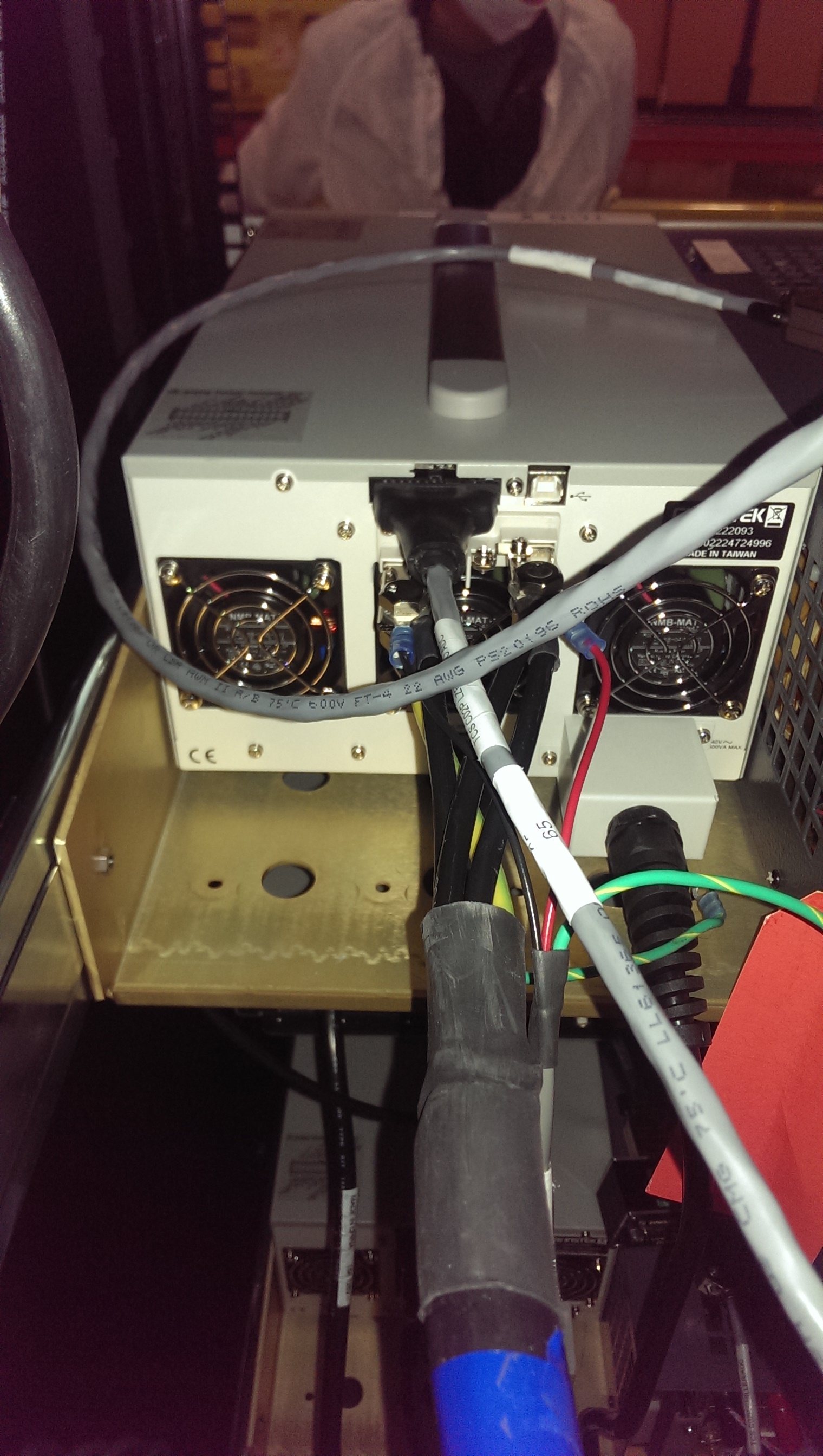
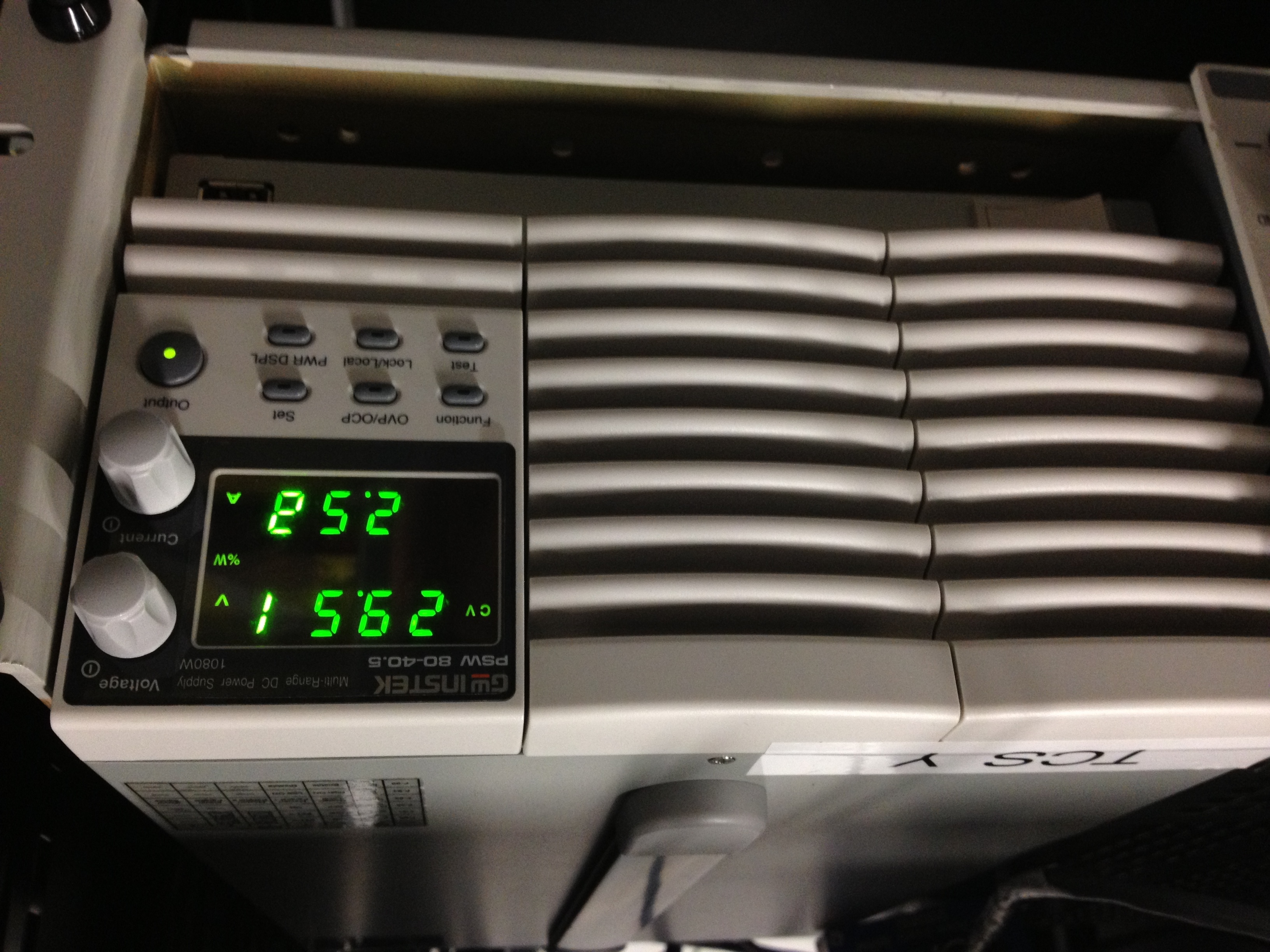
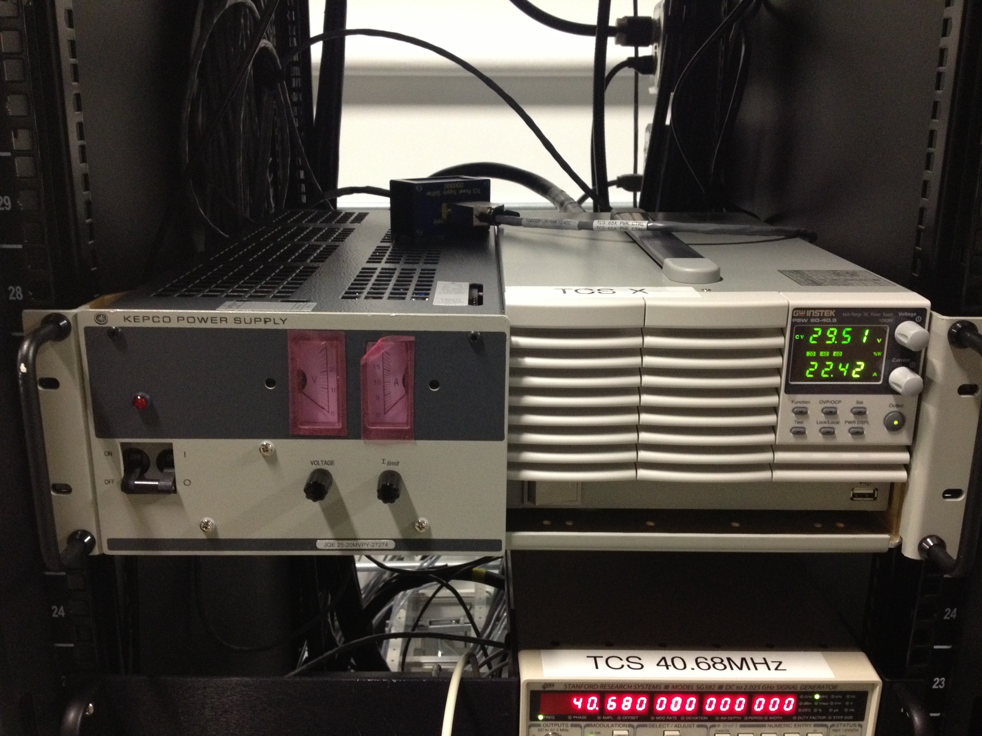
2. The CO2Y laser power supply seems to be drawing a funky amount of current. 2.5Amps actually (see pic TCSy power supply), even though the laser is off. Ive even turned the key on the controller off, so it shouldn't even be in standby mode where only draws 0.7Amps. Talking to Aidan he seems to think that maybe the AOM driver/AOM is drawing current from this supply (him telling me that made me recall we saw numbers like this back in the day when we were installing and the laser was off but we had the AOM driver on). He seemed to recall the AOM driver and CO2 laser are driven off the same supply still here at LHO (which was the original design), even though the plan was to change to having the CO2 laser and AOM driver driven off separate supplies (as has been implemented at LLO...the Kepco power supplies power the AOM drivers the other supplies power the CO2 laser only). But this doesnt seem to totally match with what Im seeing in the mechanical room.
So looking at the wiring, here is what I think is the current setup at LHO. We are in some funky mid change between having one power supply do both laser and AOM driver and having separate supplies for all. In more detail......The two shelves showing the power supplies for TCS are shown in TCSracklowershelf and TCSrackuppershelf. How it should be as per the latest plan that I know of (and is at LLO) is that the on the lower shelf should hold the power supplies that power one table (ie say Y ) and for the upper shelf the power supplies for the other table (X) with seperate supplies for the lasers and the AOM drivers. What seems to be the case is that:
*on the lower shelf we have the Instek supply (I think thats the brand name....its the the one with the digital readout reading its drawing 2.5Amps that says TCSY on top of it) powering BOTH the CO2y laser and the CO2y AOM driver (I think this because the laser is OFF, as is the controller, but the AOM driver on the Y table has not faulted and is "running".The x table AOM driver has faulted and is not "running" and 2.5amps is an approximate number that the AOM driver could be drawing).
* The Kepco power supply on the lower shelf is wired up but not drawing any current at the moemnt and thus and looks to be powering the AOM driver for the X table (why... because the x table AOM driver has faulted its not drawing any current). It should be wired to be controlling the Y table if supply in the position at..or at the very least labeled clearly as to what it is powering. Mind you I could be wrong and its powering something else
* The instek supply (the one showing the digital readout of 22.42 Amps) on the upper shelf is powering ONLY the CO2 x laser (its drawing this current as the laser is on).
*The Kepco power supply on this upper shelf is not even wired up and is thus off.
What I suggest is at some stage when have some time (maybe during maintenance period next week), is to wire the system as per the new design (and as how is at LLO). One Kepco power supply is used for the AOM driver on one table and the other Kepco power supply be wired to the AOM driver on the other table. And then just have the other power supplies individually controlling the CO2 lasers. Should then also have the power supplies for one table on one shelf and the power supplies for the other table on the other shelf.
Also when turn laser back on need to see if still only drawing half the current like Greg saw and if so investigate (probably cable connection is the problem like in the past). SO quite a few things would lile to do at next weeks maintenance period.
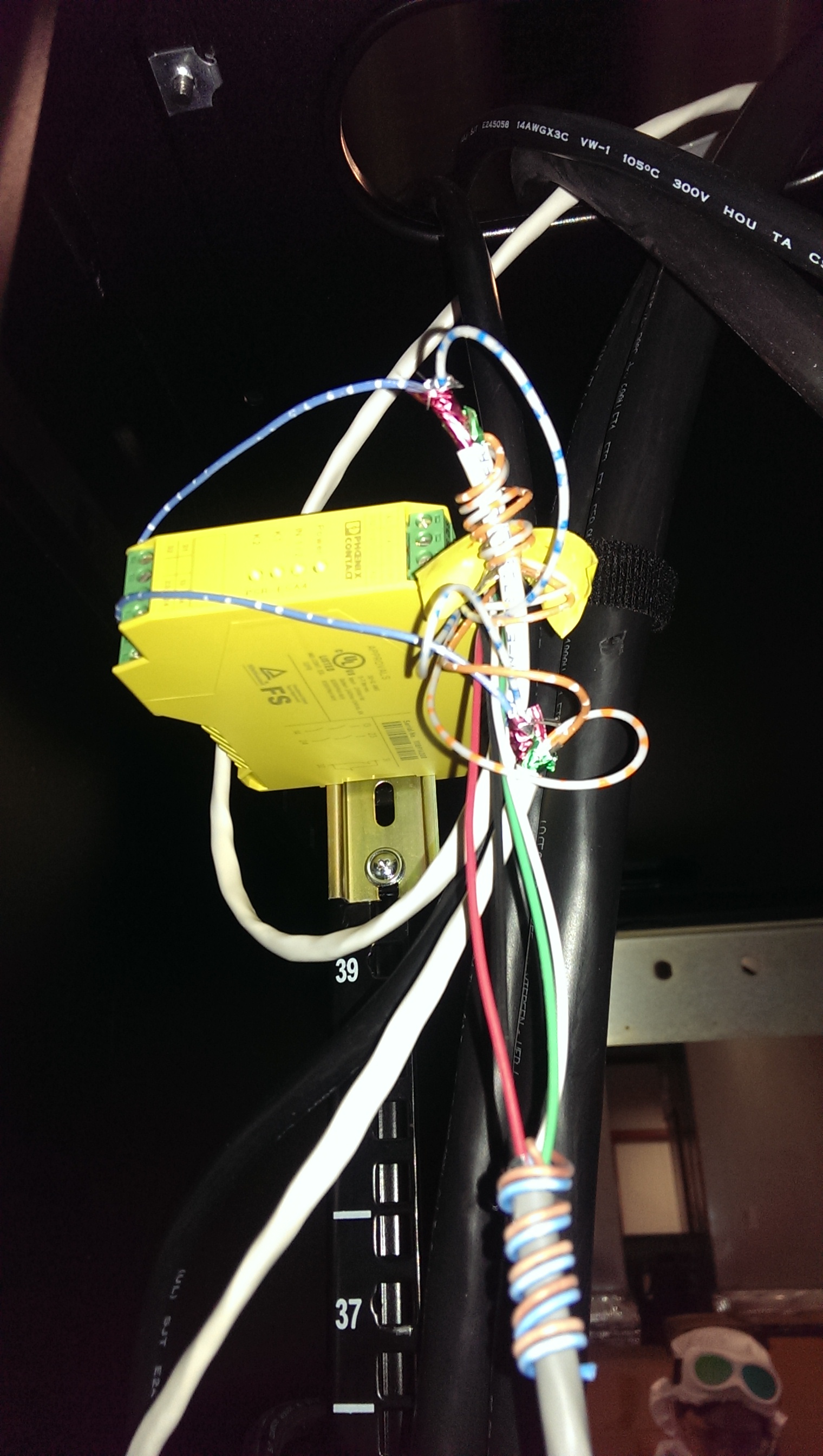
Adding a small correction to this. The AOM drivers are both plugged into their respective Instek power supplies, rather than both being powered by the Kepco supply. A Pheonix Contacts is being powered from the Kepco supply.