[Dan, Ross, Corey, Keita, Koji]
The ISC work for HAM6 was done mostly along with the procedure in this ALOG entry 17631
We first started from the steps which does not require the laser beam, and then moved on the steps with the beam.
Visual inspection of the fast shutter mirror
- The mirror on the fast shutter was checked. We confirmed that the mirror is well intact and did not show any sign of delamination.
i.e. The toaster does not seem to fly.
Beam diverter lubrication with Krytox LVP
- The two beam diverters (BDs) were removed from the table after marking their positions with dog clamps.
Corey applied Krytox along with the procedure by Matt H.
- The additional mass is added to the moving element to ensure each BD flips to the ends of the moving range.
- The BDs were returned to the HAM6 table. Their positions were aligned in the later process.
- The motion of the BDs were confirmed with EPICS I/F.
QPD cable strain relief
- QPD cable strain relieves (D1101910&D1101911) were installed to AS_C/OMCR_A/OMCR_B DCQPDs.
Now there is no chance for their ferrules to touch metal parts around there.
Transition to Laser Hazard
- The input power at this point was ~3W.
Initial alignment
- Aligned the beam on the AS_C QPD with SR2
- Aligned the beam on the OMC QPDs
- Confirmed the beam is on the WFS QPDs
OM1 mirror replacement
- The hIgh transmission (T=5%) OM1 mirror was removed from the TT suspension.
- The new OM1 mirror with T=800ppm (E1100056 Type02 s/n15) was installed.
- The old and new mirrors were supposed to have the same dimensions. However, the mirror holder faced down significantly.
This was actually the same situation as it was seen in LLO.
- I don't want to describe the detail of the TT story. In the end, the clamp units on the mirror mounts were shifted towards the face.
This let us recover the proper alignment of the OM1.
- The alignment slider values were coarsely debiased by aligning the TT suspension structure.
- All the BOSEMs indicated that the flags are too deep inside the BOSEMs. This was fixed.
- We actually debiased the suspension at the end of the procedure again.
- The AS AIR/AS_C pathes were aligned. The beam was faint and we decided to inclease the input power to the IMC up to 7W.
The beam was aligned to hit the AS_AIR periscope mirror. The AS_AIR beam on the ISCT6 table should be aligned.
- The BD for AS_AIR was aligned. The reflection of the BS was also aligned.
90:10 BS insertion
- A 90:10 BS (E1500009) was installed in the OMCR path. In order to accommodate this new optic, the steering mirror just in front of this BS
was moved back towards the OMC. We made sure the beam is hitting the OMCR periscope mirror. This changes the angle of the beam on
the ISCT6 table. Therefore, the OMCR beam on the ISCT6 table should be aligned.
- A V-beamdump is installed for the reflected beam of this BS.
- The OMCR QPD sled path was realigned.
Power budget
- The optical powers at the various places on the table were measured. Also the AS_AIR and OMCR powers on the ISCT6 were measured.
These measurements allows us to estimate the optical powers in the chamber using the ones on the ISCT6 table.
Double checking
- The optical path was traced from the septem windows to the OMC, AS_AIR, AS_WFS, OMCR paths.
- The shutter mirror was lifted manually to see if the reflected beam is still properly dumped.
- Took photos of the table for updating the table layout.
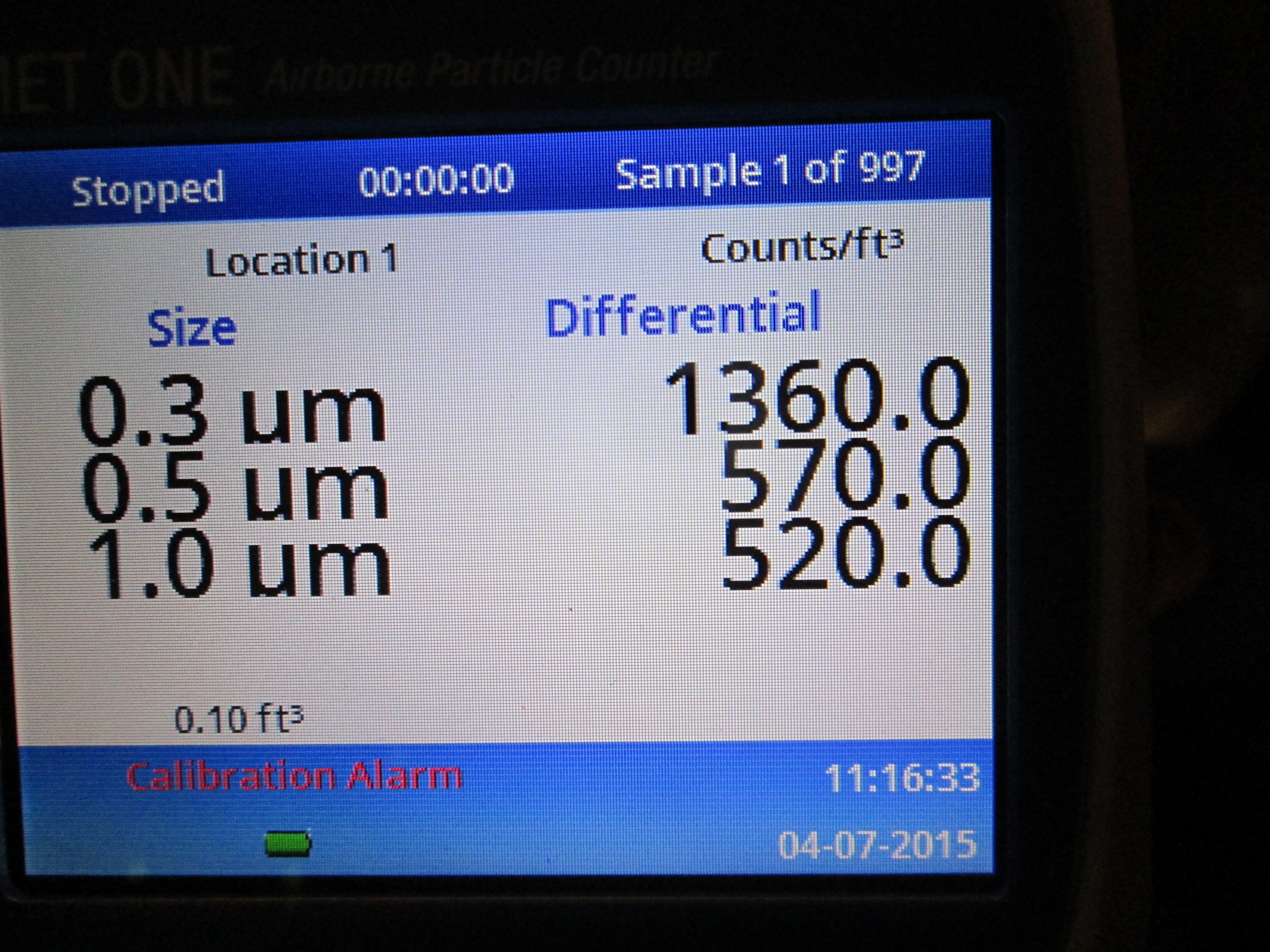
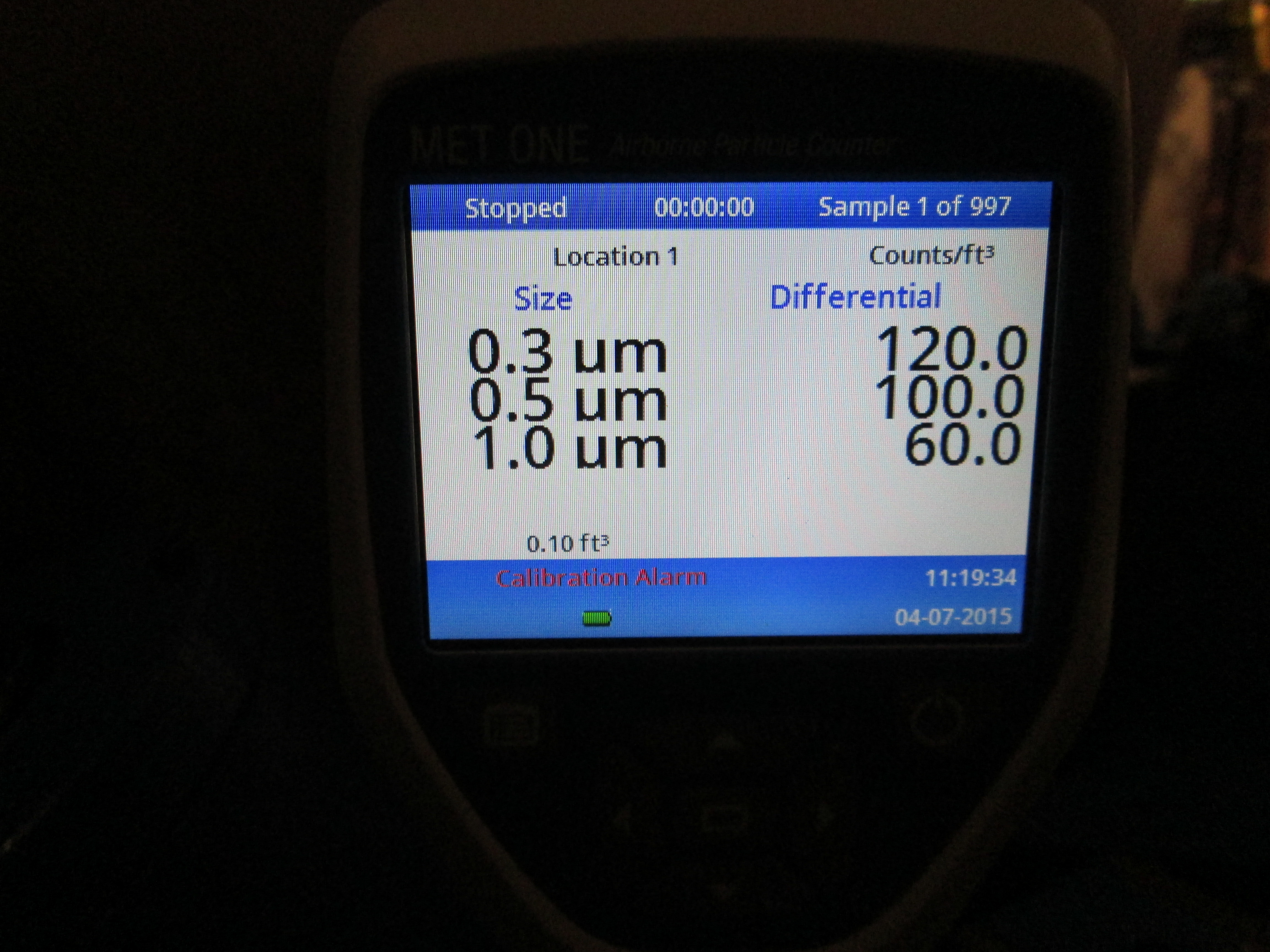
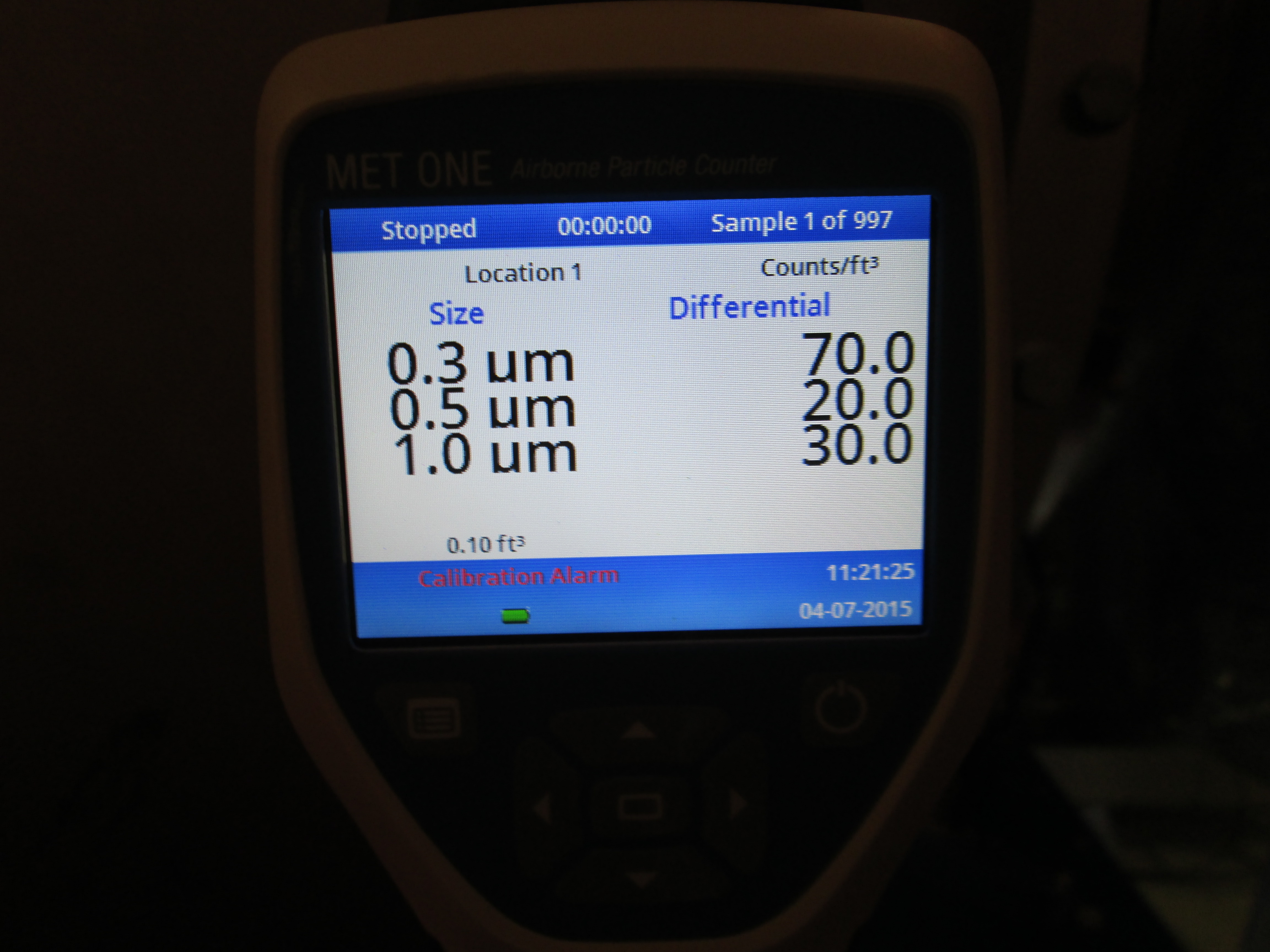
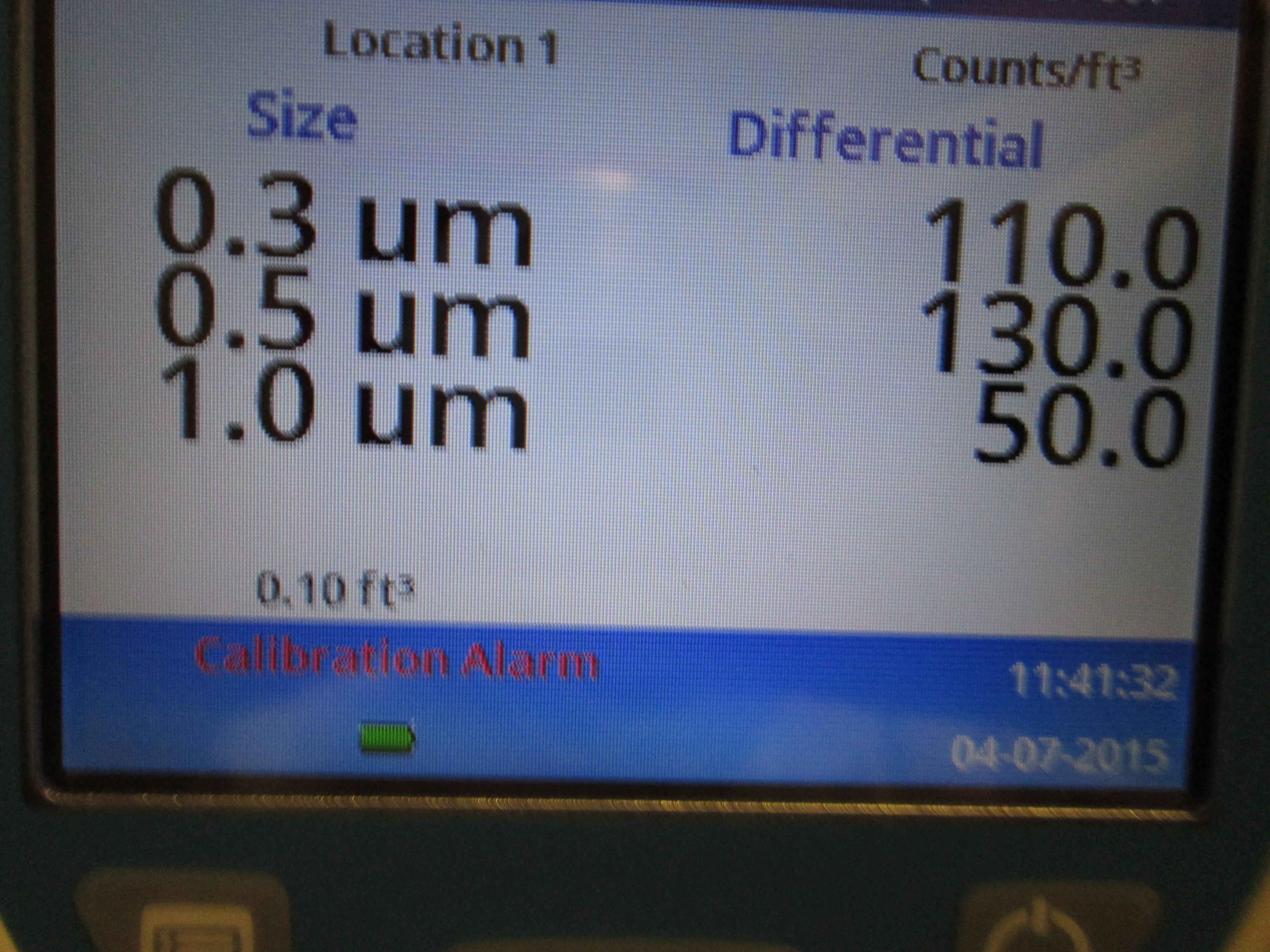
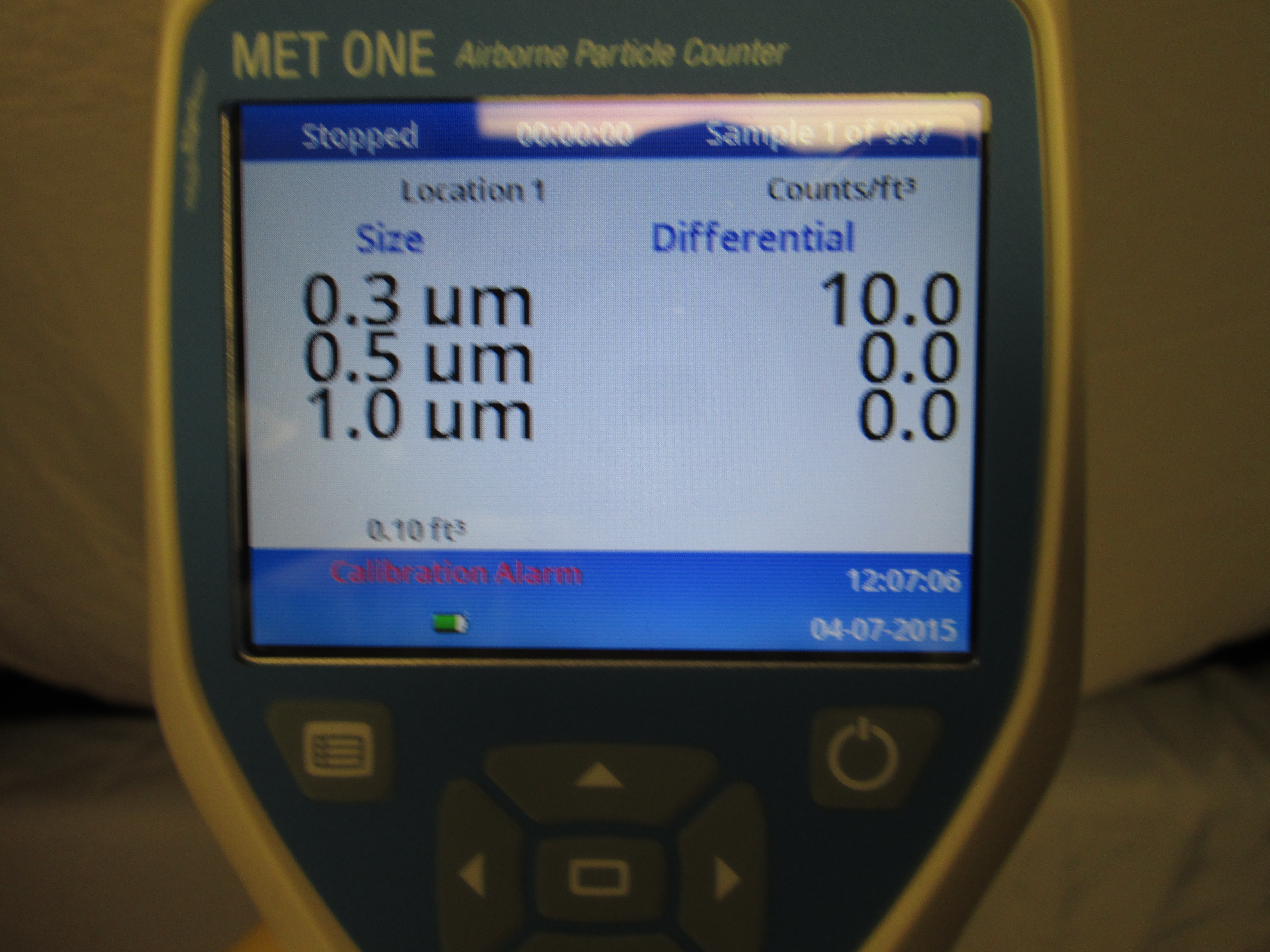
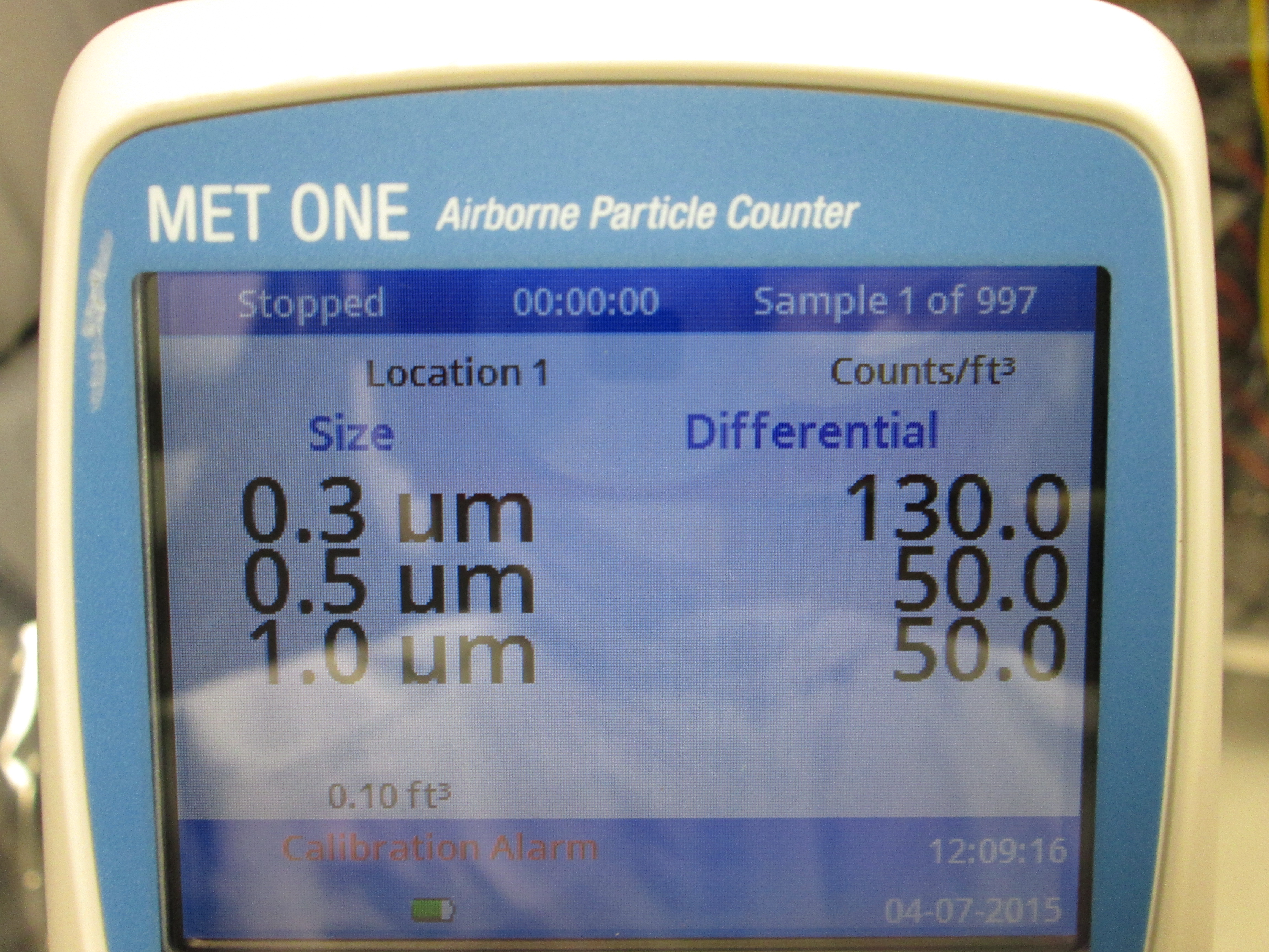
Contamination control
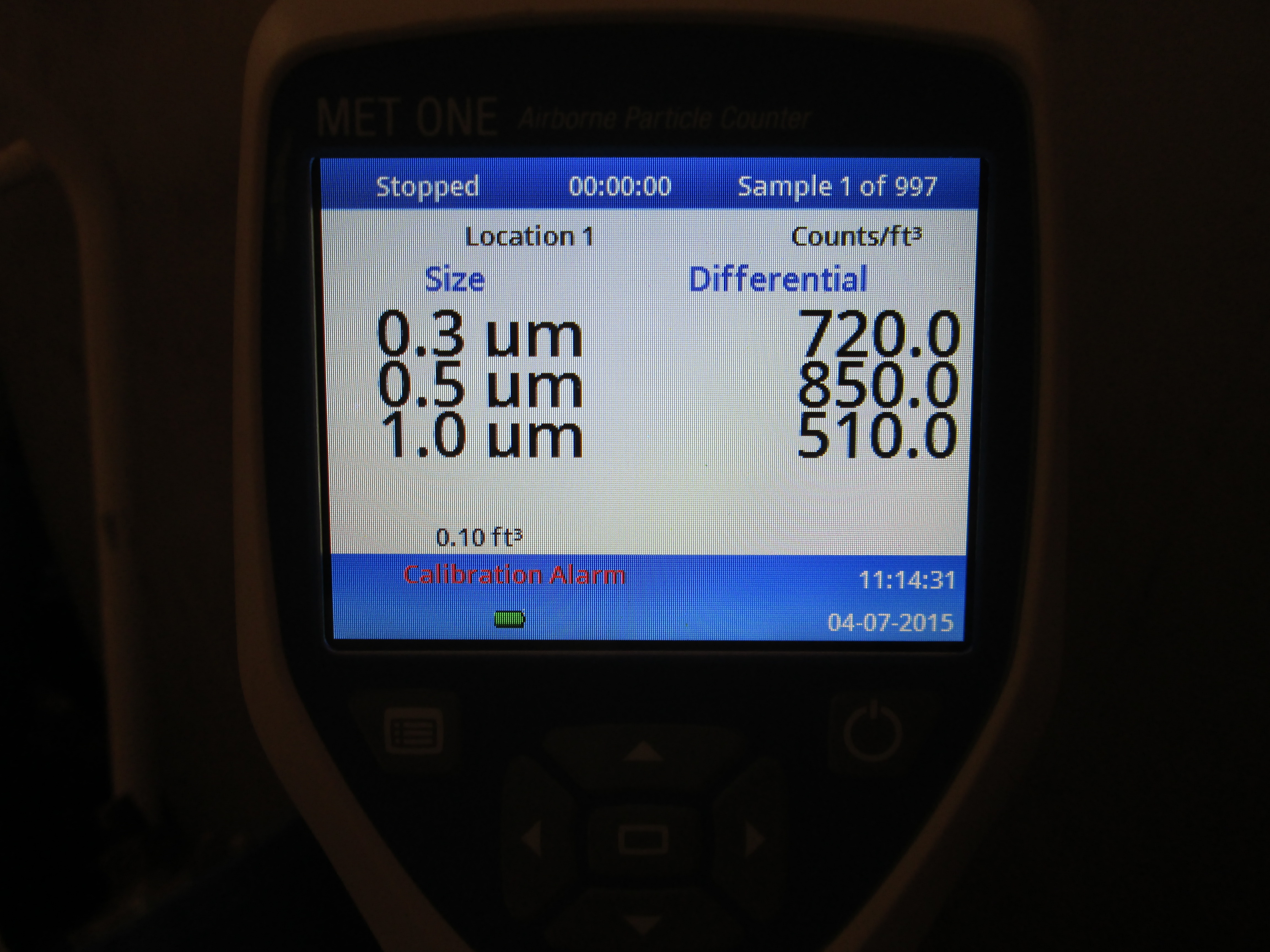
- At the end, the partice level was checked in the HEPA booth. It shows 0 counts for all particle sizes.
Still to do before closing the door
- It should be checked if the picomotors and fast shutter are still working.
- It should be checked if there is any ground shorting.
Note that BDs are shorted on the table. Also the cable harness on the OMC shorts the shields of the OMC QPD/DCPD cables at the OMC breadboard.


Regarding 90:10 BS, note that a thicker 2" Siskiyou lens holder instead of mirror holder was used, as was the case at LLO.
Since we have 36 dB less power on the ASAIR diodes, I have compensated for this in the ASAIR RF filter modules.
ASAIR_RF_90 had 18 dB of analog whitening gain. It now is maxed out at 45 dB, and there is 9 dB of gain inserted into FM8.
ASAIR_RF_45 had 6 dB of analog whitening gain. It now has 42 dB of analog whitening gain. Since we are going to remove the ND filter in front of the PD, this will have to be redone.
In both cases I also retuned the dark offsets.