jim.warner@LIGO.ORG - posted 14:47, Monday 06 April 2015 - last comment - 16:25, Monday 06 April 2015(17702)
More BSC blend filter ellipses
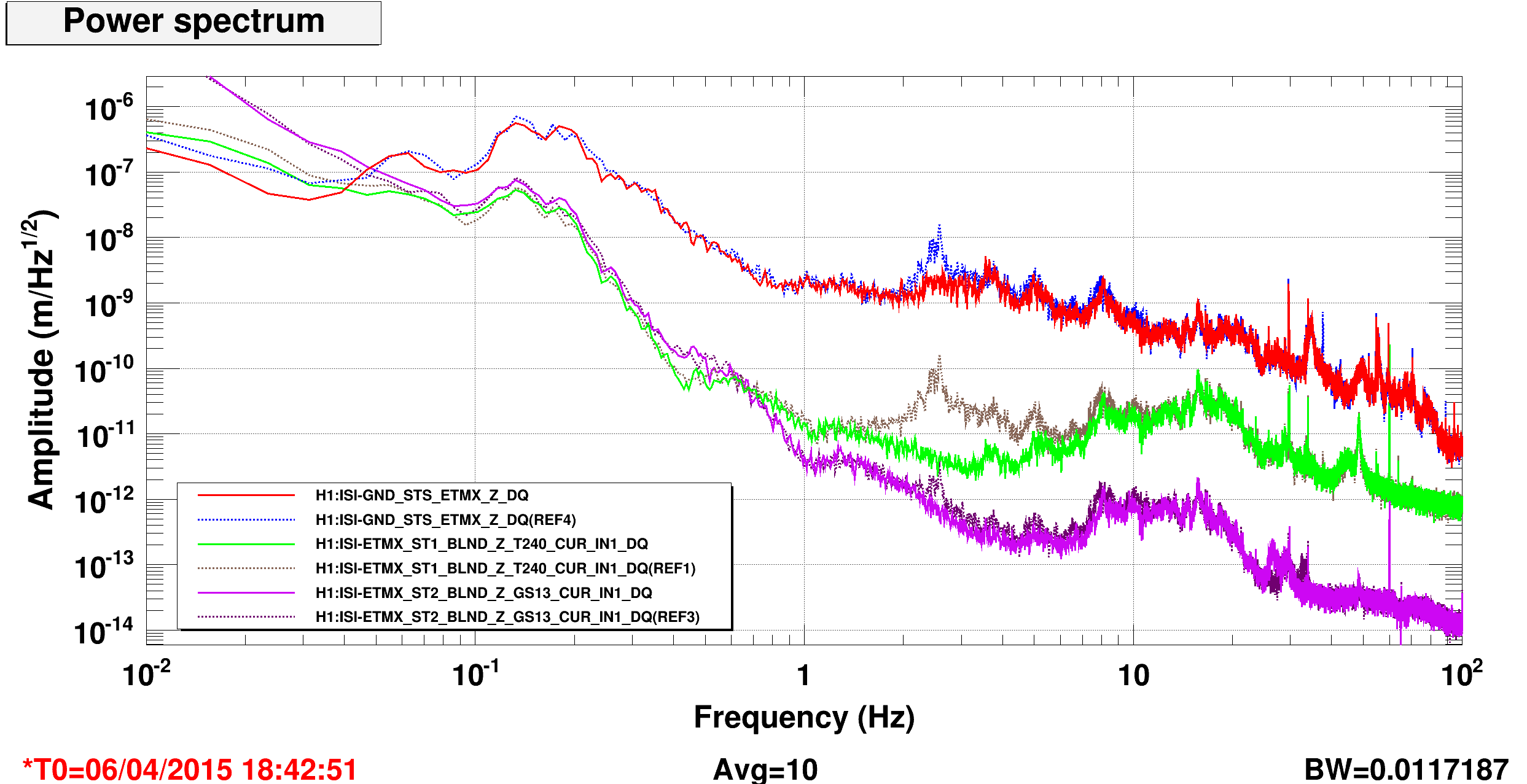
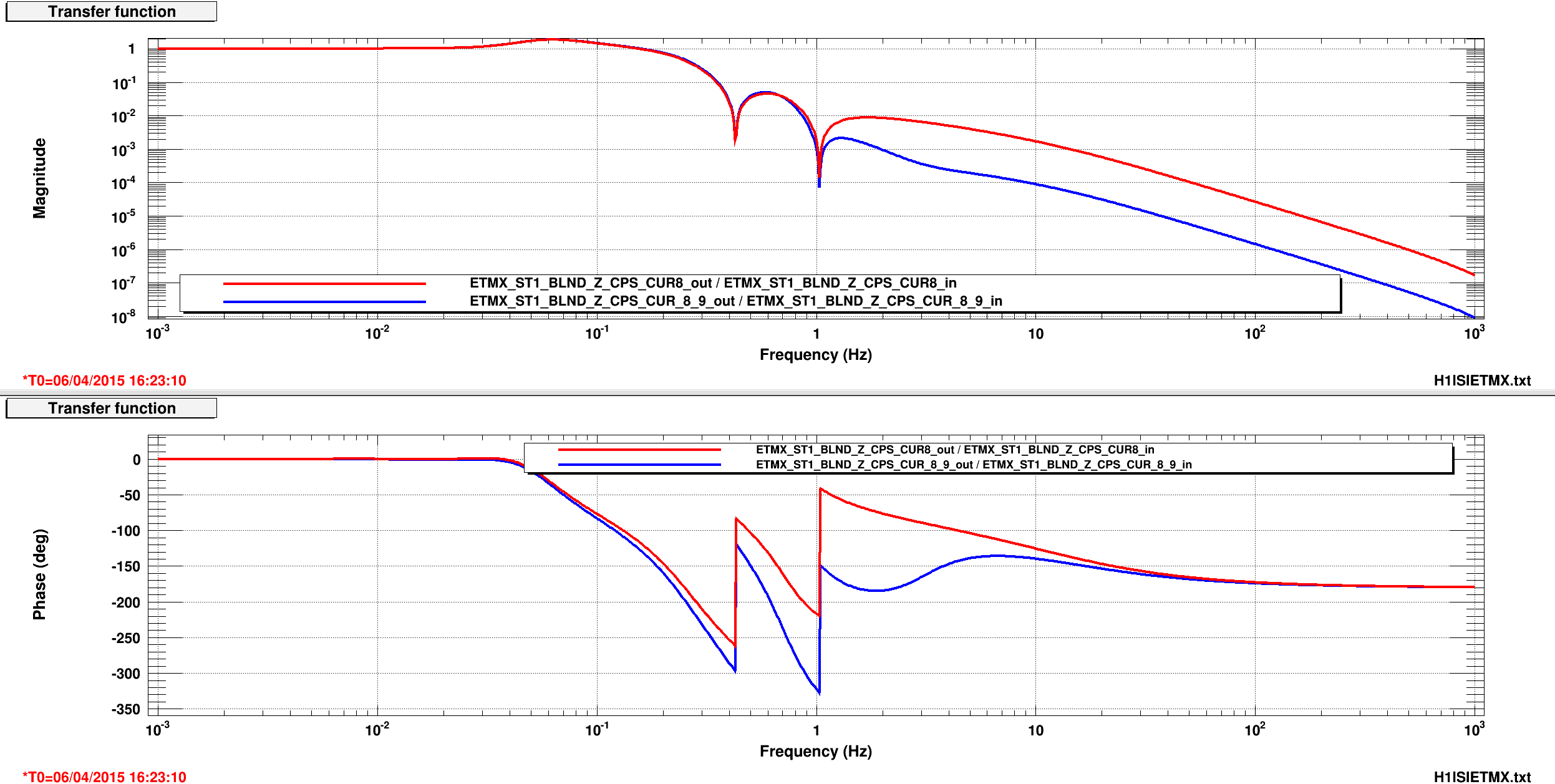
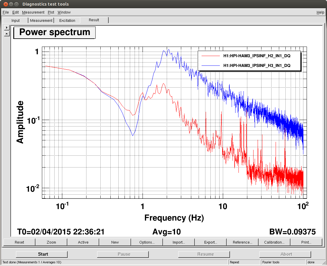
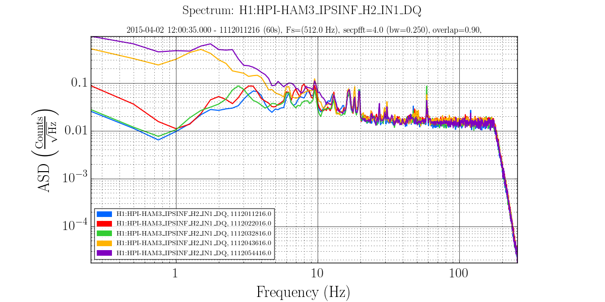
This time on St1, only in Z. Good improvement at a few hz, not as broad as the St2 improvement. First attched plot shows the improvement (mostly between 1 and 5 hz), dashed lines are off, solid are with the ellipse on, red and blue are ground, greens are St1, purples are St2. Second plot shows the change to the CPS part of the blend, red is stock, blue is with the ellipse. I am only trying Z right now because the sensor correction is offloaded to HEPI, so changing the CPS phase won't affect the SC performance. It might be possible to do something similar in X and Y, but harder, because changing the CPS plant phase will affect the sensor correction.
Images attached to this report
Comments related to this report
J. Kissel, J. Warner

One might notice that there appears to be little improvement on ST2, so one might ask "why bother?" Here's why:
On ST2, the platform was already close to being limited by sensor noise, but judging by a comparison of the shape of the ASD between ST1 and ST2, ST2 was still dominated by residual seismic noise from ST1 at these frequencies. The improvement of a factor of 50 at 3 [Hz] pushes the residual ST1 motion *well* below the sensor noise floor. Even though this doesn't improve the displacement of ST2 by much, it should improve the stationarity of ST2 significantly, given that sensor noise is stationary and residual ST1 motion from ground is not.

Another victory for Jim!


