Koji, Sheila, Dan, Evan
Summary
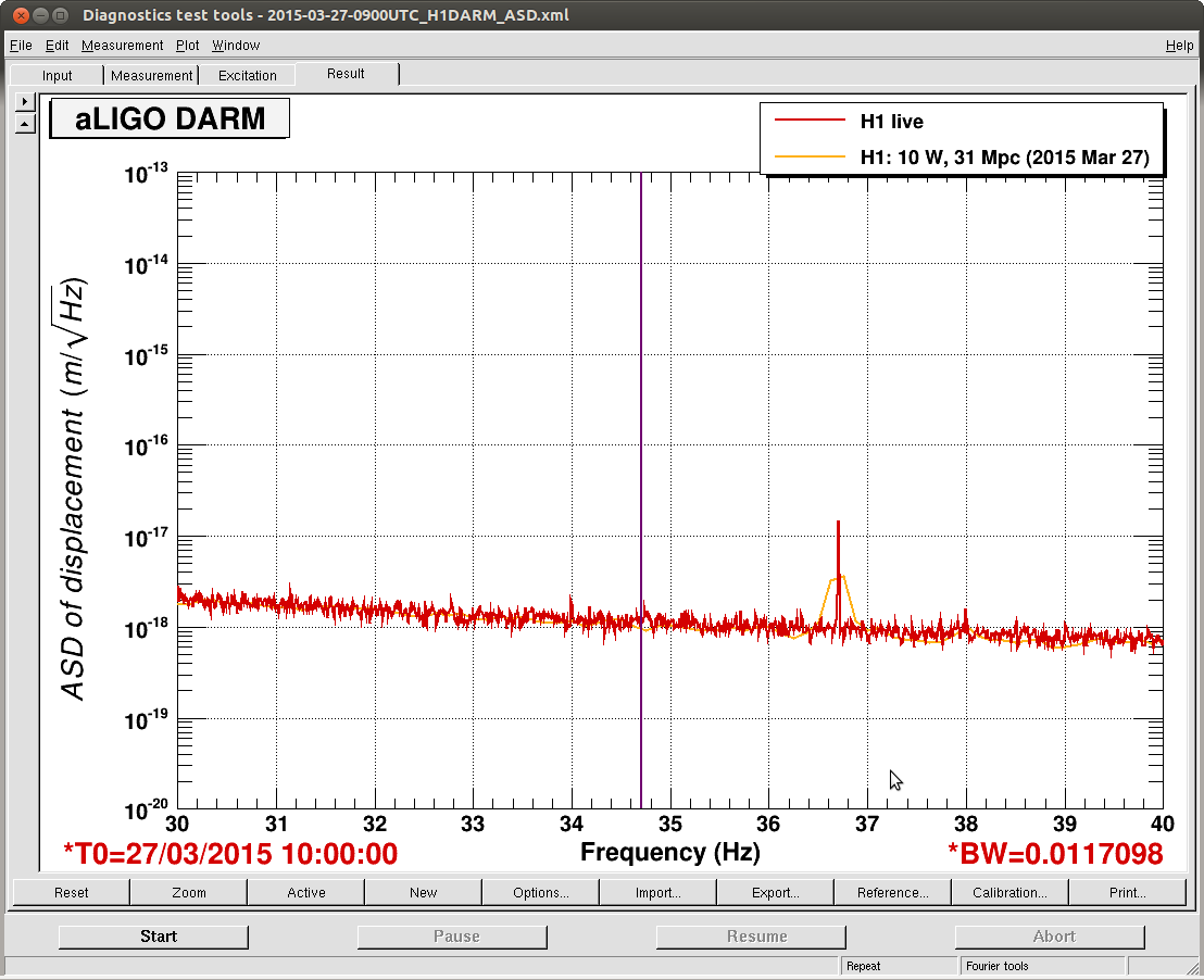
Noise coupling measurements for MICH, SRCL, PRCL, intensity, and frequency have been taken.
We also tried a few small noise-hunting activities.
Details
Coupling measurements
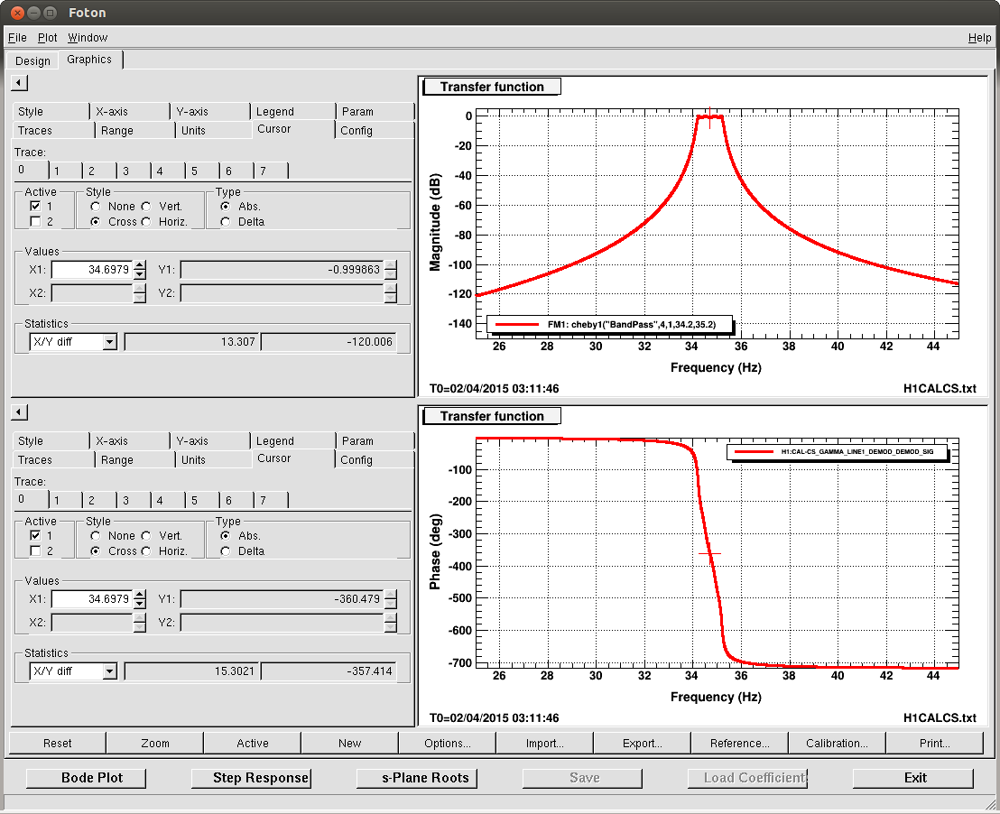
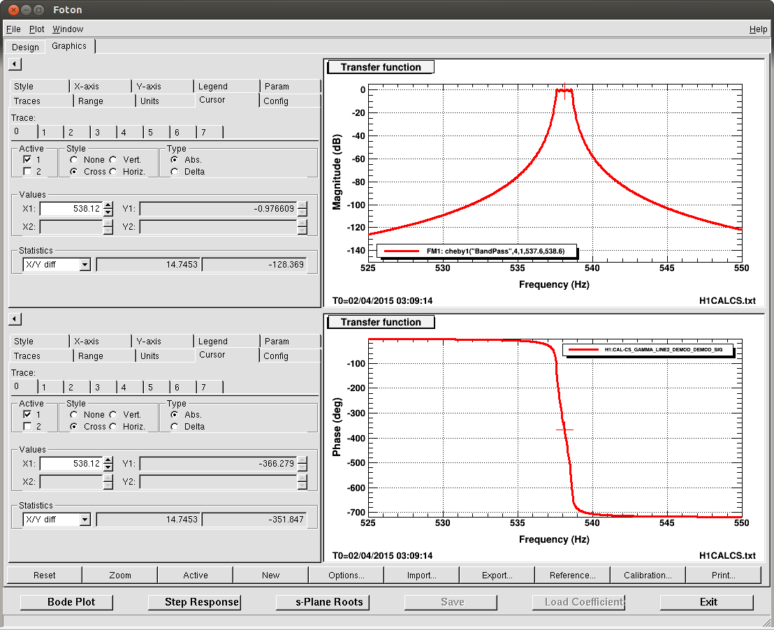
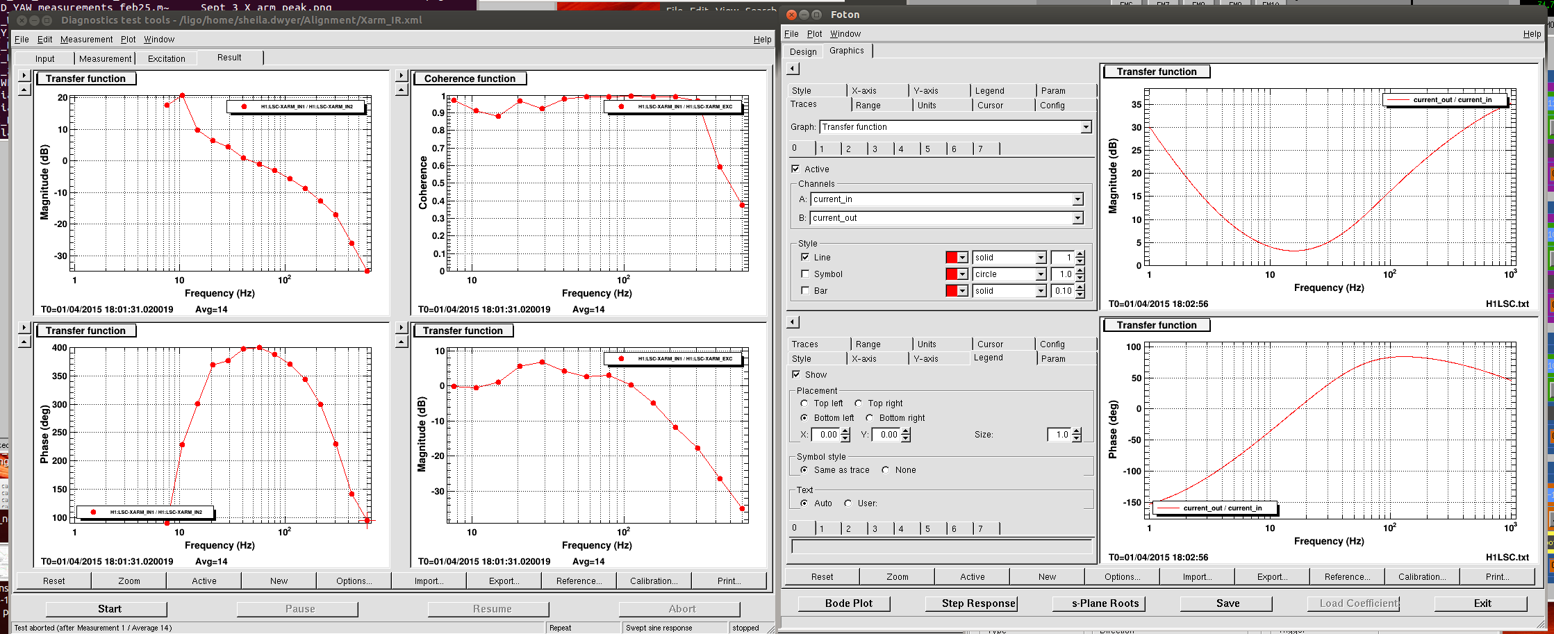
For PRCL, MICH, and SRCL, we excited each dof with a swept sine and then recorded the transfer function from the error signal (IN1) to the DARM channel. MICH was already done previously.
For intensity, we did the same as described earlier.
For frequency, we used the same DAC channel (LSC-EXTRA_AO_2) to drive the common-mode board excitation point with a few millivolts of swept sine. Then we recorded the transfer function from REFL_A_9I (which is out of loop) to the DARM channel.
The dtt files are attached. More analysis to follow.
Other
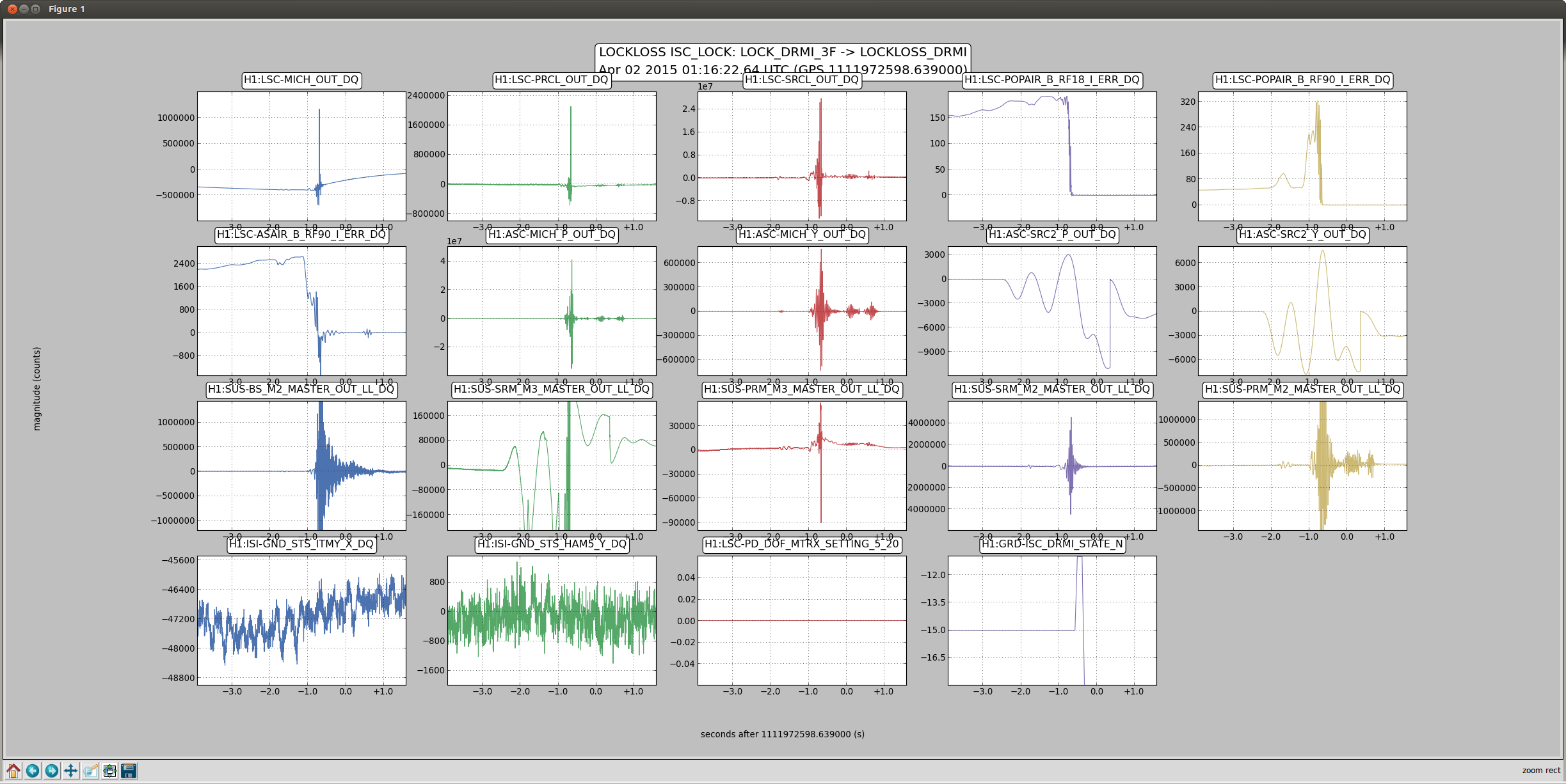
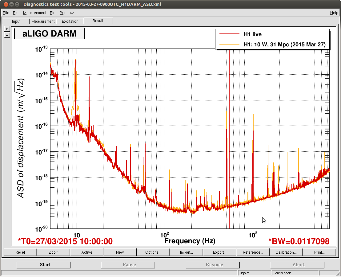
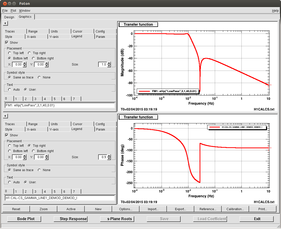
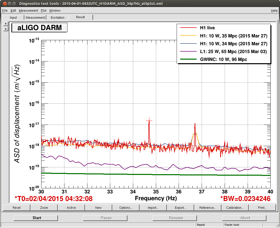
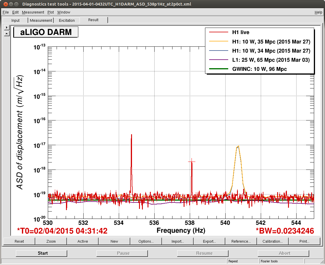
Koji and I saw that ASC-MICH_P had significant cohrence with the DARM spectrum between 20 and 40 Hz. We took an OLTF and found that the UGF was 2 Hz with 60° of phase. We installed an elliptic LPF at 20 Hz, which removed most of this coherence (see attached). Correspondingly, the DARM spectrum dropped by a factor of 1.5 or so around 30 Hz.
We then tried to tune the bias of the EX ESD to see if we could improve the DARM spectrum. We could not find a sharp optimum; rather, anything from −190 V to 0 V seemed to be OK.
Koji then suggested trying to excite a scattering shelf in DARM by driving the OMC suspension. We drove the suspension longitudinally, transversely, and then vertically by a few microns at 0.15 Hz, but we found we could not make anything appear in the DARM spectrum.
Twice today the high voltage for the OMC PZT tripped, requriring the power supply to be reset by hand. The voltage is set at 100 V and the current limit is 2 mA. The quiescent draw is 0.8 mA.


DARM OLTF attached.