jeffrey.kissel@LIGO.ORG - posted 22:20, Tuesday 31 March 2015 (17599)
H1SUSITM Models Modified Again Because DARM_CTRL Wasn't Sent to ITMs
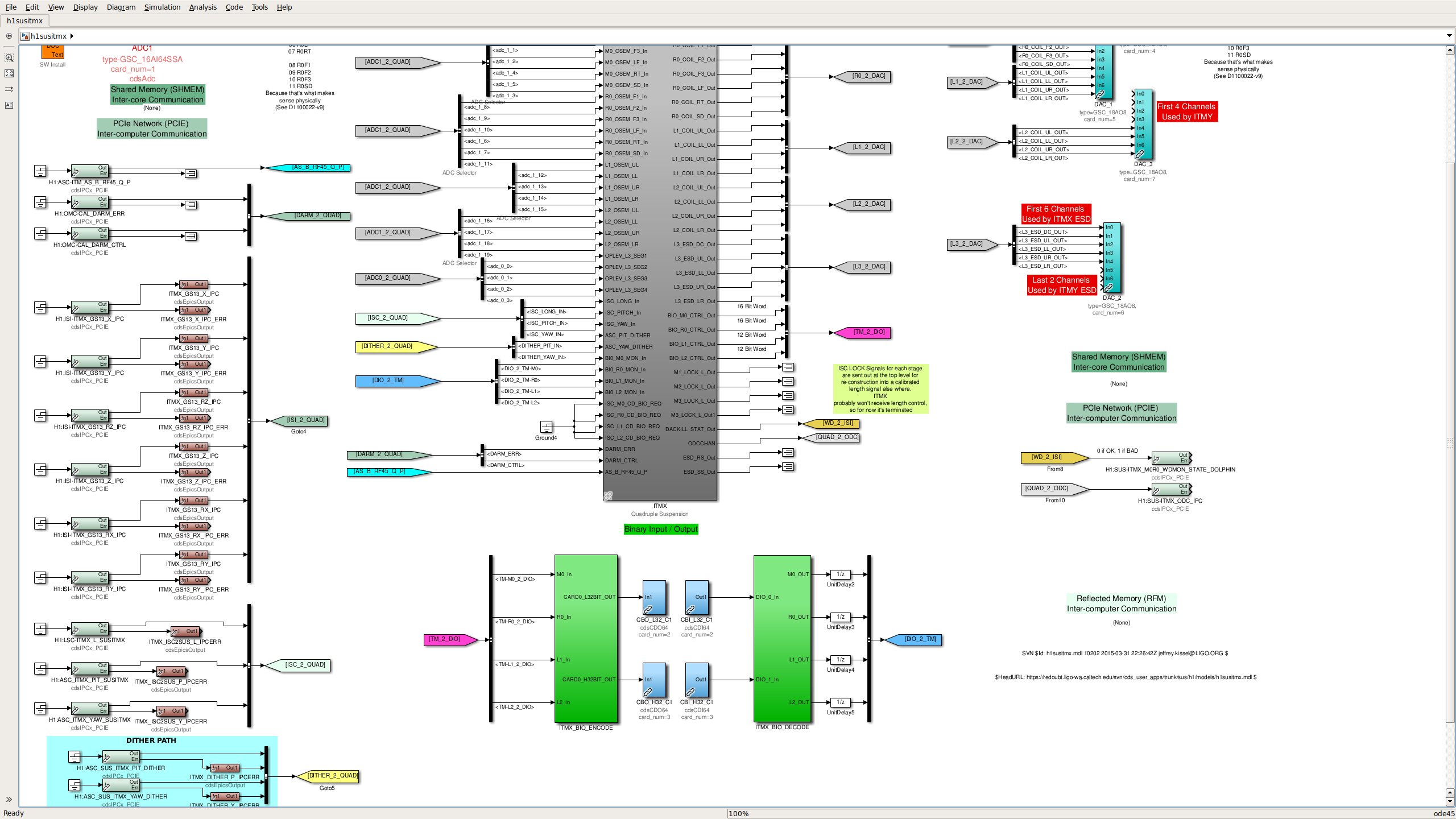
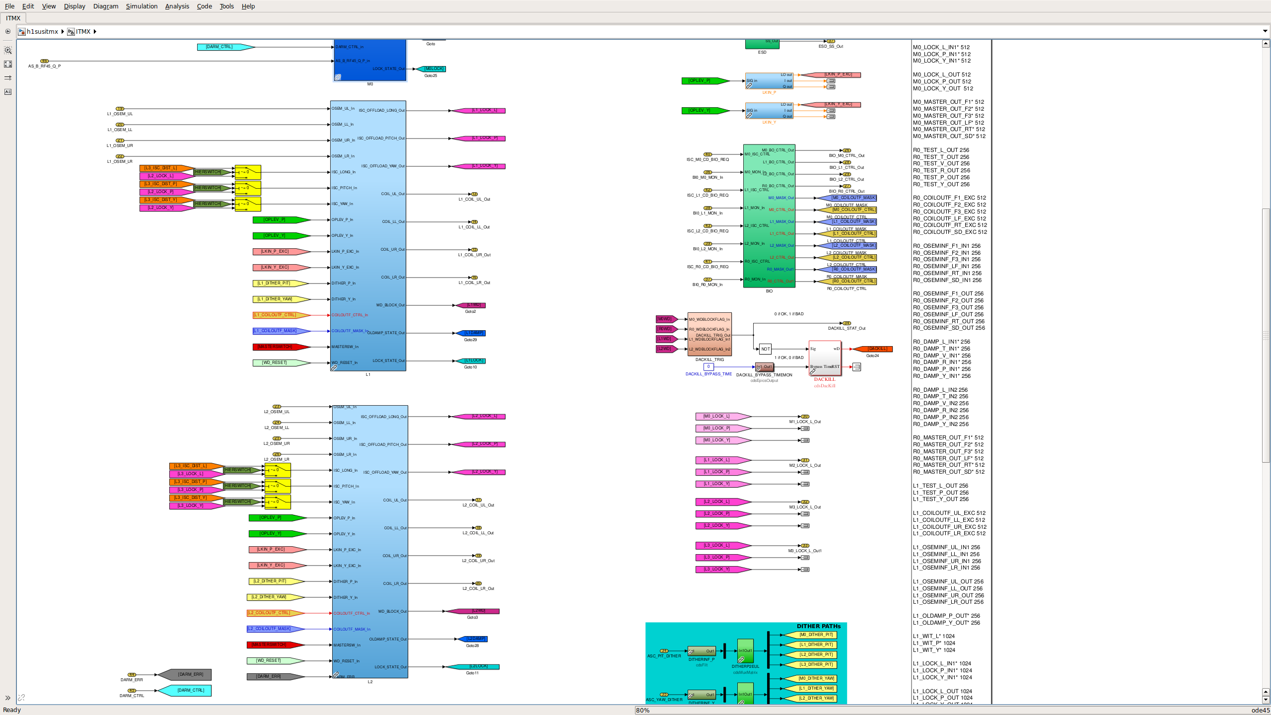
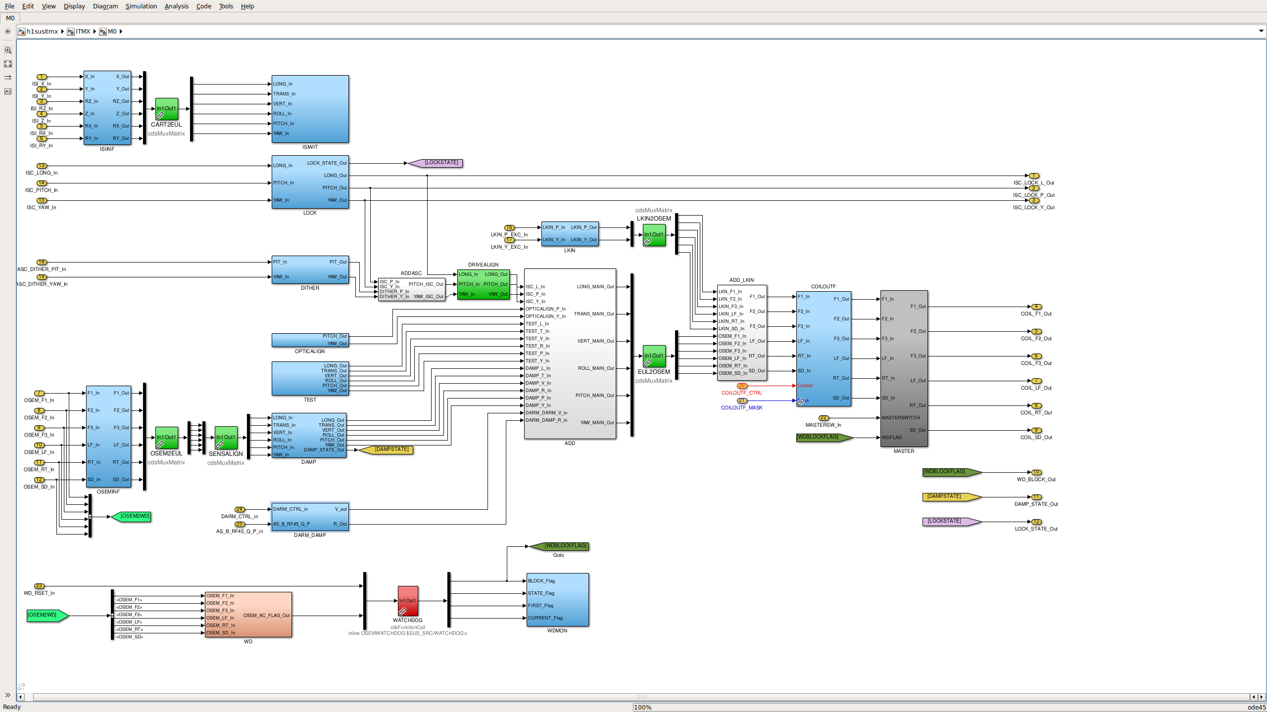
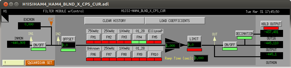
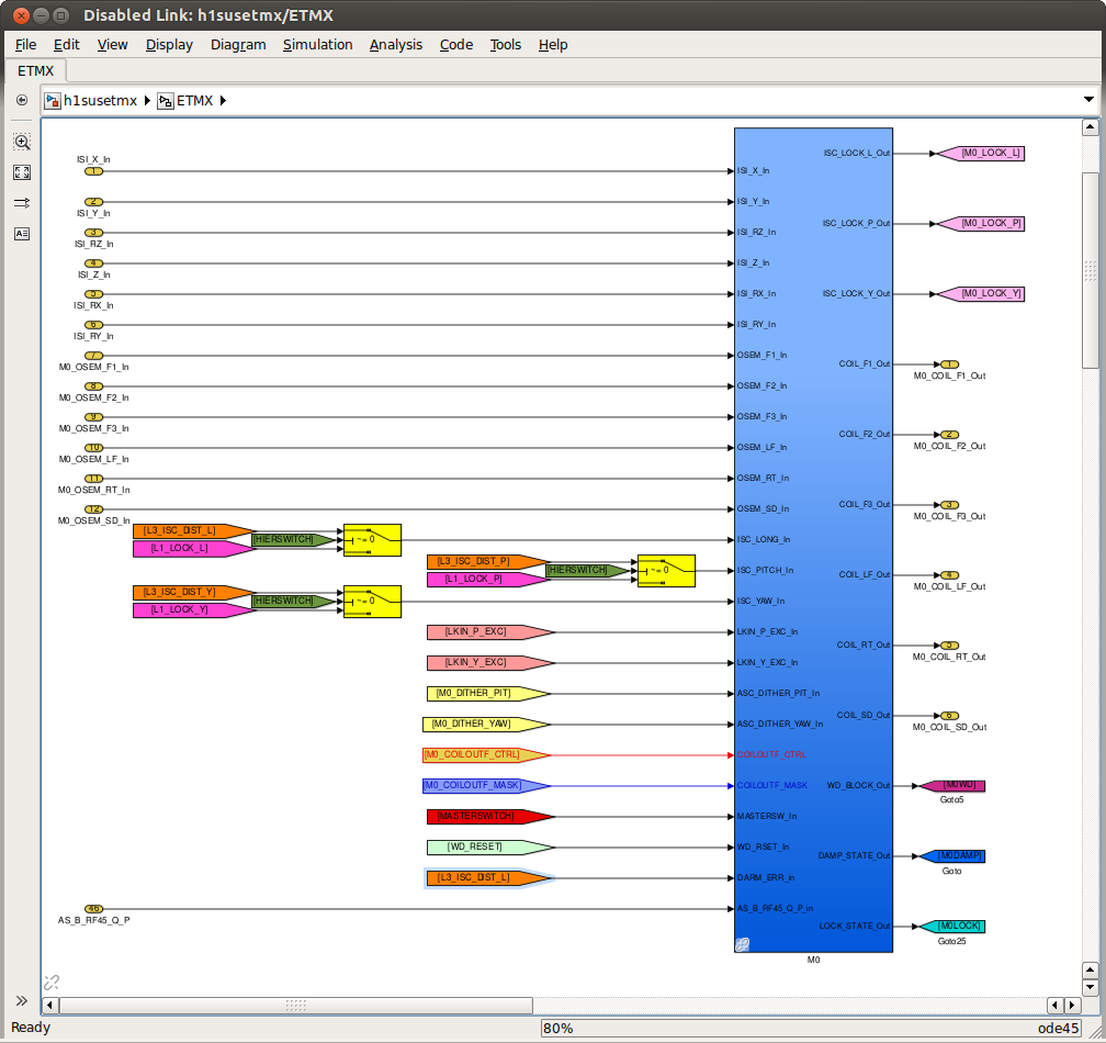
J. Kissel, E. Hall, S. Dwyer

After getting back to a reasonable DARM spectrum, we began experimenting with the new DARM_CTRL damped 9 [Hz] highest vertical mode. We quickly discovered that the change made for the ITMs won't work, because the single pipe in which ISC control comes into the suspension -- which is what we'd picked off the control point from to feed to the top mass -- can no longer contain DARM signals after we split / redistributed the LSC and OMC front-end code (i.e. there are no DARM to ITM output matrix elements in the LSC control).

Evan hacked around the problem for tonight by using the input matrix to pipe DARM_ERR straight through the YARM bank, and out to the ITMs.

However, for a more permanent solution, I've modified the ITM models (again) to include a new PCIe receiver of the H1:OMC-CAL_DARM_CTRL IPC channel (already being broadcast in the corner for the CAL-CS calibration of DELTA L EXTERNAL), which is now piped separately from DARM_ERR into the main QUAD block, and fed to the top mass for bounce damping.

The model changes for h1susitmx and h1susitmy are complete, I've confirmed that they can compile, and I've committed the changes to the userapps repo. The attached screen shots show the various portions of the model that were changed.

We (either Stuart or myself) will install and restart the front-end process in the morning.
Images attached to this report