SudarshanK, RickS
Yesterday, we adjusted the transmitter module optical layout to address the s-pol light downstream of the AOM (see notes appended below).
We then calibrated the system using Working Standard WS1. The details are in LIGO-T1500129.
The calibration of the TxPD output (H1:CAL-PCALX_TX_PD) is 8.517e-13 *1/f^2 (m/V).
The calibration of the RxPD output (H1:CAL-PCALX_RX_PD) is 6.799e-13 *1/f^2 (m/V).
Notes:
LHO Xend calibration
As found:
With servo output railed at ~1.5V
Total power downstream of AOM 1.37 mW
Diffracted power 1.09 W
80% Diffraction efficiency
OFS PD 1.32 mW; -9.0 V with NE01A-B filter
TxPD 6.64 mW; 2.72 V without filter
Beam seemed to be slightly clipping the transducer in the AOM
Moved the beam away from the transducer approx 1/2 turn on 4 axis mount
Now (without the polarizer)
Total power 1.55 W
diffracted poer 1.14W
75% efficiency
Moved wedge about one inch farther downstream to decrease incidence angle
Found that wedge roll angle was not well set. OFS PD too high.
Used IRIS set right in front of wedge, then adjusted vertically so iris is centered on input beam.
Then, used iris in Tx and OFS beams to adjust roll angle of wedge such that both beams are level. Note that one needs to adjust the pitch angle of the wedge for the Tx beam after making a roll angle adjustment.
After centering beams on PDs, then installing lens in OFS PD path and recentering.
Installed NE06A-B on OFS PD. 6.12 mW on OFS PD.Output was -14 V. With an additional NE01A-B we have -10.8V
Tx PD (without any filters) 12.3 mW on Tx PD. 5.1 V
Installed PBS downstream of AOM and rotated in yaw to minimize reflected light with AOM drive switched off. ~4 mW
With AOM drive on at max level 23 mW.
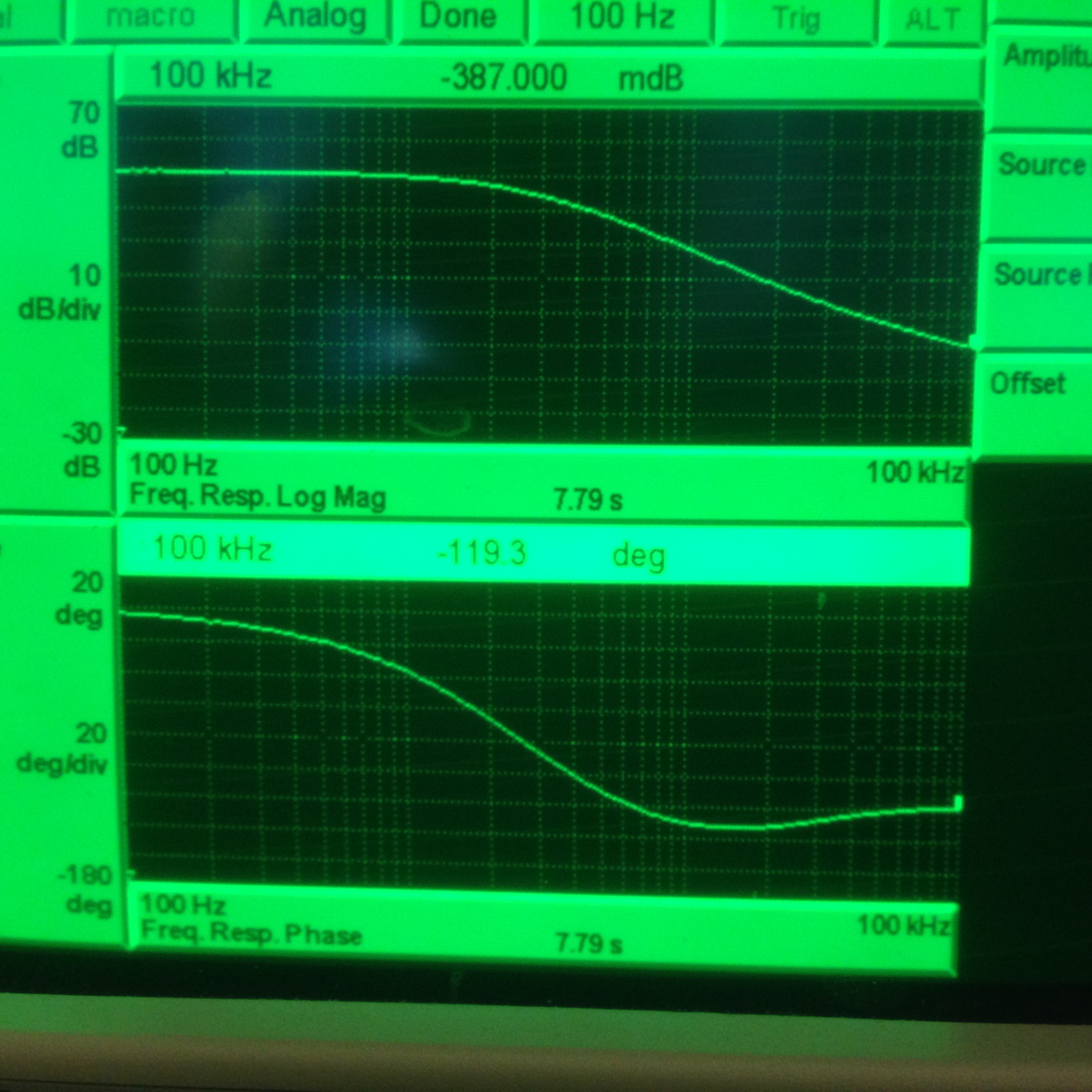
Measured OLTF (see attached photo). UGF 100 kHz with gain set to 37 dB. Phase margin 61 deg.