Evan, Kiwamu, Sheila, Dan, Lisa
Summary
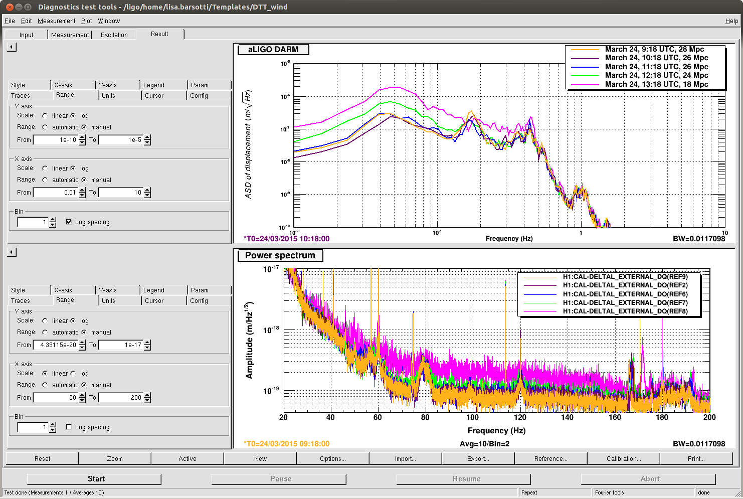
We still haven't quite finished our list of "low hanging fruits", but we are getting close. The OMC is not shaking anymore after engaging the DARM boost and reducing the RIN in transmission of the OMC by nearly a factor of 10. Also, we switched the vertex control from POP to POPAIR, which has ~5 times more light, and in doing so we reduced the noise coupling from MICH to DARM. We could reach ~ 28 Mpc again without engaging the MICH feed-forward.
Sadly, we don't have any improvement in Mpc units because a few "technical problems" slowed us down, and we didn't have a chance to finish the coil driver transitions to low noise, improve the vertex length DOF loop cut-offs, and tune the MICH/SRCL feed-forward subtraction while on POPAIR.
In particular, a typo in the ISC_LOCK Guardian (switching of a filter in the "DAMP_M0" filter bank, instead of "DARM_DAMP_MO") badly tripped ETMY (thanks to Jeff who helped us recovering by phone), and caused both roll and bounce mode to run up insanely, and we can't lock. Our damping techniques with ifo unlocked are very (very) slow, so we are giving up.
Also, the transition to ETMY with low noise ESD worked well once today, but later attempts failed (not totally clear why, the only known difference in later attempts is that we engaged the DARM boost before making the transition).
The full list of things we did/tried is below.
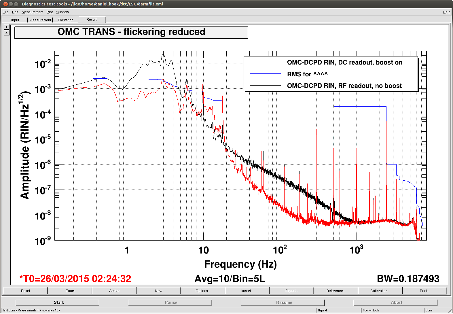
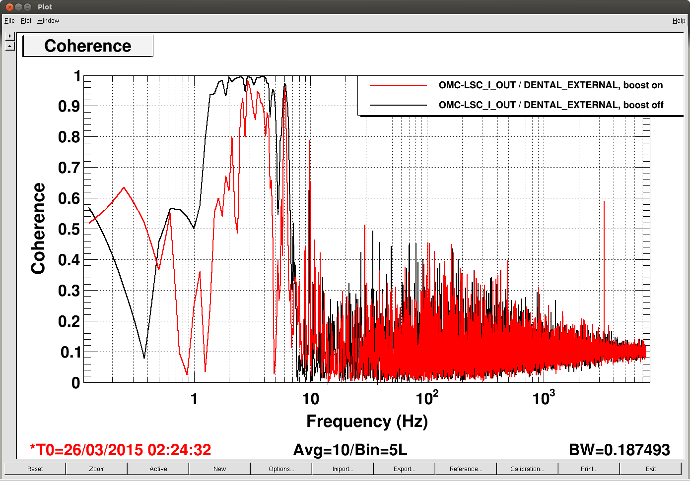
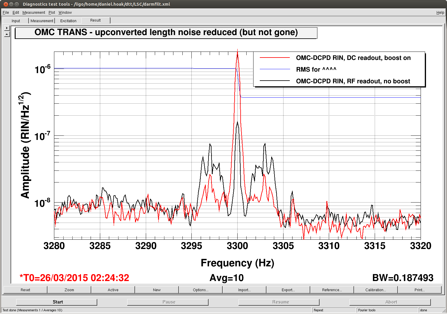
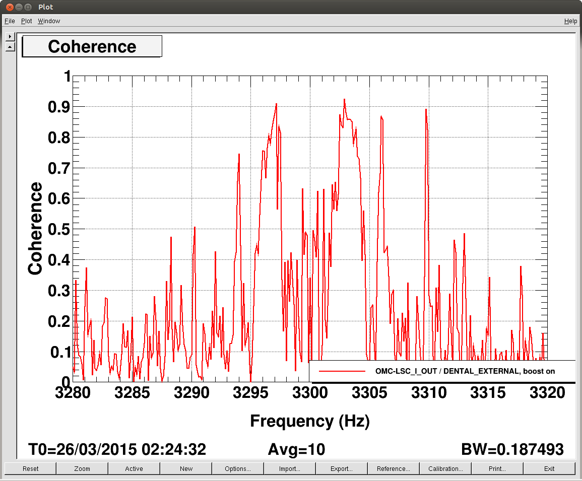
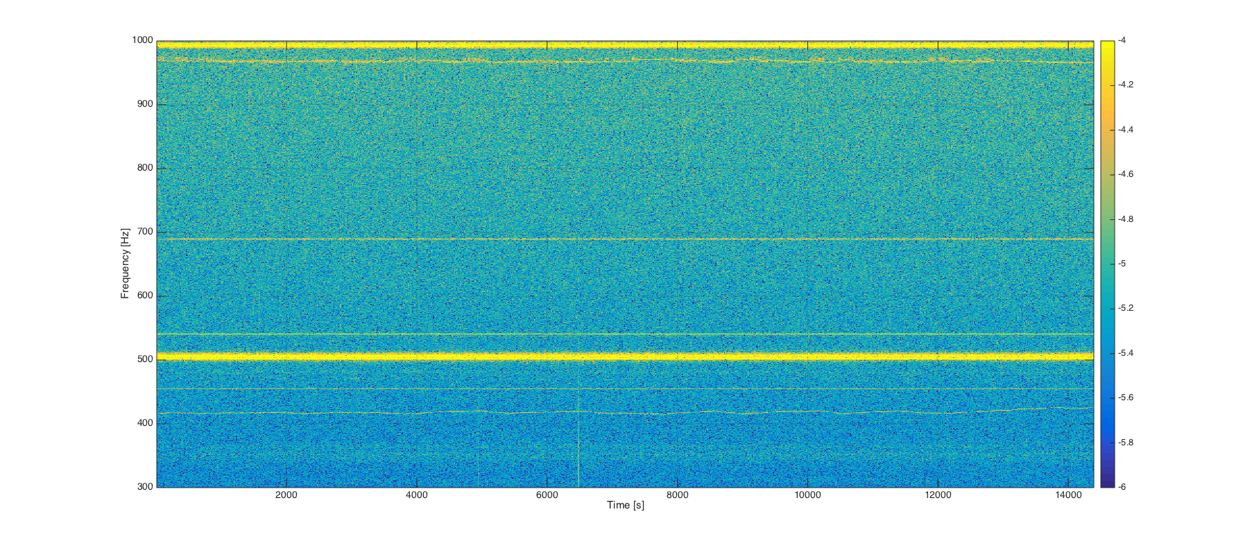
Fixed the "shaking" OMC (in the Guardian)
We reduced the DARM motion between 1 and 6 Hz, as Dan reported here, and now the OMC is happy (and we are happy with him).
Transitioned to POPAIR (in the Guardian)
POPAIR has ~5 times more light than POP, so we decided to transition from the in vac diode to the in air one, to reduce the noise coupling of the vertex length DOF to DARM. Indeed, we could reach the same sensitivity as the other day (~28 Mpc) without any MICH feed-forward.
Close ALS shutters on ISCTEX/EY (in the Guardian)
Not clear improvement, but this is the beginning of the "closing beam diverter/shutter" campaign.
Test of SRCL cut-off (not in the Guardian yet)
The SRCL loop had 60 degrees of phase at 30 Hz, and a very modest cut off filter. We tested a more aggressive cut-off, which removed all the coherence we see between DARM and SRCL above 100 Hz. We tested this filter only once, so we are not including it yet in the locking sequence.
Test of BS coil driver switch in DRMI (not in the Guardian yet)
Kiwamu and Evan imported and adapted the script that Den wrote to do the BS coil driver switching one by one. It was tested in DRMI - 1f, and it worked. We haven't tested it in full lock yet.