jeffrey.kissel@LIGO.ORG - posted 10:09, Tuesday 03 March 2015 - last comment - 15:10, Tuesday 03 March 2015(17037)
H1 CAL-CS BurtRestored to 02:10a PST
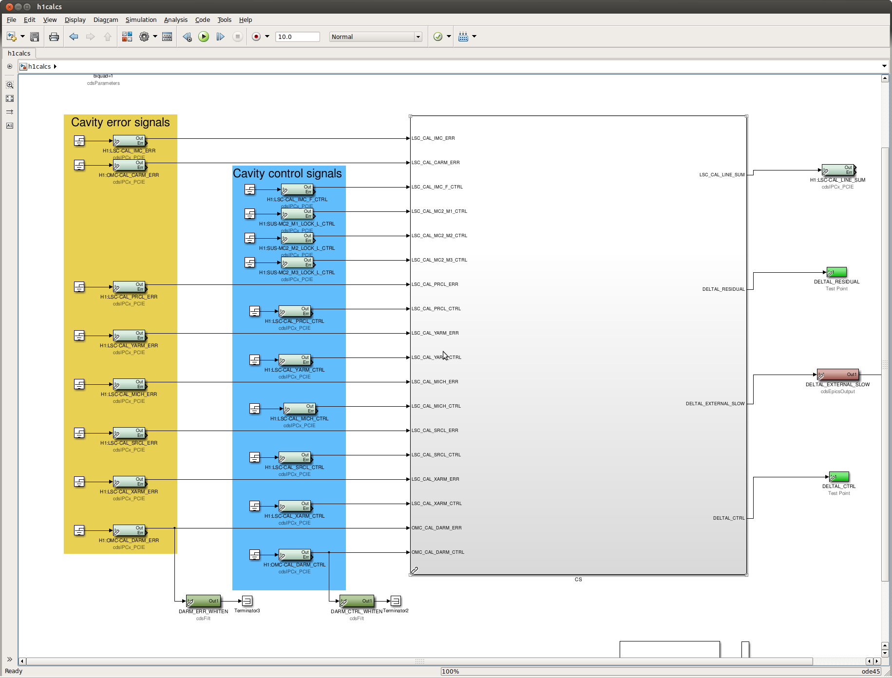
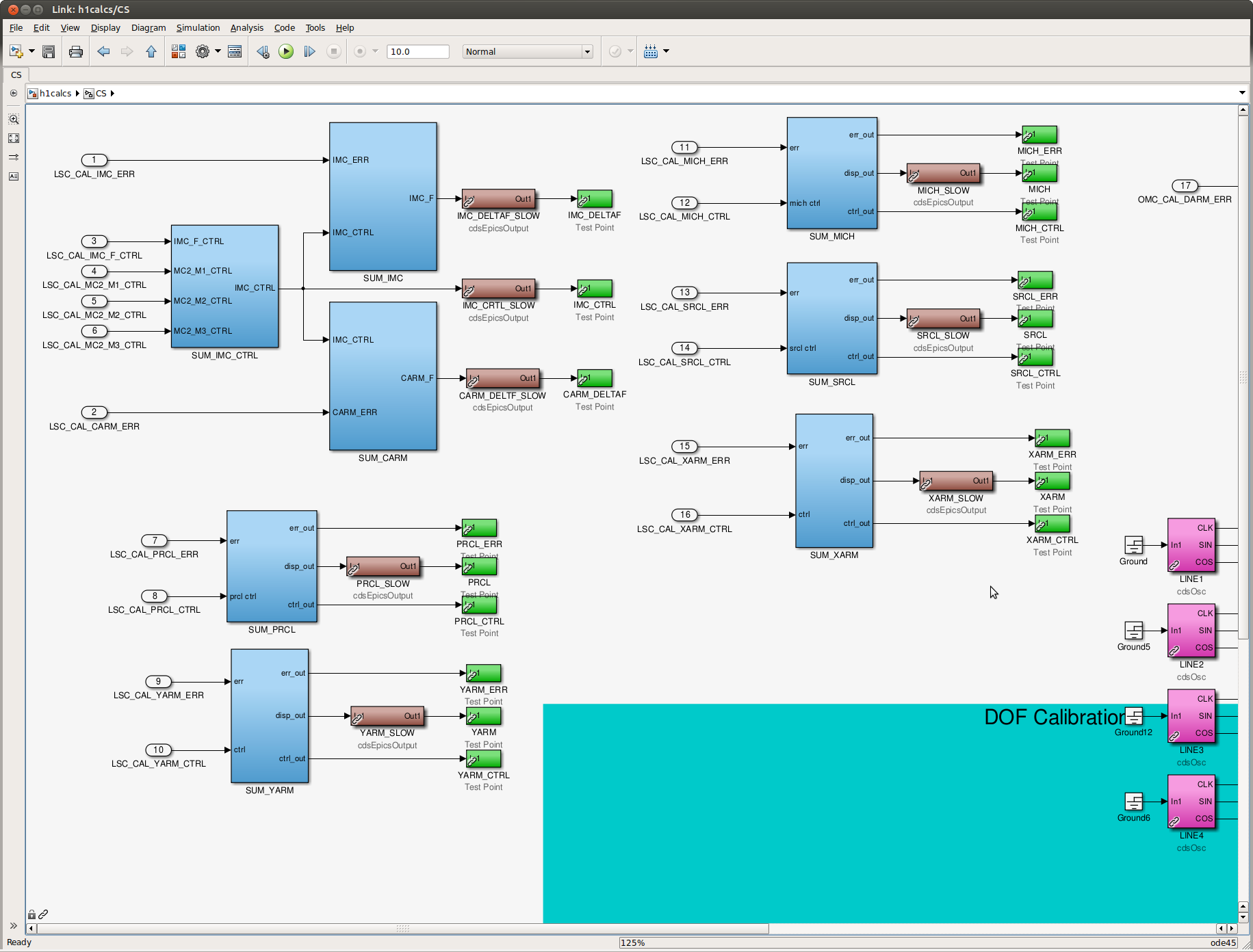
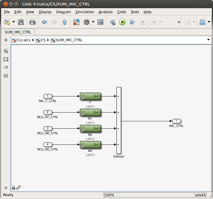
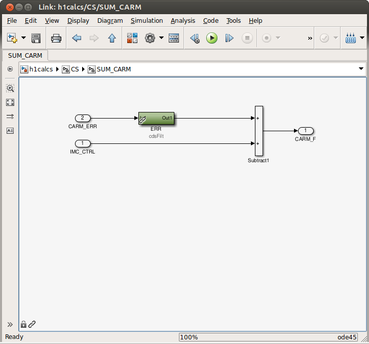
J. Kissel

While poking around the CAL-CS model after the recent changes (see LHO aLOG 17034), I noticed two things:
(1) All of the EPICs settings had been lost, even though I'd made sure to capture a safe.snap of the model before restarting the front end model. Not sure what happened there. In the mean time, I've burtrestored the model to 02:10a PST (i.e. before I got started, while DARM was locked, happy, and producing megaparsecs), which hopefully has captured / restored most of Kiwamu's hard work (LHO aLOGs 16698, 16733, 16780, 16798, and 16843).

(2) Because of a version control mix up in the CAL_CS_MASTER.mdl library part, the names for the whitened versions of the closed-loop and open-loop DARM displacement signals, i.e. (what are now) H1:CAL-CS_DARM_RESIDUAL_WHITEN and H1:CAL-CS_DARM_DELTAL_EXTERNAL_WHITEN have changed since we last updated the h1calcs model. The bank names are now typo free -- but that means I've had to re-install the 1^5 : 100^5 (5 zeros at 1 [Hz], 5 poles at 100 [Hz]) whitening filter used to get above the double precision noise in frame storage (see LLO aLOG 16789).

Maybe I'll ask my fellow detector engineers to help me get an SDF system up and running for this model, so we can better track the changes.
Comments related to this report