J. Kissel, H. Radkins,

Digging deep on the HEPI Pump Servo noise, we measured the voltage amplitude spectral densities of both pressure sensor signals right as they enter the Pump Servo box with a breakout board, some clip leads, and an SR785. The results confirm our suspicion -- the pressure sensor voltage is WELL below what is reported by EPICs. So, it's either the Athena II's ADC noise (1e-2 [V/rtHz] ?? -- seems too high even for a crappy ADC), or some nastiness in turning these channels into EPICs channels. See attachment.

In order to get the pressure sensor signal voltage above the readout noise floor without saturating the ADC, one would need either need to AC couple the signal with a ~ 10 [mHz] high-pass and gain up the signal by an additional factor of 1000, or add a whitening filter; something like two zeros at 1 [mHz] and two poles at 50 [mHz]. I don't know anything about electronics, but I think I know enough that such filters would be difficult to construct at best.

These pressure sensors clearly were not meant to be anything more than DC sensors, so if we intend to keep using them as is, we should lower the unity gain frequency of the pump servo to WELL below 10 [mHz] (along the lines of what Hugh started to do in LHO aLOG 16466). Up to this point, we've been simply injecting terrible ADC noise into the pumps. This explains why the *very* low frequency response and DC values add up, but anything to do with the spectral densities are just injecting this bad ADC noise into the pumps. We still have to make sure the PID parameters are being employed in the units we expected them to be by the CALC record, but tomorrow's another day.

Note -- I'm not yet sure how Rich took his data, but from what I see, both the supply and return sensors are above my measurement noise floor, but the return pressure is significantly (as much as a factor of 5 @ 10 [mHz]) below Rich's eye-ball fit to the noise he measured in SEI aLOG 688.

--------
Details:
Measurement --
With the pump servo in manual mode (i.e. feedback PID loop OPEN), we inserted a DB9 breakout board in-line with the pressure sensor inputs to the HEPI pump servo (channels 1 [supply] and 2 [return], successively). As directed by the pinout in D0901559, independent clip-doodles were connected to pins 4 & 6, the positive and negative legs of the differential signal (with the shield / black clips clipped to pins 7 & 8, which are the pressure preamp's GND returns). These two legs were then fed into the A and B ports of Channel 1 of the SR785, which was set to A-B mode. Other relevant parameters:
Freq: SPAN 3.125 [Hz], LINES 800, LINEWIDTH 3.9 [mHz]
Input: INPUT CONFIG A-B, DC Coupled, INPUT RANGE 20 dBVpk
Disp Step: UNITS -- db units OFF, Pk units RMS, PSD units ON

This measurement was done with the supply line sensor, the return line sensor, with one of the 100 [ohm] resistor plugs from , and finally the SR785 noise floor was determined by sticking 50 [ohm] plugs on the A and B inputs (using the same input range for all measurements -- though I did confirm that the return ASD did not change, and was still above the SR785 noise floor when the input range of 2 dBVpk).

Calibration --
The signal chain goes as follows:
     Pressure Sensor            Pressure Preamp          Diff 2 S.E.              ADC            EPICs Calc Record
100e-3 / 300 [V_diff/PSI]    151 [V_diff / V_diff]    2 [V_se / V_Diff]    2^16 / 20 [ct/ V_se]  0.0032 ["PSI"/ct]
The SR785 voltage was measured just before the Diff 2 S.E., instrumentation-amplifier, factor-of-2 in the HEPI pump servo.
So
- to calibrate the 100 [ohm], input terminated signal ASD as reported by EPICs into single-ended ADC input voltage, one needs
EPICS ["PSI"] ( * (1/0.0032) [ct/"PSI"] * 20 / 2^16 [V_se / ct] =  0.0477 [V_se / "PSI"] ).
- to calibrate the differential SR785 voltage into single-ended ADC input voltage, one needs
SR785 Voltage [V_diff] ( * 2 [V_se / V_diff] = 2 [V_se / V_diff] ).
- to calibrate the differential SR785 back to PSI at the sensor,
SR785 Voltage [V_diff] ( * (1/151) [V_diff / V_diff] * 300 / 100e-3 [PSI / V_diff] = 19.8675 [PSI / V_diff] )

What did else did I learn today?
- The EPICs calc record defines the sampling frequency to be 10 [Hz]. EPICs data is normaliy stored at 16 [Hz]. That means the features seen in the EPICs spectra (the ~1.6 [Hz] and harmonics notches) could just be Fourier reflections NOT features in the plant. I don't know what the native rate of the Athena II ADC is, I have an email out to Ben. But there is certainly some sort of nasty aliasing / imaging nonsense going on.

- The .ini files that determines which channels are stored in the frames for these pump servos lives here:
/opt/rtcds/lho/h1/chans/daq/
H1EDCU_HEPIPUMPL0.ini
H1EDCU_HEPIPUMPEX.ini
H1EDCU_HEPIPUMPEY.ini

- The CALC record that calibrates the EPICs channels from [ct] to [PSI], and also defines the sampling rate which the records are picked off of the ADC lives in
/opt/rtcds/lho/h1/target/h1hpipumpl0/h1hpipumpl0epics/db/
a.12.db

- An SR785's high-pass for its AC coupling mode is at 160 [mHz], so for these low frequency measurements, I sure-as-heck need to be DC coupled, and that limits my choice of input range, since *actual* DC signal is clearly what dominates these pressure sensors.

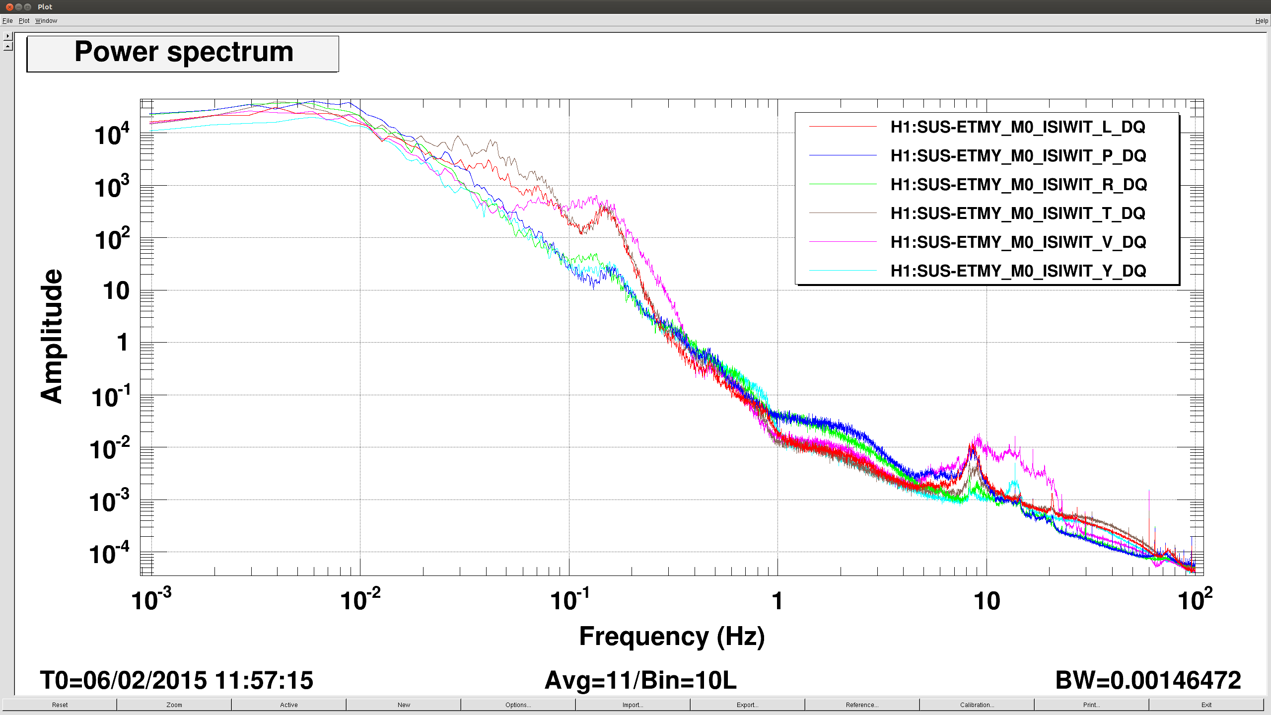
What new ETMY L2P are you referring to?? We found no filters engaged and a gain of 1.0, and the output OFF.
The tidal feedback goes to L1 state. Locking the Y-arm on green and engaging the slow servo caused a really bad L2P with the above configuration. We did a burt restore to yesterday morning (L1 L2P FM8 z0.5p10 gain -1, output ON), and everything is fine now.
The EY L1 L2P state that I found this morning is not what Ryan designed last night ( FM9 (zpk([],[0.5],1,"n")gain(0.001)), Gain 1 and output ON). However, this does not work with the slow servo on.
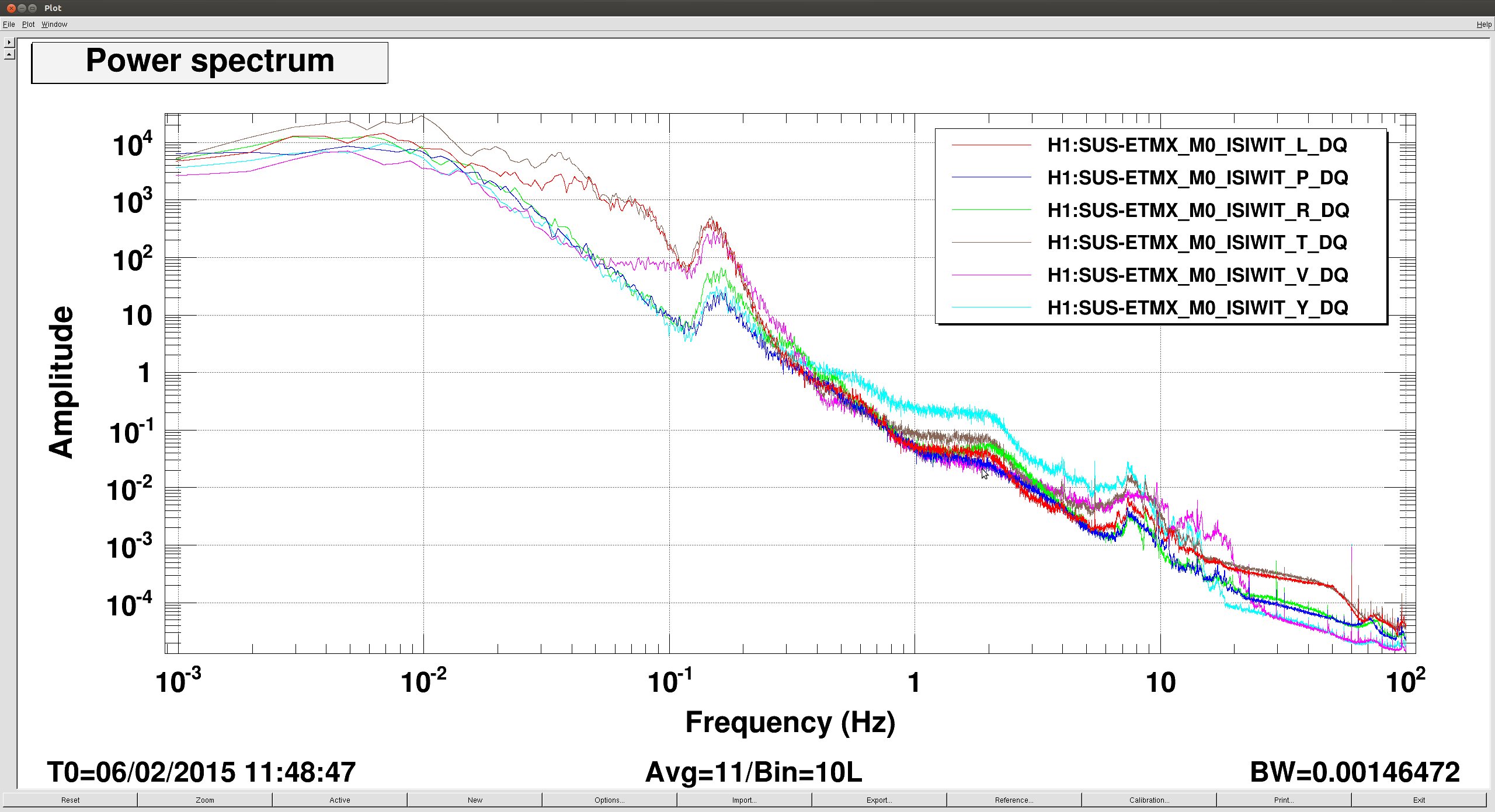
The EX L1 L2P FM9 was installed zpk([],[0.5],1,"n")gain(0.001). The overall filter gain remained 5.2. Not much invesitgation has been done, but based on the green transmission dips, it seems that the old FM10(-60dB) setting is better.
Elli, Evan
We have taken a TF for the DHARD pitch plant. Now filters are installed in ETMX/Y L2 LOCK P which invert this plant.
With the DHARD loop open (and oplev damping engaged), we drove band-limited white noise (up to ≈4 Hz) into DHARD EXC, which drives the ETM PUMs differentially in pitch. We then measured the transfer function DHARD EXC → DHARD IN1. This gives the plant transfer function for the DHARD loop, which we then fit by eye in Matlab to a zpk model.
The fit is not so great in phase above 0.5 Hz, but maybe as a first try it is good enough to allow us to bump up the DHARD bandwidth anyway.
The filter modules are FM6 and FM7.