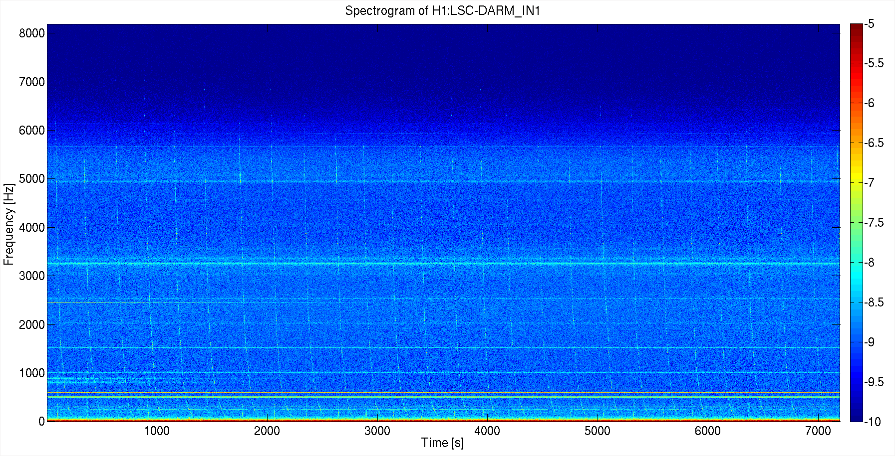
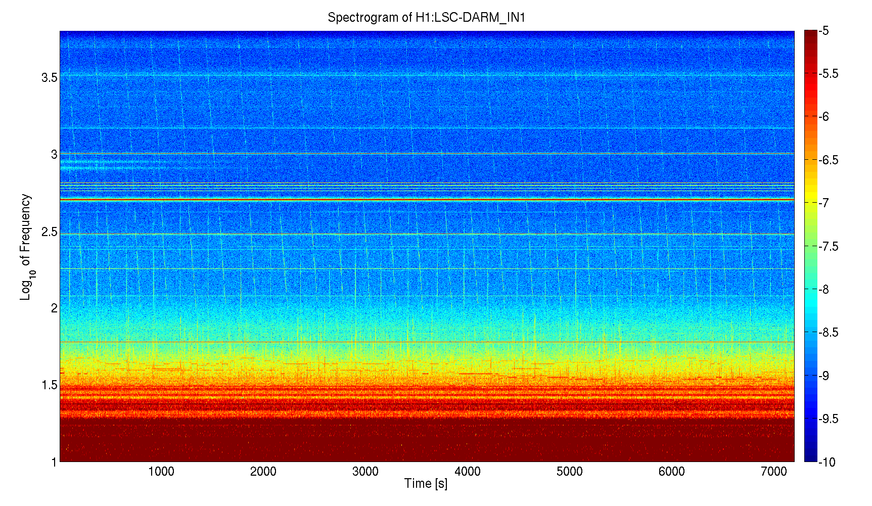
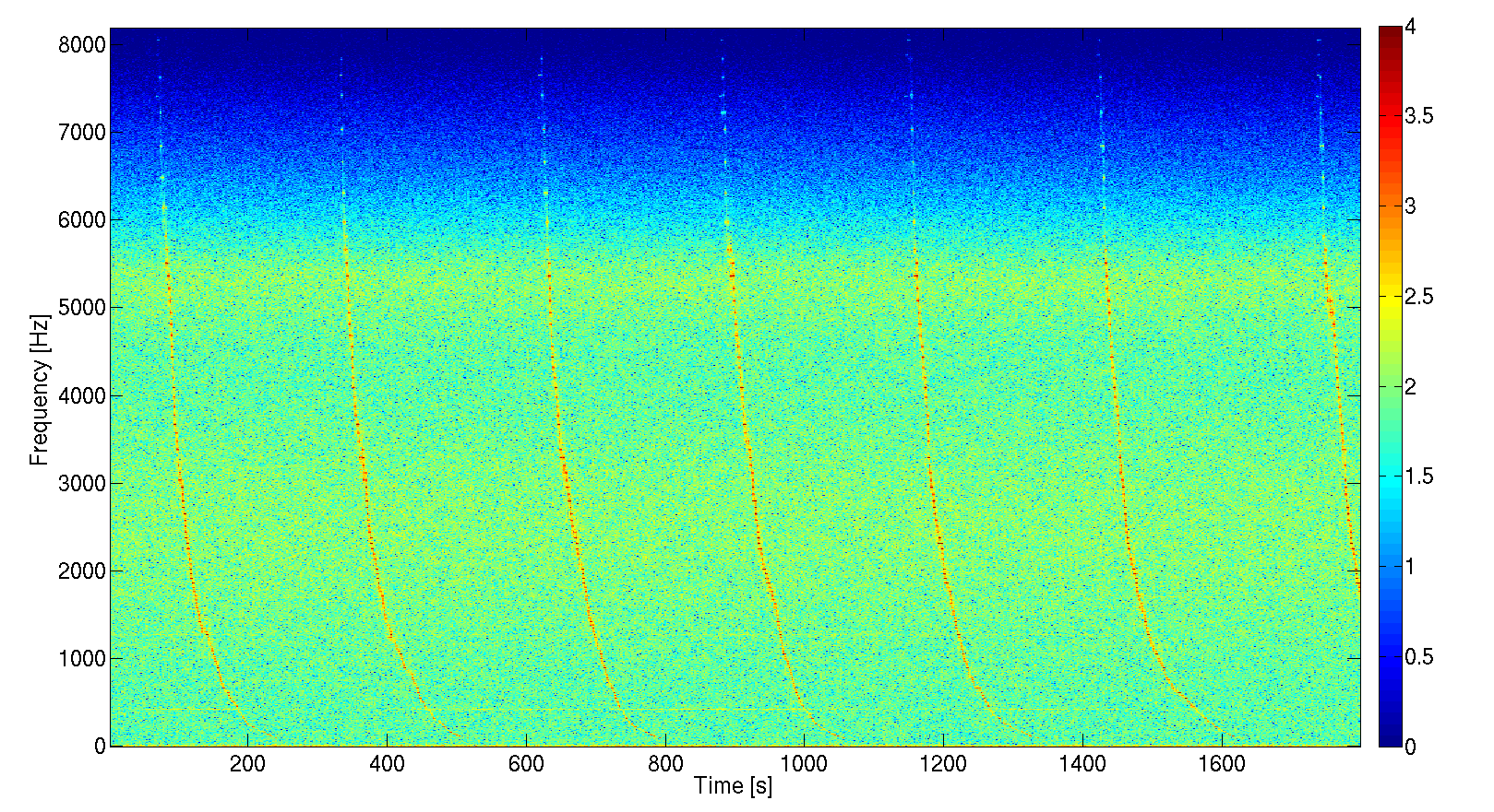
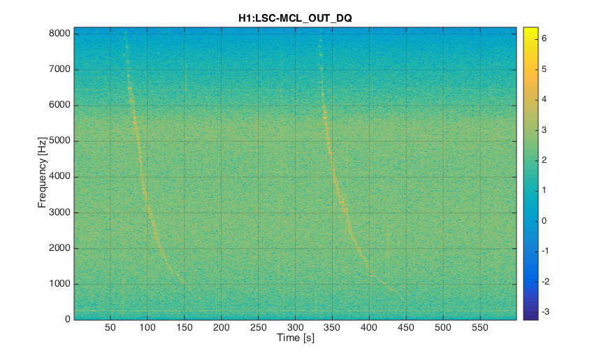
Last night we noticed, looking at the real time spectrum of DARM, that there was a wandering line. The attached spectrograms show the peculiar behavior: about every 270 seconds (not regular) this line enter the spectrum from the high frequency range and moves down in a quite repetible way (the frequency has quite perfect exponential evolution with time). Then there is some sort of burst of noise before the line starts again from the high frequency.
This behavior seems different from the wandering line related to IMC-F seen at Livingston.
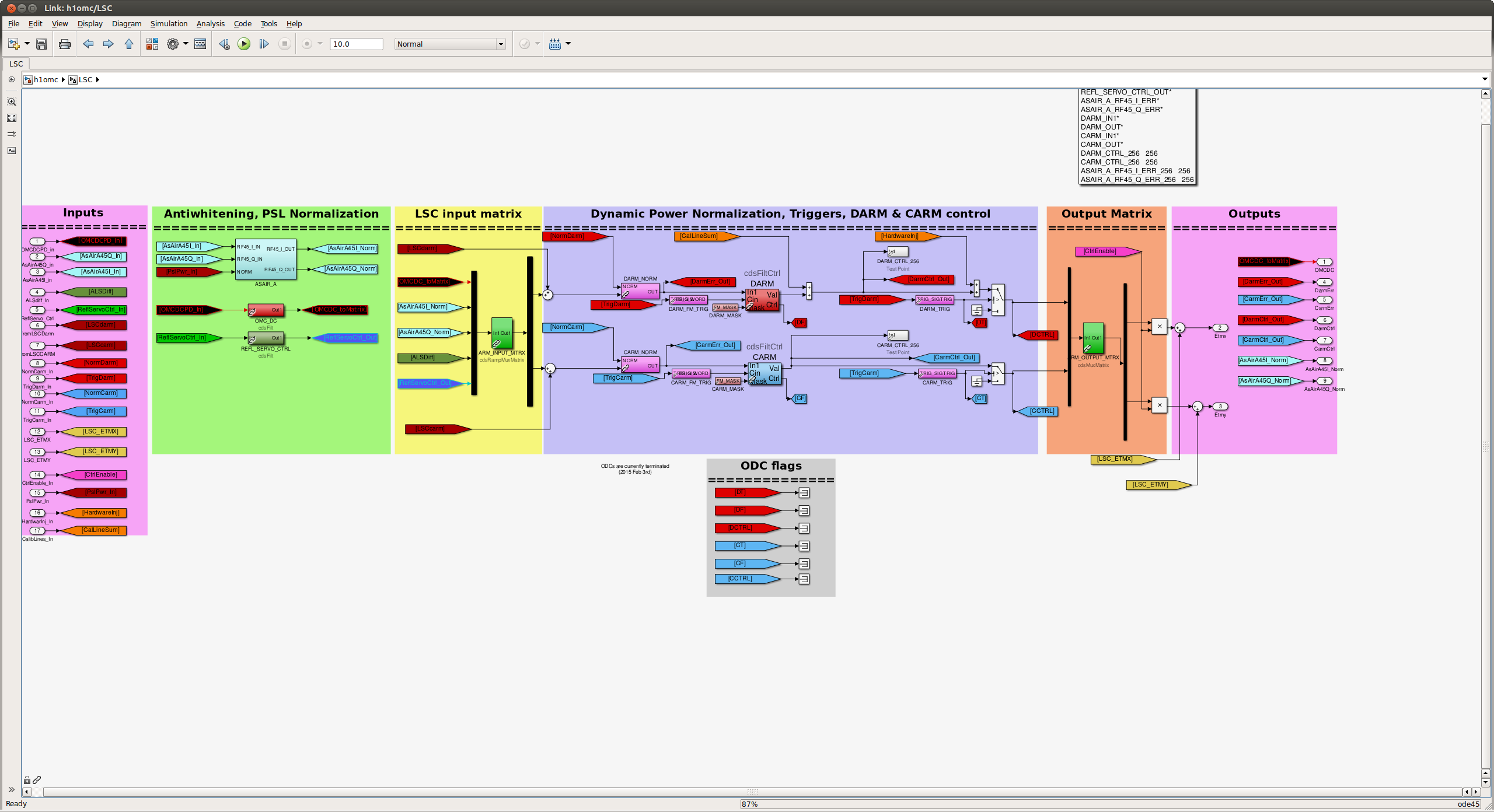
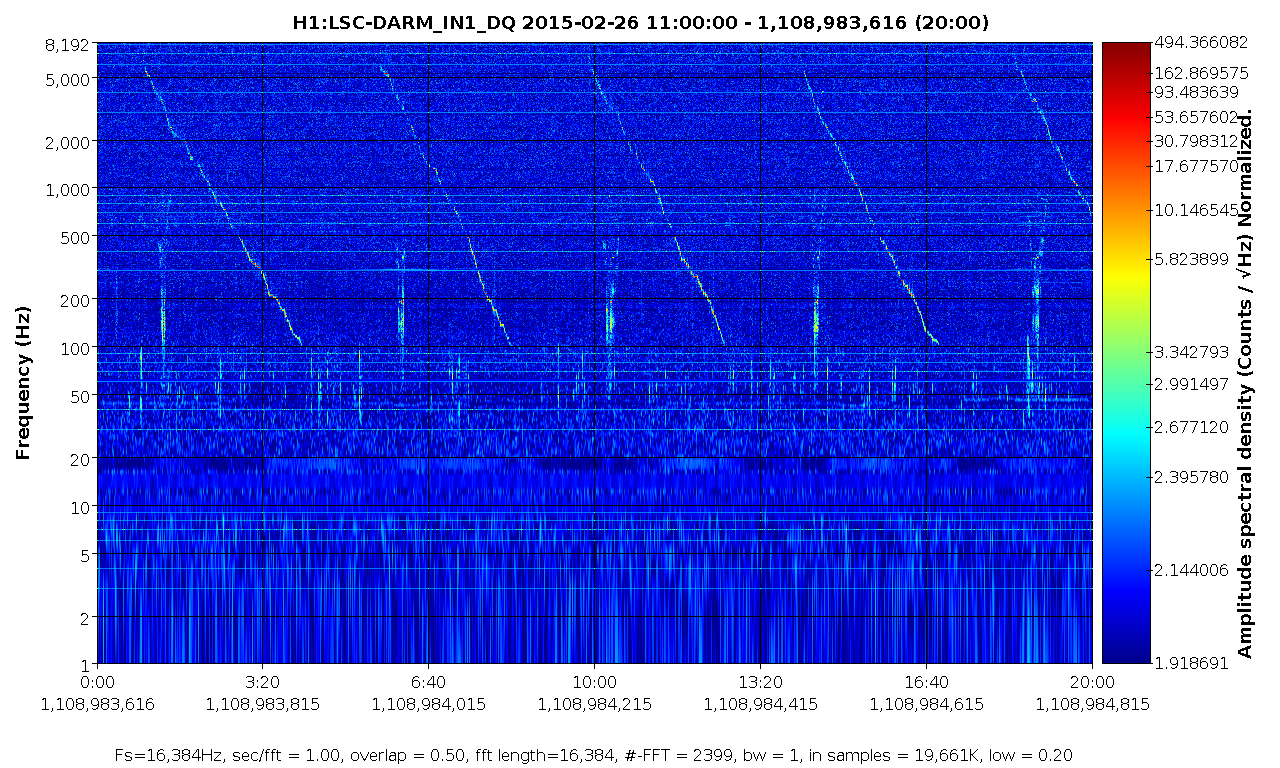
I was just looking at the same feature. The burst of noise looks like a beatnote whistle, similar to what we saw at Livingston with IMC-F. At first glance, it looks like the whistle is occuring when the drifting signal crosses through the OMC length dither at 3.3kHz. I'm attaching a few spectrograms zoomed on to various levels to look more closely at the feature. The frequencies look discrete when you zoom in, it doesn't seem to be a continuous signal. Was there some kind of swept sine injection that was unintentionally left on during the lock?
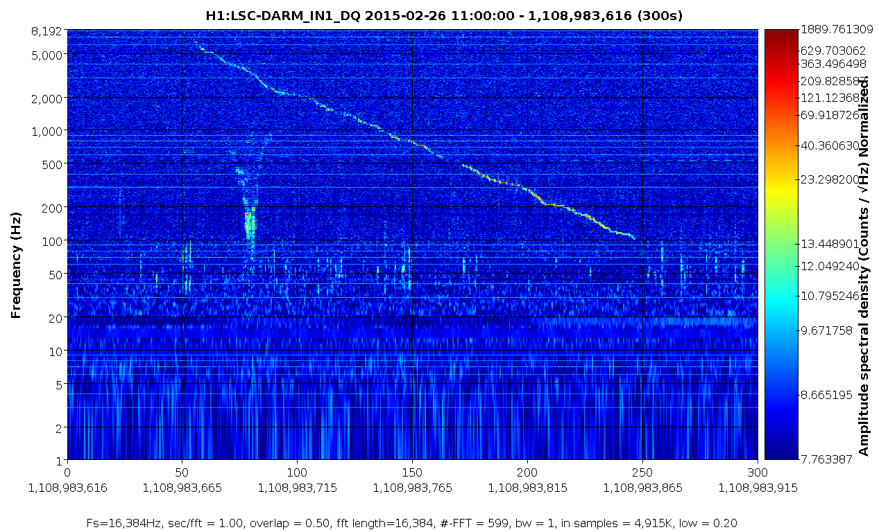
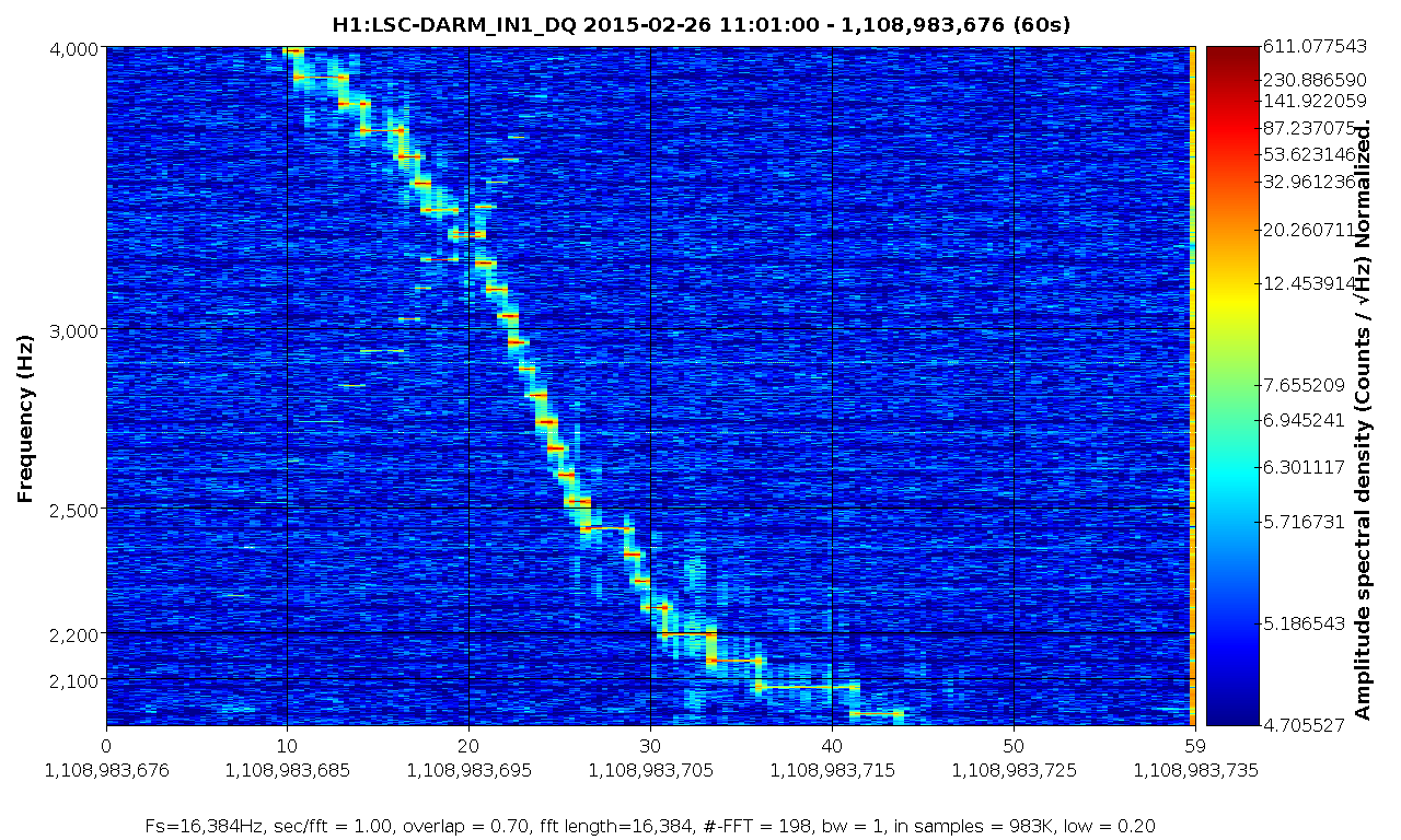
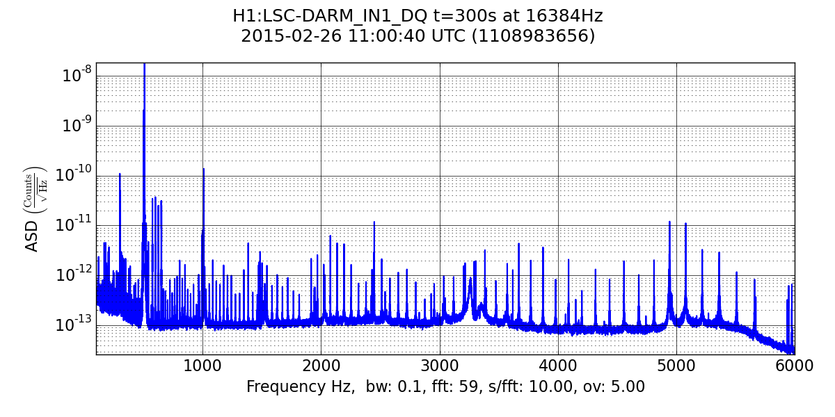
I plotted a spectrum long enough to catch all of the frequencies of the signal as it swept down. The placement of frequencies seems more sparse at higher frequencies and becomes more densely packed as it dips below the kHz range.
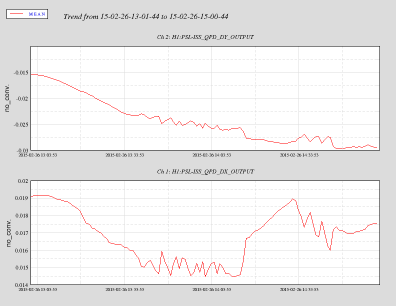
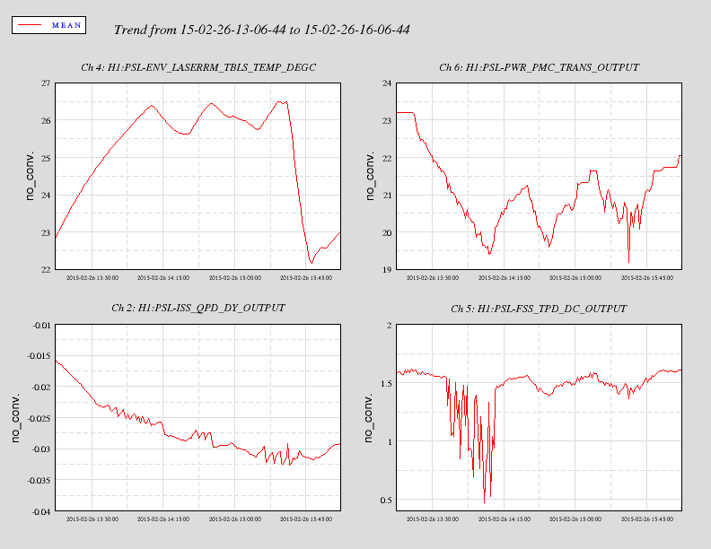
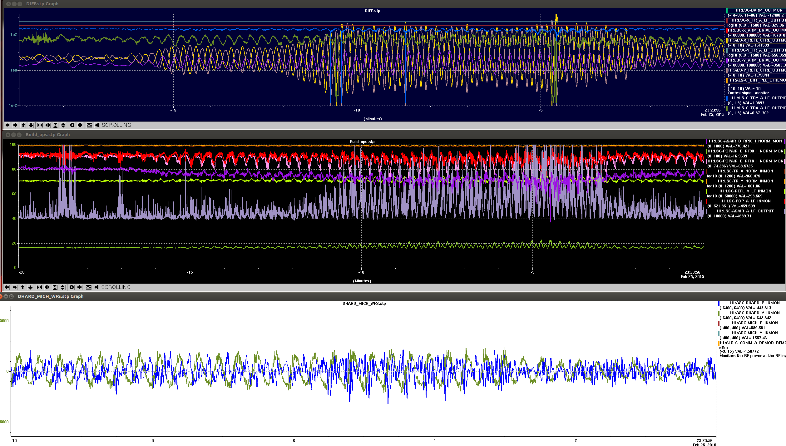
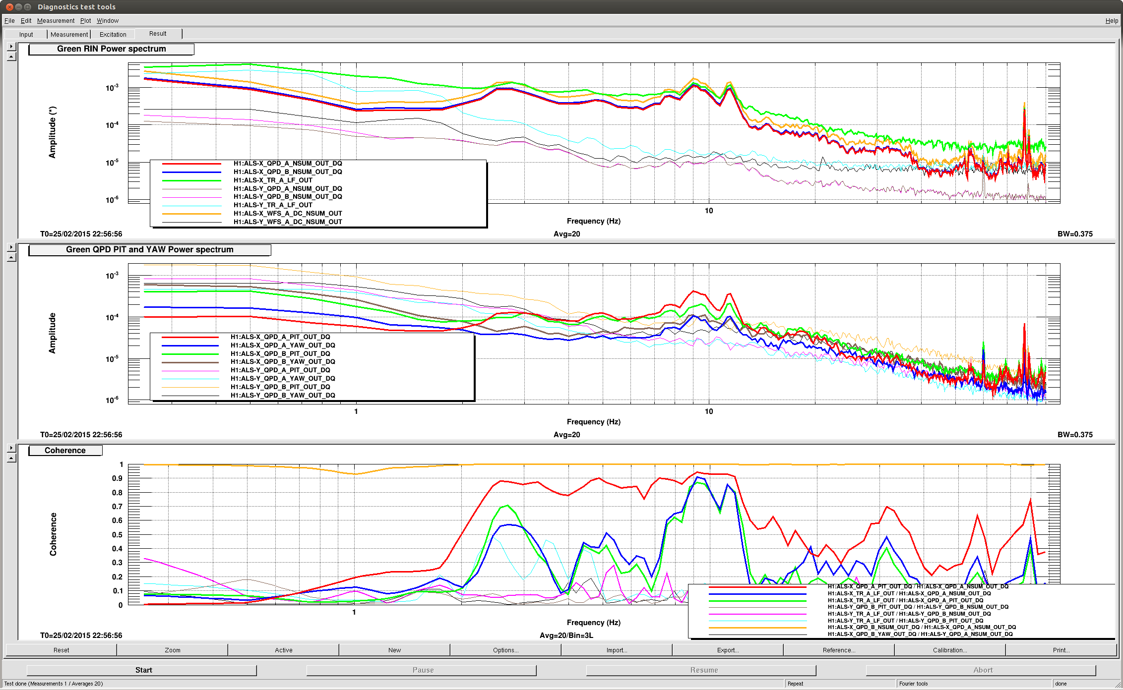
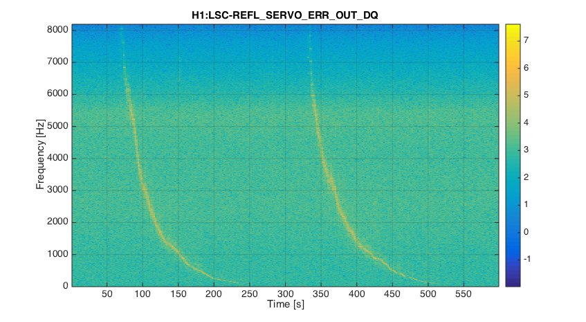
The feature is visible in REFL signals as well, hinting in the direction of something going on in the laser. It's visible as well in LSC-IMCL and LSC-REFL_SERVO_ERR
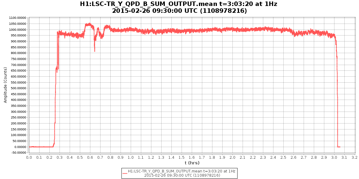
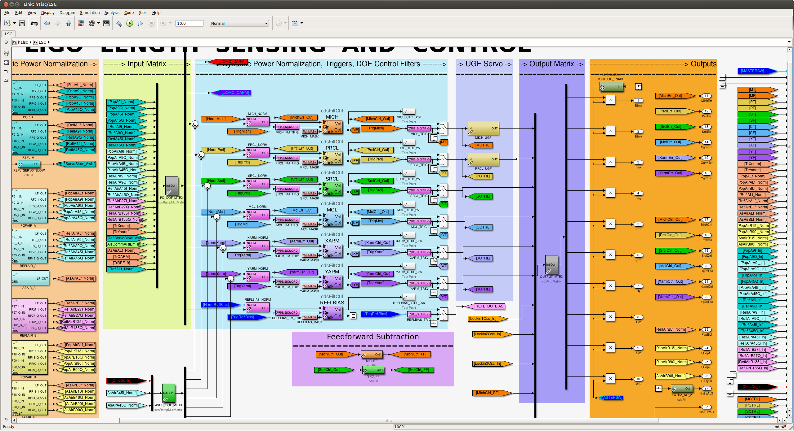
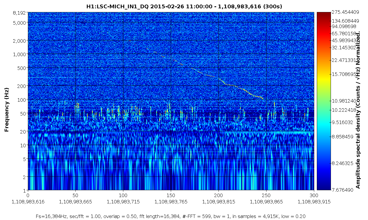
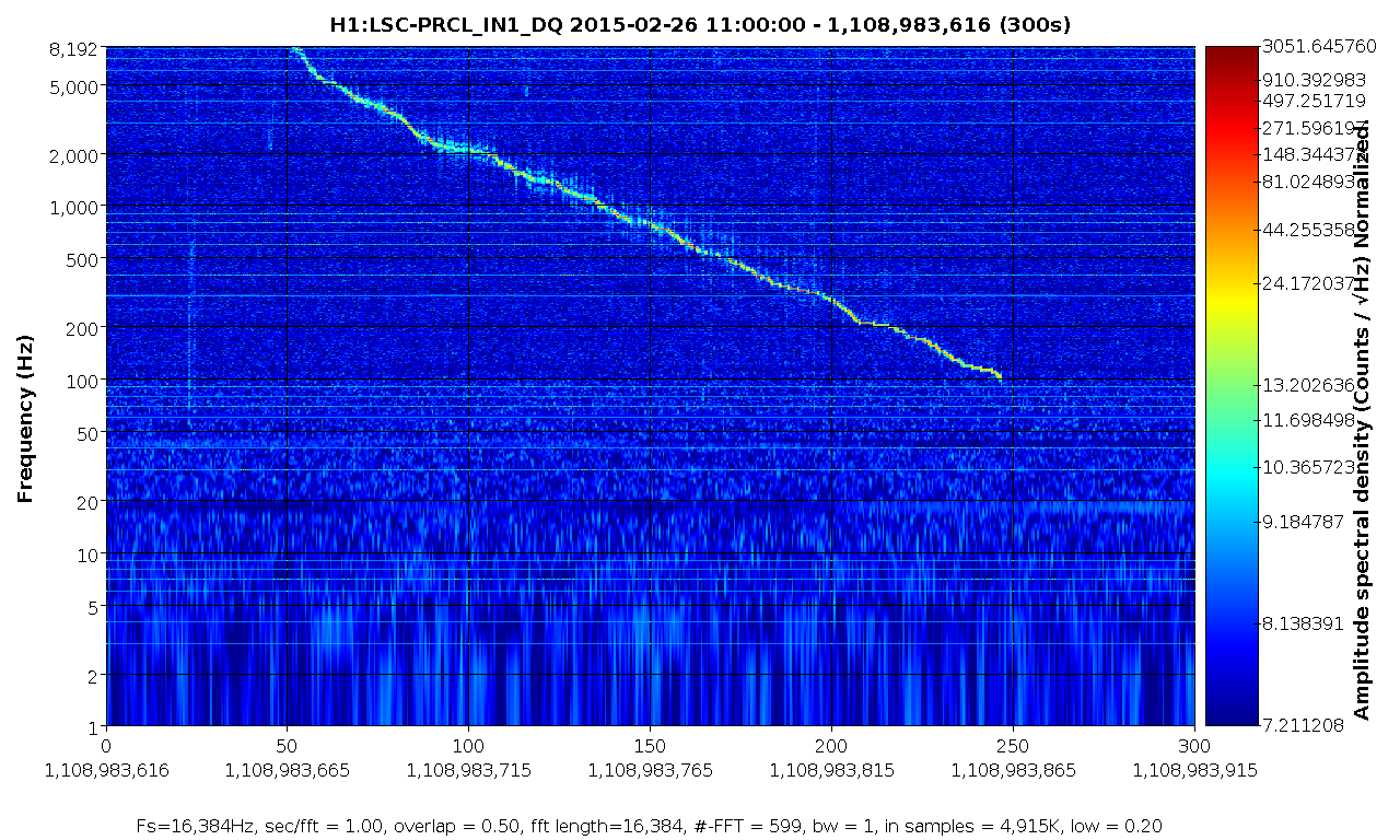
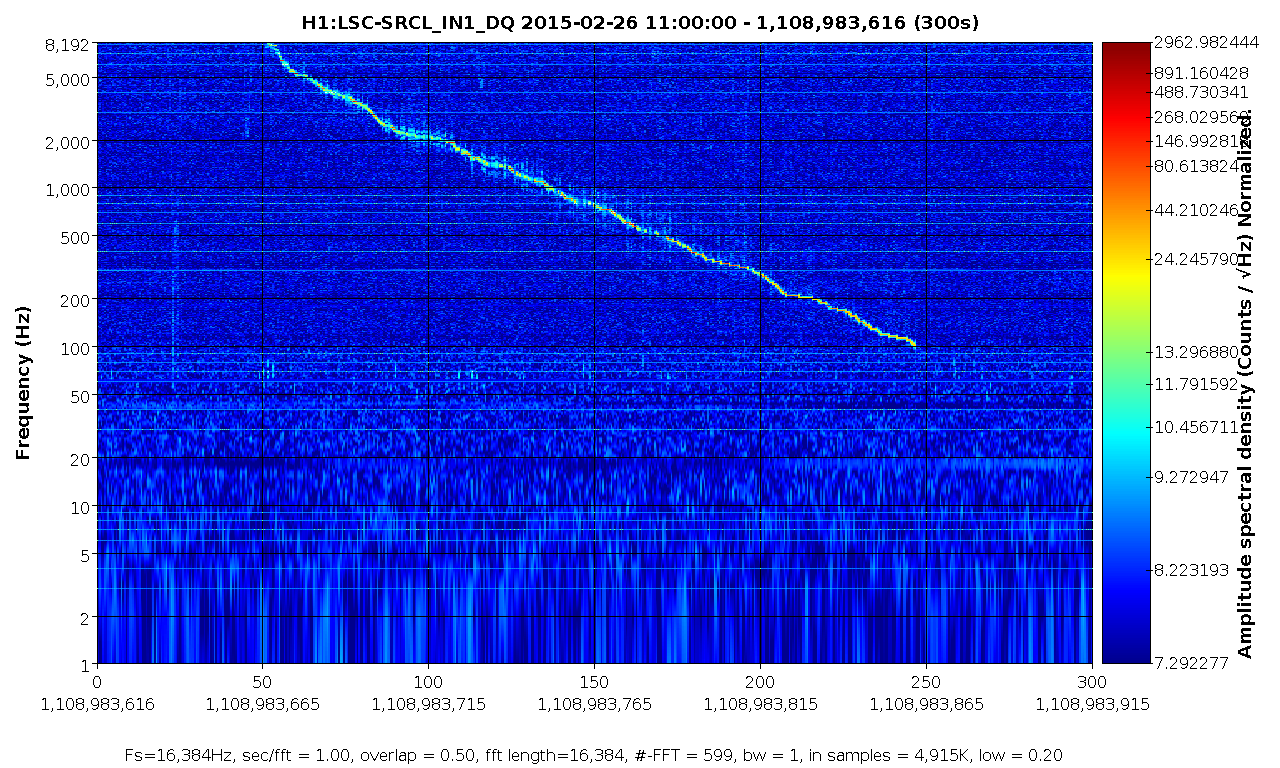
This feature is showing up in MICH, SRCL, and PRCL. It's more faint in MICH, but is very strong in PRCL and SRCL. It's also showing up in the input to BS M3 LOCK filter for the length DoF, but it looks like MICH was being used to feed back on the BS position. I didn't see any evidence of the signal in MC2 trans, IM4 trans, IMC-F, or the IMC input power.
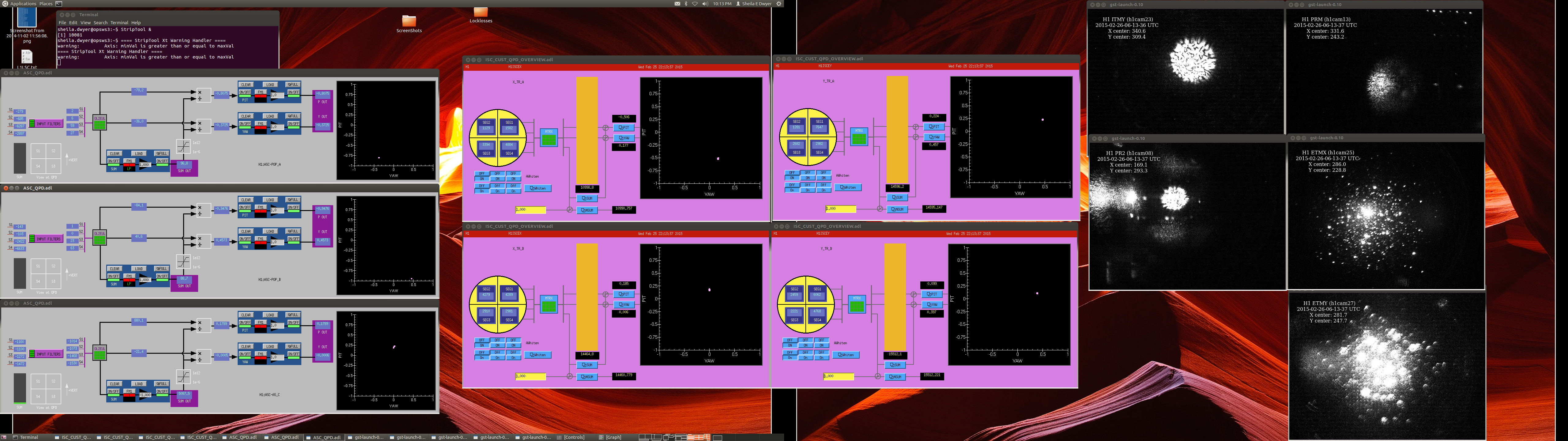
Problem solved: a SR785 was connected to the excitation input of the common mode board, and the excitation was on. We disabled the excitation input from the common board medm screen