Kiwamu, Dave, Evan, Betsy, Elli
Today we locked SRMI in preparation for measuring the SRCL guoy phase. The lock is not particularly robust, but we are hoping it will be good enough to takea preliminary measurement...
Initial settings:
MICH is locked to LSC-ASAIR_A_LF with input matrix value 0.25, a H1:LSC-MICH_OFFSET offset of -200, a gain of H1:LSC-MICH_GAIN 1600 (or locking with gain 800 then ramping up to 1600 also works), and an output matrix value of 1 going to BS. FM7 (zpk([1],[150;75+i*129.904;75-i*129.904,1,"n")) and FM9 (ELP40) are on in the MICH loop.
SRCL is locked to LSC-REFLAIR_RF9_I with an input matrix value -3.75, H1:LSC-SRCL_GAIN gain of -50000, a SRCL offset of 0 and an output matrix value of 1 going to SRM. FM9 (zpk([10],353.553+i*353.553;353.553-i*353.553,1,"n")gain(10)) and FM10 (cheby1('LowPass",2,1,300)) are on in the SRCL loop.
Trigger settings are:
MICH: triggered by ASAIR_A_DC gain 1, upper thereshhold 1000, lower threshold 400. Filter trigger thresholds On:1000 Off:400, 1seconds, FM2 triggered. (FM2 is zp1:0)
SRCL: triggered by ASAIR_A_DC gain 1, upperthreshold -1000 lower threshold -1000. Filter trigger threshold On:400 Off:400, 0.2seconds, FM2 and FM3 triggered. (FM2 is zp1:0 FM3 is zpk([1],[0.1],10,'n')resgain(0.684,3,10).)
Aquiring lock:
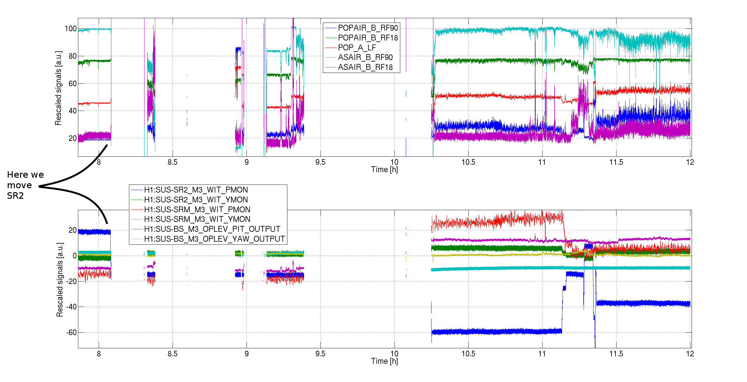
We are kind of triggreing the whole thing manually by setting up the above initial settings, and then turning off H1:LSC-CONTROL_ENABLE so no control signals are passed from the LSC output matrix to the suspensions. If we don't do thisthe optics get kicked around and we don't lock. We wait untill the AS_AIR flashes look slow (~1Hz) and then turn on H1:LSC-CONTROL_ENABLE. About 20% of the time we then aquire lock (or we try again). It is taking <1min to lock.
After aquiring lock:
Engage FM4 (zp 4:0). Lock stretches are lasting for a few minutes in this configuration, longest locks~10 mins.
Also:
-The MICH bounce mode keeps ringing up at 17Hz so we have been damping it every now and then using by turning H1:SUS-BS_M2_VRDAMP_P filter.
-Flashes of SRMI were reaching the H1:ASC-OMC_A/B qpds which was moving OM3. We disabled the feedback to OM3 by setting the H1:OMC-ASC_POS gains to zero. These gains have been returned to their previous values.


We think we have identified the source of the problem and devised a relatively simple remedy. See aLog 17145.