kyle.ryan@LIGO.ORG - posted 15:57, Friday 27 February 2015 (16987)
BSC1 annulus ion pump (circa 2002) died -> Will replace at next opportunity
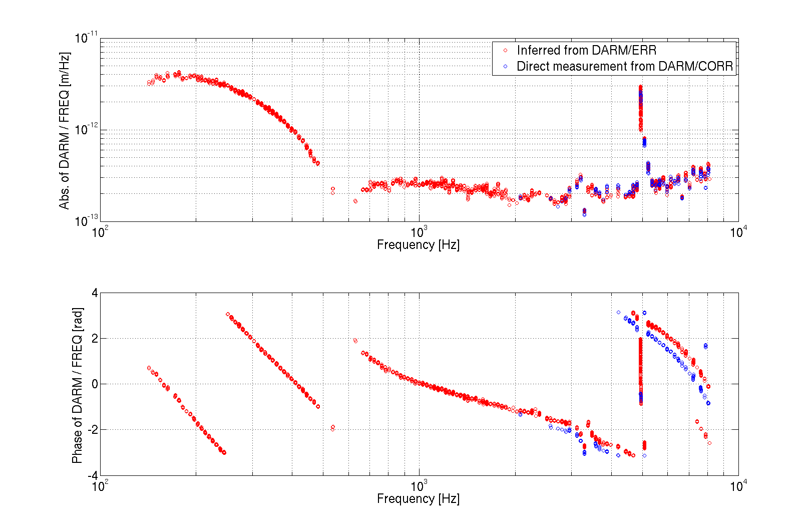
Using the swept sine injection that was going on during the last DC readout noise, I tried to estimate the coupling of frequency noise to DARM.
It turned out ot be quite large, at the level of 2e-13 m/Hz above 1 KHz (see first plot). After some discussions and more thinking, we realized that if the IMC longitudinal locking point is not perfectly tuned to the top of the resonance, the IMC will convert frequency noise into intensity noise, and therefore the measure TF is not really the pure coupling of frequency noise to DARM.
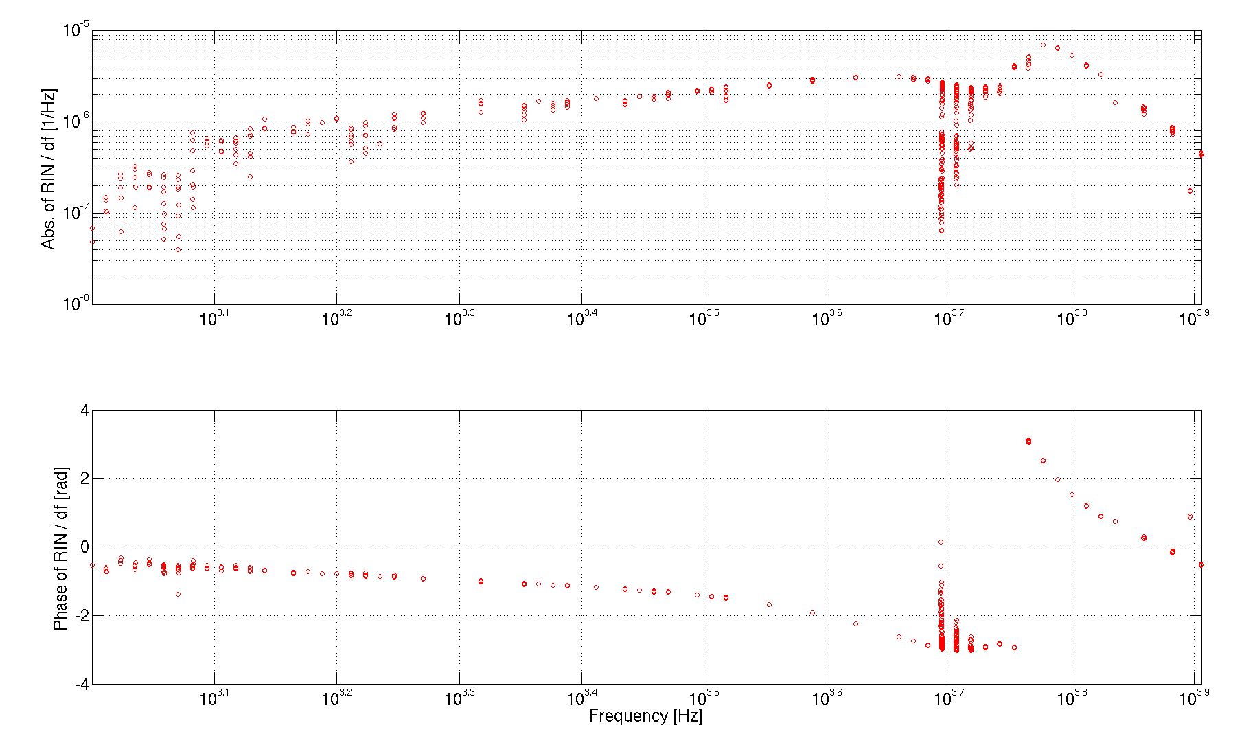
Indeed, the swept sine is very well visible in the IMC transmited power (for example in the ISS signals). I could use the TF from frequency noise to RIN (see second plot) to estimate the IMC longitudinal offset. It turned out to be of the orer of 2e-12 m, which is about 0.5% of the IMC linewidth. This seems quite reasonable. We'll have to retune the IMC locking point in the short term.
This IMC locking offset might be the explanation for the high frequency broad band coherence between DARM and PRCL/SRCL signals.
We were injecting the sweep sine into the common board correction, and we were reading the cocrrection after the injection. I could measure DARM using the calibrated signal CAL-DELTAL_EXTERNAL_DQ (after applying a dewhitening in the form of 5 zeros at 1 Hz and five poles at 10 Hz, DC gain of 1). I could measure the actual frequency board correction using IMC-F_OUT which is calibrated in kHz. In this way, the transfer function from the common board correction to DARM is a direct measurement of the coupling F of frequency noise to DARM. Unfortunately, I could get coherence only above 1 kHz. I could get better coherence between the common board error signal and DARM above 100 Hz. This transfer function is F/G, where G is the response of REFL_9_I to freqeuncy noise at the IFO input. This is described by the double cavity pole, which is quite well described by 1/(1i*f) at frequencies above 100 Hz. So I can match the high frequency of DARM/IMC-F_OUT and DARM/LSC-REFL_SERVO_ERR (corrected for the pole) to get another estimation of F, valid from 100 Hz and up. I also can get a measurment of G which is 6e8 / (1j*f). The result is shown in the first plot.
I can estimate the coupling of frequency noise at the IMC input to intensity noise at the IMC output with the transfer function between IMC-F_OUT and PSL-ISS_SECONDLOOP_SUM14_REL_OUT (which is calibrated in RIN). I get something of teh order of 1e-6 1/Hz at high frequency. The TF is not completely flat, but let's ignore this for the moment being.
If the IMC is locked off resonance, I get a direct coupling of frequency noise to intensity noise given by
dP/p = 32 Finesse^2 L_IMC / (lambda * c) * offset * frequency_noise
So I get the estimate of the offset to be of the order of 2e-12 m, to be compared with the linewidth lambda/4/Finesse = 5e-10 m
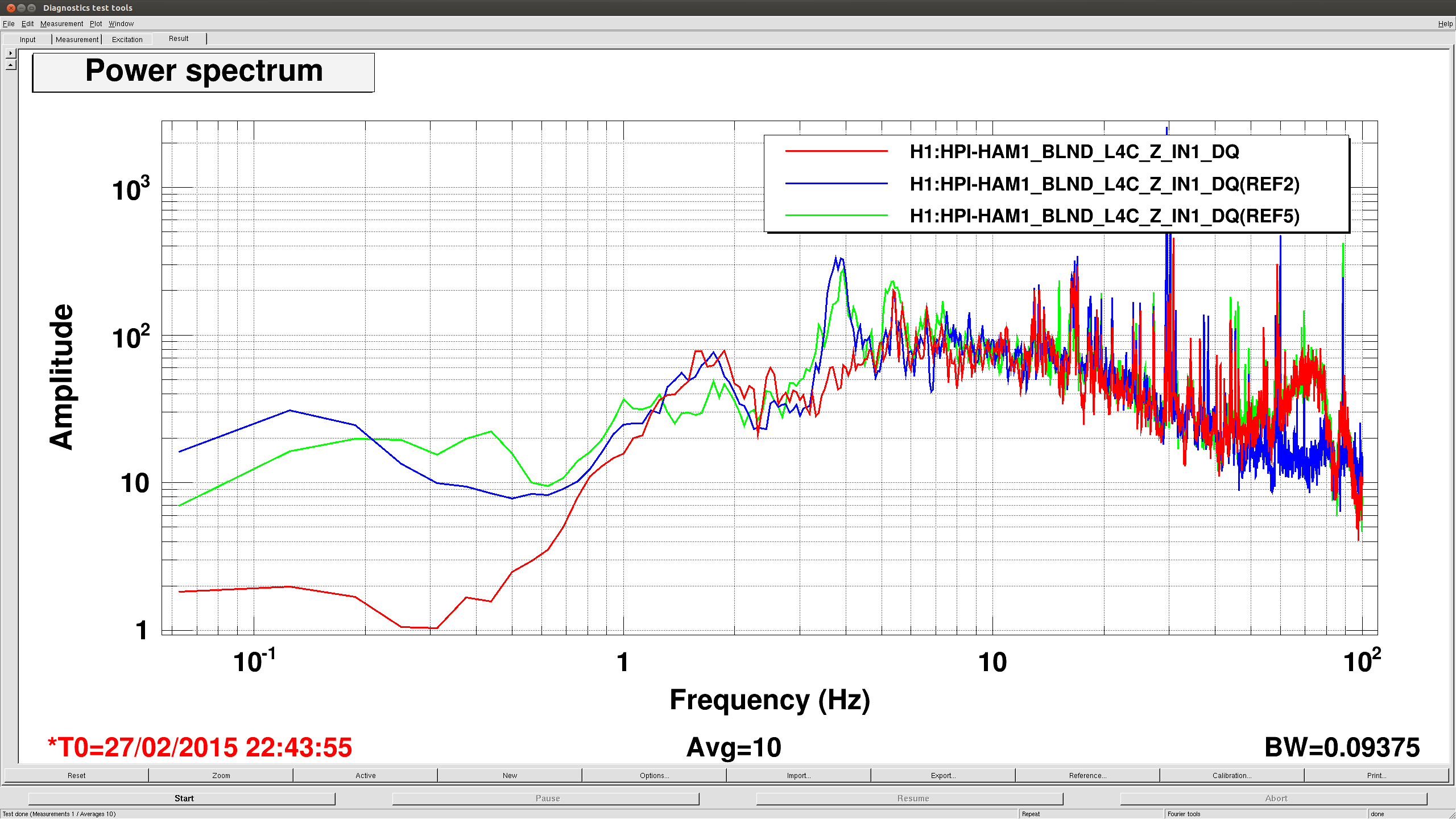
This morning, before anyone got on site to complain about it, Hugh and I unlocked HEPI on HAM1. We then turned on the isolation loops we installed last night. Everything turned on as (un)expected, we were able to steer then table back close to where it was. In addition, sensor correction in Z from the ground STS2 under HAM2 works as well, meaning we get a little inertial isolation below 1hz, something like a factor of 10 at .2hz. Attached plot shows HEPI L4C spectra of 3 states, blue is locked this morning, green is unlocked/isolated, red is isolated with sensor correction. There is probably some contamination from a few hz to 30 hz from Kyle's pump cart (almost touching one of the piers!) and other activites in the LVEA. Or at least I hope that's what explains the big peak at 2-3 hz.
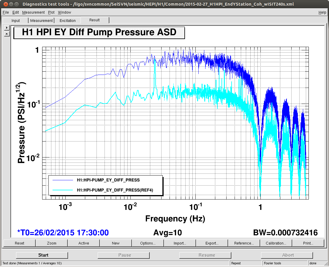
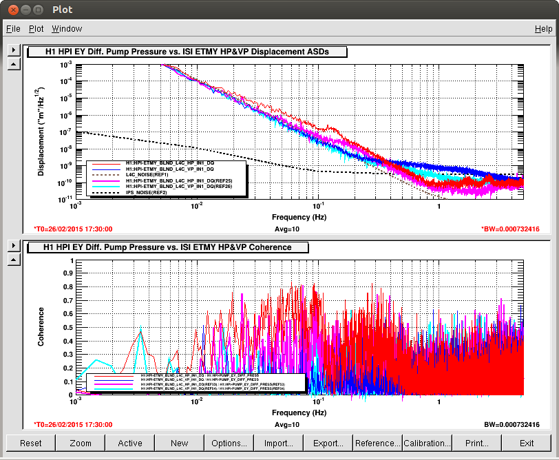
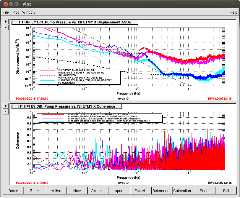
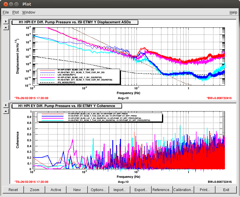
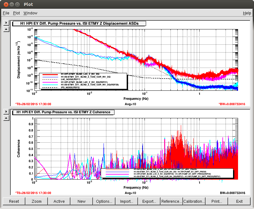
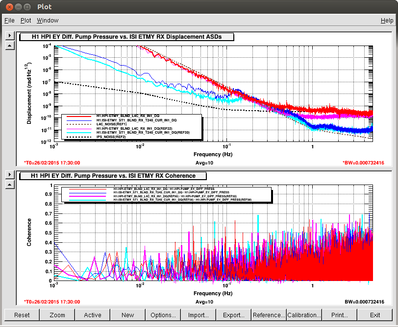
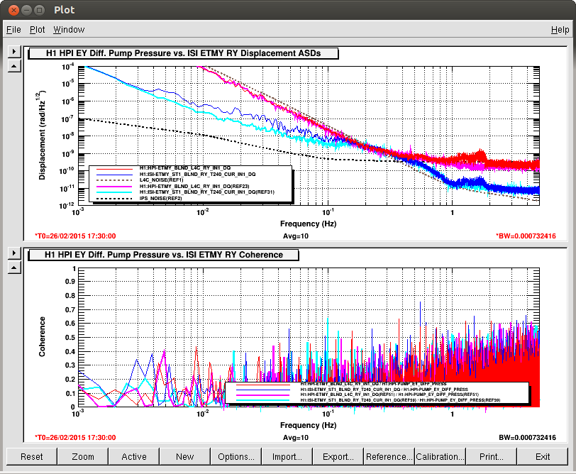
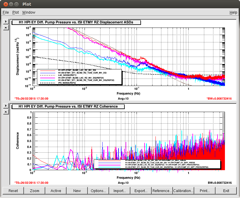
On Tueday, the End Y HEPI Servo Computer Power Supply was ground bounded, and the Accumulators on the Fluid system were charged, alog 16907. On Thursday, I removed the ground strap for ~6 hours to understand if the coherence reduction seen was from the Ground bonding or the Accumulator Charging.
Conclusion: the bulk of the improvement comes from the Accumulator charging.
While there is a minor amount of increased coherence seen in Z and HP it isn't near the amount seen before the Tuesday work especially HP--See the reference traces on 16907. Of course, most of the ultimate noise reduction comes from Jeff's tuning of the controller pushing the ugf down to 10mhz but charging the accumulators and well grounding the servo computer are important too.
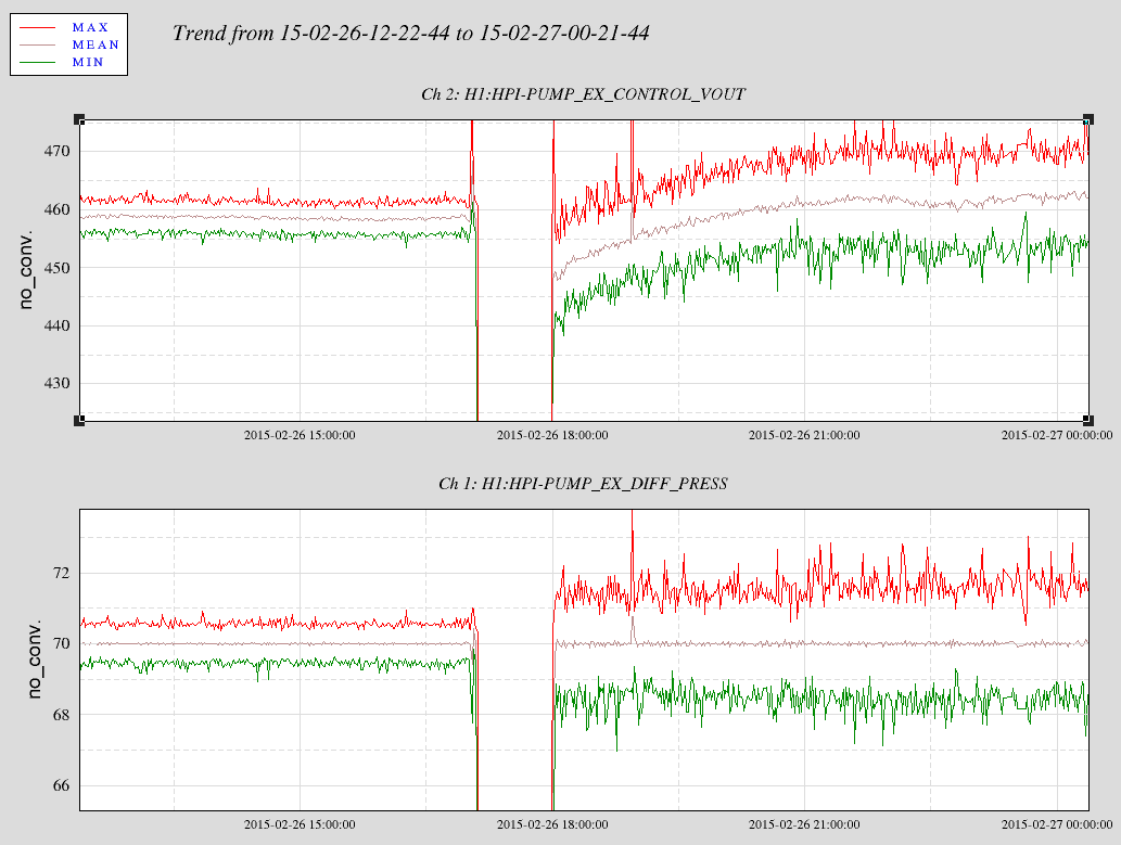
The attached plots have the reference traces as post Tuesday work and the current traces are beginning at 1730utc 26 Feb.
Kyle

HAM1 ion pump OK -> Spun down HAM1 turbo and decoupled pump cart plumbing -> Leaving turbo controller energized and turbo cable connected for now (mag lev rotor levitated and not fully stopped) -> Opened GV5 and GV7

Utilizing the ion pump at this atypically high pressure will marginally reduce its life but is the safest configuration for the vacuum system and is the least disruptive to commissioning
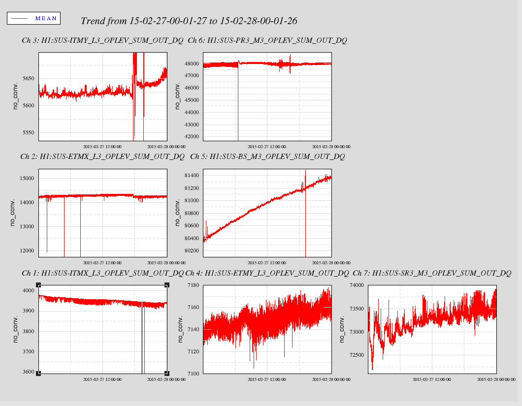
The plots below are the 24 hour OpLev trends
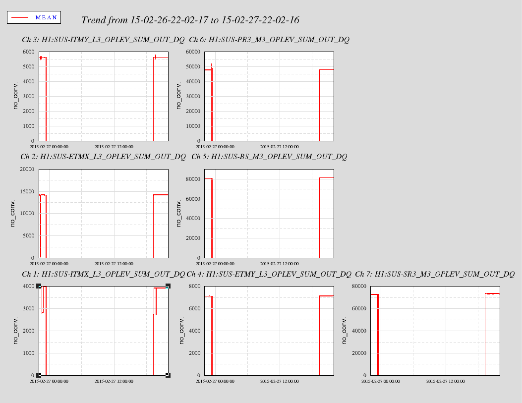
First plots did not show all the data. Reran the the plots and zoomed in to show greater detail. The second plots shows more interesting data. For future plots will continue to zoom.
SudarshanK, GabrieleV, PeterK.
The modifications was made on the ISS second loop power stabilisation board to change the variable gain represented by H1:PSL-ISS_SECONDLOOP_GAIN form 0 to 40dB to -11 to 31dB. This is on top of the addition 20dB gain that was added and reported in alog 14291, and controlled by H1:PSL-ISS_SECONDLOOP_ADD_GAIN.
We also made some modifications on the Guardian scripts that engages the second loop. Now the second loop can be engaged from the IMC guardian window although some fault checking will need to be implemented.
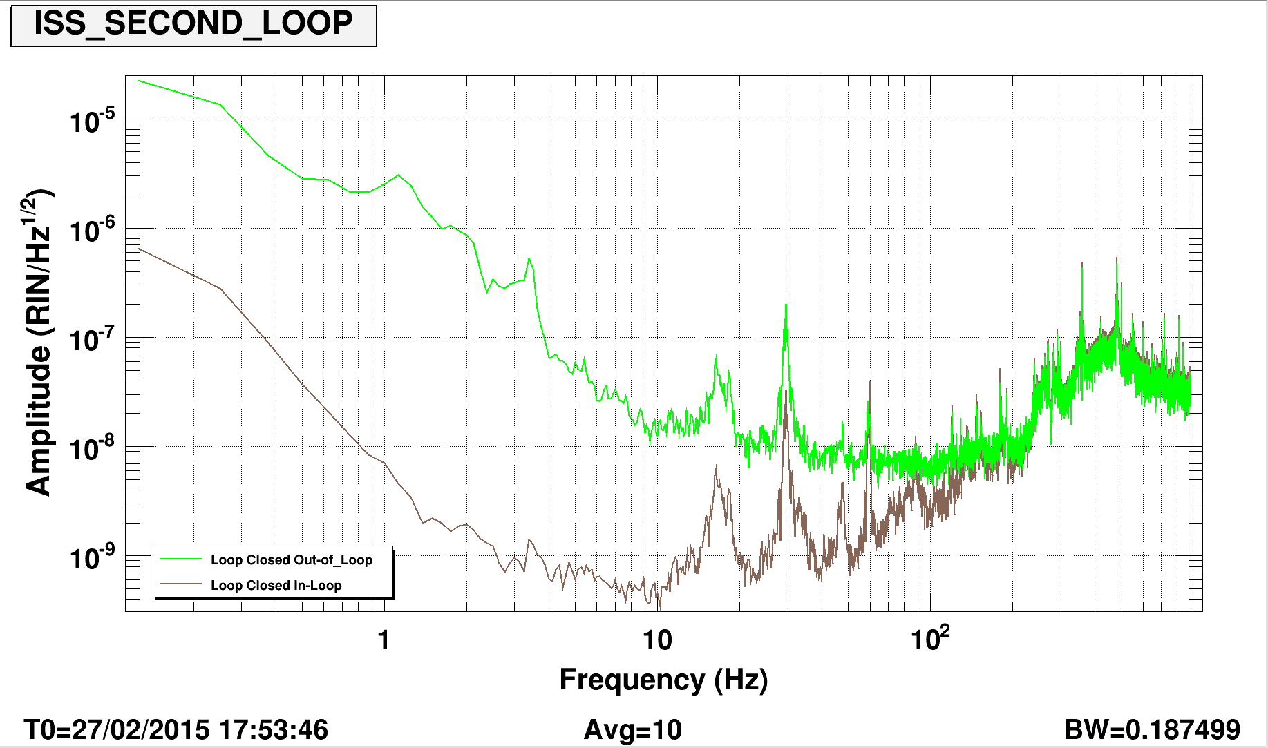
The in-loop and out-of-loop RPN measurement with the loop closed, gain set at maximum, boost and integrator engaged is attached below. The loop performance looks on-par with our past measurements, about 1E-8 at 10Hz.
Two modifications were implemented in the board:
In this way we can acquire the lock of the ISS second loop with in total 20 dB less gain than before. This solved our old problem of a second loop correction railing just before engagement of the loop. Now we can simply turn on the loop with -11 dB of global gain, then engage the +20dB stage and increase the gain to the maximum +31 dB.
The ISS lock acquisition is much simpler and much more robust than before.
For some reason these were not reconnecting, so I removed and readded them. They reconnected immediately after.

H1:GRD-IMC_LOCK_LOGLEVEL
H1:GRD-IMC_LOCK_MODE
H1:GRD-IMC_LOCK_NOMINAL_S
H1:GRD-IMC_LOCK_REQUEST
H1:GRD-IMC_LOCK_REQUEST_S
H1:GRD-IMC_LOCK_STATE_S
H1:GRD-IMC_LOCK_STATUS
H1:GRD-IMC_LOCK_TARGET_S
HAM1 ion pump pumping in parallel with turbo pump for the time being -> My plan is to demonstrate that the ion pump can pump solo for 2 hours at the current pressure (3.5 x 10⁻⁶ torr) then to consult with Daniel S. about the cost/benefit of the various options for the weekend
The days of the 08:30 meeting will change to Monday, Tuesday, and Thursday. No change to the start time. This is being done to coordinate the various 3IFO and maintenance activates with the needs of the commissioning team.

The normal Tuesday 08:00 to 12:00 maintenance window will remain, with no changes at this time.

Seismic – Closed the position loops on HAM1. HAM1 HEPI is unlocked. Hugh is working on grounding/noise issues with HEPI pump controller at End-X.

Suspensions – Running transfer functions for acceptance review. General 3IFO work.

IO – Dave & Elli are working on taking SRC measurements.

OpLev – Stuart and Jason are B&K testing the ITM-Y OpLev pier.

Vacuum – HAM1 is on the turbo pump. The HAM1 ion pump is being commissioned.
Sheila, Kiwamu,
Yesterday, Keita suggested us looking for any obvious sign of clipping in the ISCTEX table or some TMS mirrors (alog 16923) just by eyes (of course with goggles). So, we went to the end X station and inspected various places.
There was one mirror which showed quite bright scattering. We think that this is the one clipping the green light.
If we are lucky, maneuvering the angles of TMS and input PZTs may be able to fix the issue. Otherwise this potentially would be one of the tasks for the next vent.
The pictures of the TMX mirrors can be found in ResourceSpace (https://ligoimages.mit.edu/?c=1568)
(Details)
We started from the optics on the table. We did not find a bright scattering although there were many dim scattering all over the place because it is green light. We fully opened up two irises that were in front of the HWS 2" mirror and the one after it just in case. Then we checked the mirrors on the periscope which were not easy to look at directly by eyes and sensor card. We used a camera to remotely peek these mirrors. The beam spot on each of these mirror looked fine and we did not see a bright scattering off of them.
We then tried looking for any bright mirrors on the transmission monitor table (TMS). We used a camera to peek the mirrors. According to the pictures we took, the first mirror on TMS (M8 in D1201457-v2) showed a bright scattering off of it. It is hard to say where exactly the incident beam hits, but it seems that the beam is too low. On the other hand, it is not easy to tell about the horizontal off-centering. Note that since there was a risk of accidentally block the beam and trip the PZT pointing control, we disabled the loops with the offsets held at the output. Also the ETM was miasligned at this momenet in order for Elli and Dave to do the signal-recycled Michelson test. The way we identified M8 is that we could see another mirror closely behind M8, which we think is M9. Also some pictures showed another mirror far left from M8 and we think it is M10 as the mirror holder is mounted in a opposite direction. Also, some pictures showed another bright spot which is a known scattering point from the vacuum view port.
Summary:
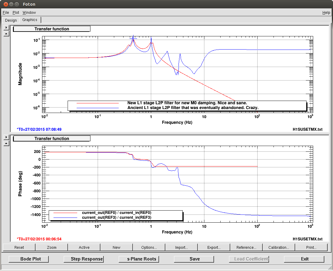
Somebody asked for a better L2P from ETMX L1 stage, so I made an attempt at making one.
With new top mass damping that was described in alog 16895 without OL damping, the measurement was done, filter was made, nothing was tricky, no hand tuning, no nonsense unstable poles, it just works.
But of course when OL damping is on, this nice L2P decoupling is broken (because the nice thing was made without OL damping).
I can probably make similarly nice decoupling filter for when the OL damping is on, but the question is exactly when such nice decoupling is necessary. OL damping on? Off? Both?
The ETMX is left with old configuration.
Details:
EX L1 drivealign L2L to oplev P, and drivealign L2P to oplev P were measured, and the latter was divided by the former. In both of these measurements, uniform noise from 0.1 to 1Hz was used and the amplitude was set so each coil outputs several thousands counts or so.
The resulting inversion function between 0.1 and 1.14Hz was fitted using happyvectfit, discarding any bad coherence data. No tuning was done except for selecting the measurement data and setting the fit order to 8.
The resulting L2P filter looks much nicer, Qs are lower, and in general it makes sense more than the ancient filter that was eventually abandoned (first attachment).
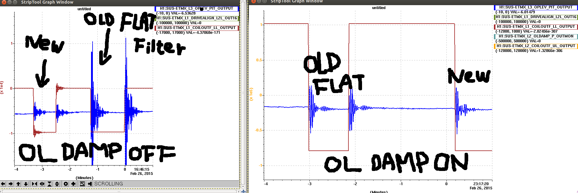
The second attachment shows the step response of ETM oplev (blue) when a large length drive is applied to the L1 stage (brown).
Left panel shows that the step response was about an order of magnitude smaller with the new L2P filter than the old flat gain filter that is used these days.
Right panel shows that when the OL damp is on, this nice reduction is gone, both the flat filter and the new filter are about the same, they are larger than "new" in the left panel.
Note that I had to make a new oldamp filter for this, as the old OLdamp filter is incompatible with the new M0 pit damping.
If you want to use the new settings:
Turn off the OL damping.
For M0 P damping, change H1:SUS-ETMX_M0_DAMP_P_GAIN from -1 to 0, turn off H1:SUS-ETMX_M0_DAMP_P FM2, turn on FM1, and set the gain to -3. This switches the M0 damping to more aggressive one.
For L1 drivealign L2P decoupling, change H1:SUS-ETMX_L1_DRIVEALIGN_L2P_GAIN from 5.3 to 1, turn off FM10, turn on FM3.
If you want to enable OL P damping, change H1:SUS-ETMX_L2_OLDAMP_P_GAIN from -6500 to 0, turn off FM10, turn on FM9, then set the gain to -4500.
The new OL damping for the new M0 damping is far from good, but it's stable.
The following nodes have reported the epicsMutex thread error:
epicsMutex pthread_mutex_unlock failed: error Invalid argument
epicsMutexOsdUnlockThread _main_ (0x2999f20) can't proceed, suspending.
node and log file:
ISI_ITMX_ST2/@4000000054e3b1f036d0862c.u
IMC_LOCK/@4000000054efab210f2ebddc.s
SUS_PRM/@4000000054eceebe32bce24c.u
SUS_ETMY/@4000000054eceebe20a258e4.u
Still unclear why this is happening. It happened most recently on IMC_LOCK yesterday, and the first known incident was with ISI_ITMX_ST2 on February 16, while I was testing the new guardian release before the upgrade.
Jim, Dave
We have installed 10 Apple Magsafe2 power adapters in the control room on the Magsafe power cords. To hopefully prevent these from wandering or getting lost, we followed Rana's advice and purchased MagCozy tethers for these, please see attached photographs.
A reminder, please do not use the magsafe cable which is bundled in the iMac to Thunderbolt Monitor cables. This cable is not long enough to use without pulling on the display port cable which has lead to breakages in the past. If we need more Apple power cords in the control room, please contact me and I will purchase some more.


👍
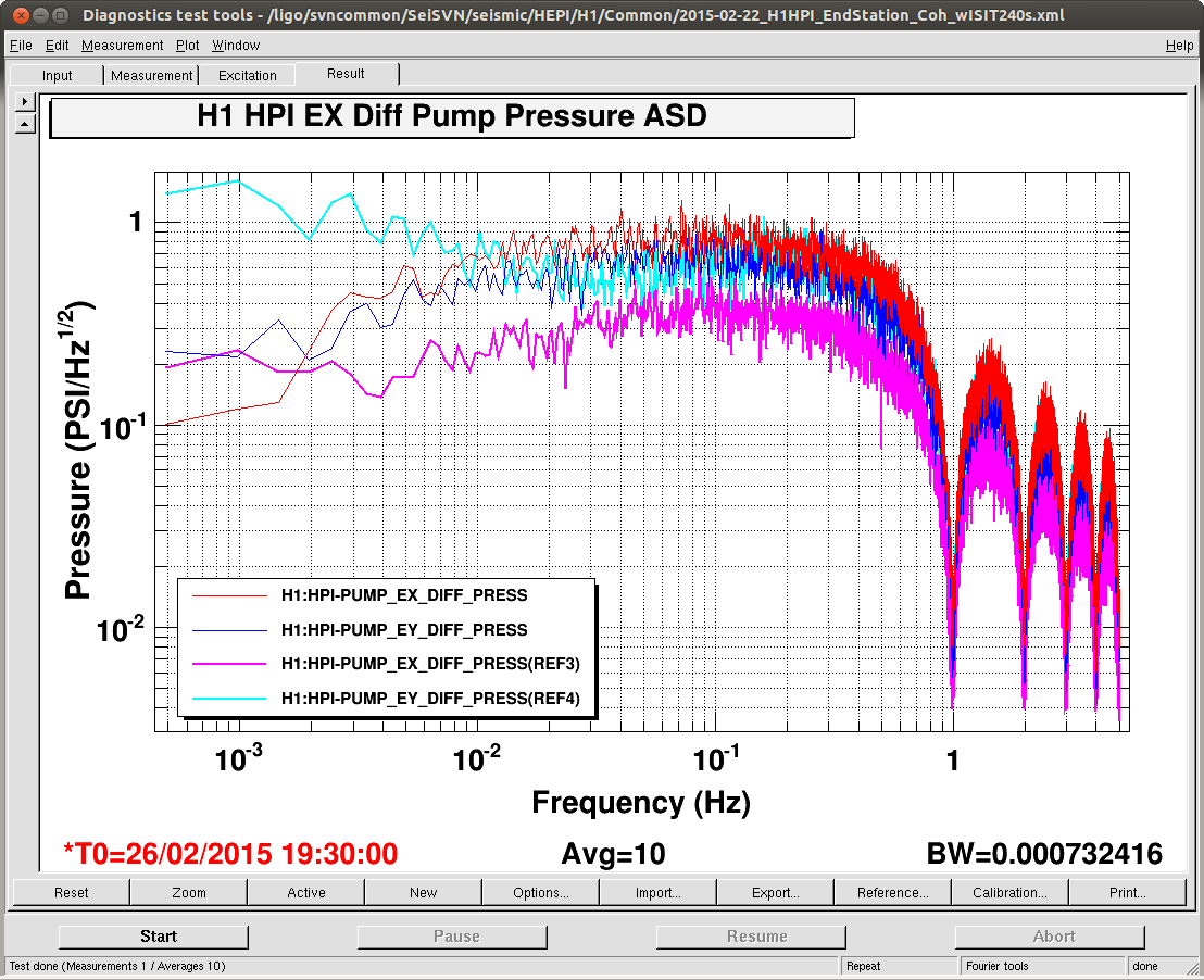
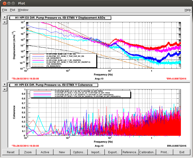
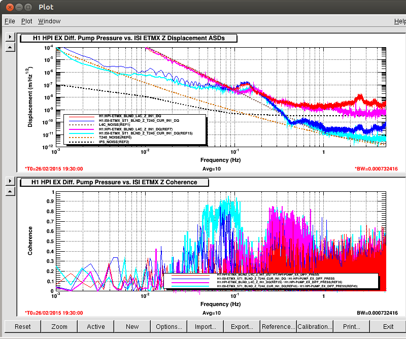
Well, unlike at EndY, the pump station maintenance did not pay off as well. Bottom line: remaining coherences seen in the Z and HP dofs are not reduced as much as they are at EndY after the maintenance. Possible reason--while I found lots of Accumulators that needed charging (just like at EndY,) the explicit grounding of the power supply common legs did not make the Pressure Sensing noise better. In fact something in this process has made the sensor noise worse; but it was't the adding of the ground.
Details: First I added the explicit jumper from the common legs on the power supply to the supply ground plug but this had no observable affect on the striptool I was watching. I figured it was doing no harm. After Guardian brought ISI/HPI down to OFFLINE, I ramped the pressure down with the servo. Then the motor was greased and Accumulators were charged: most Accumulator were essentially uncharged and two on the pump station were leaking. I was able to play with the Schaeder Valve and stop the leaks (may be iffy.) After the Accumulators were charged, the system was brought back online and Guardian reisolated with no problems.
See the first attachment for the second trends where the system was down and then back on. This is where I first saw that the noise on the pressure sensor channel more than doubled. What happened to cause the noise to change like this? I plugged the ground wire in before bring the pump down and didn't see an noise increase. Is the power supply flaky? I did have to move the servo box around to access the Accumulators...
It is clear this is bad when you look at the second attachment with the Pump Pressure ASD: it is a few to several factors worse than Sunday(Reference traces.) The remaining attachments are the coherences between the Pump Pressure and the HEPI L4C & ISI T240s. The coherences have improved suggesting the Accumulator serve us well. But the improvements are not as good as seen at EndY where the Pump Pressure Noise dropped 5 to x10.
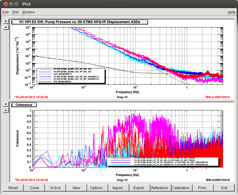
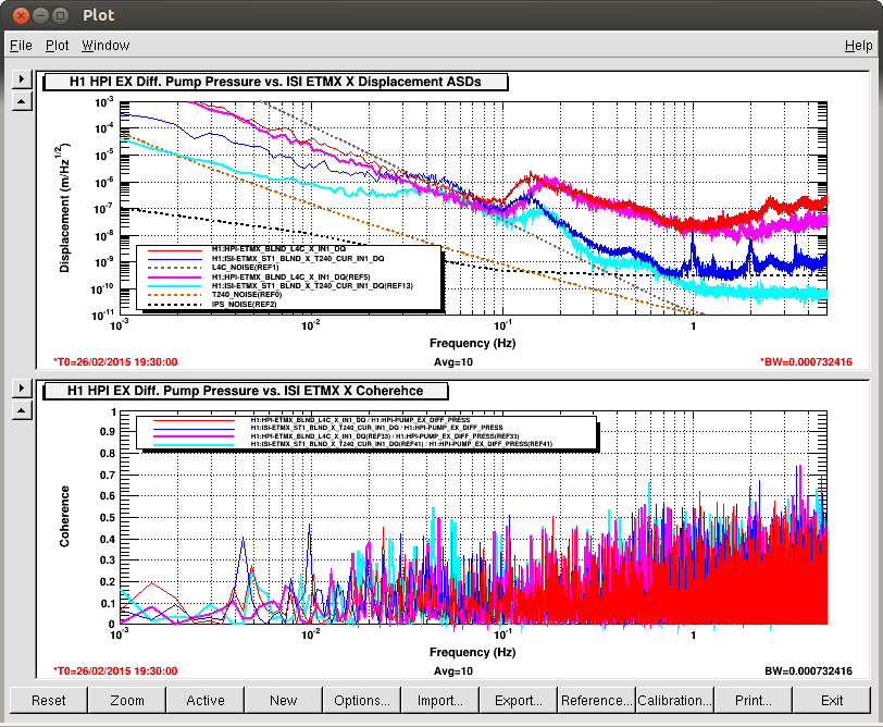
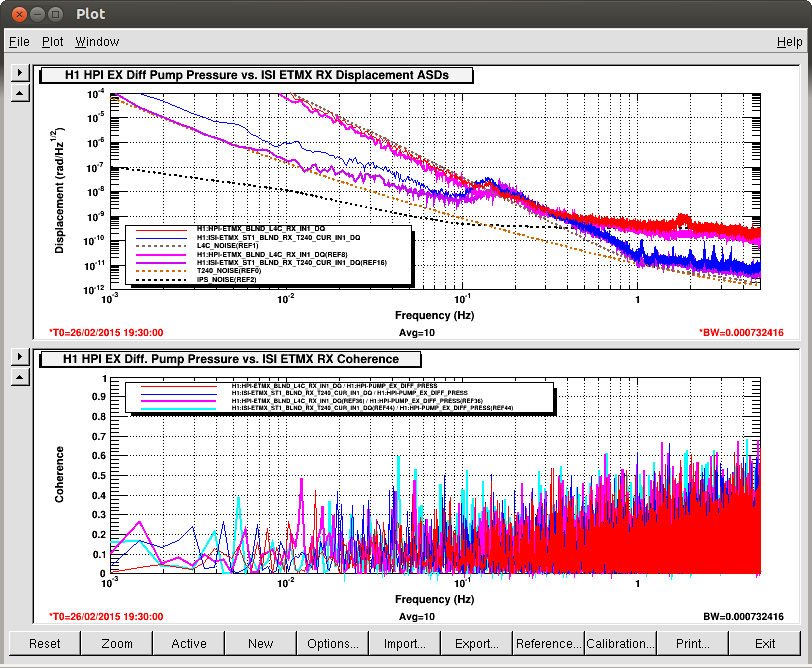
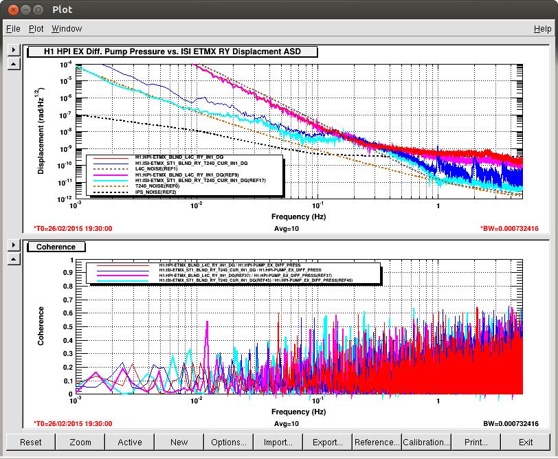
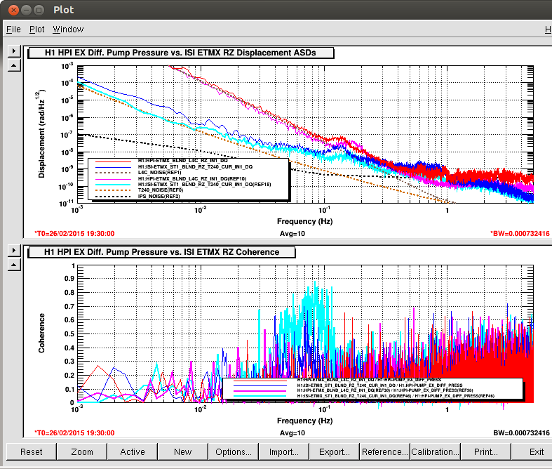
It is clear even from the thumbnail that the RZ had some coherence as well but is too now reduced with the Accumulator charging. The RZ didn't have near this much coherence at EndY.
This morning, Stuart and I used the SDF front end to take new SAFE.SNAP snapshots of the balance of the suspensions - recall, he had done the BS previously, see alog 16896.
Repeating his alog instructions on how to perform this:
- Transition the Suspension to a SAFE state via Guardian
- On the SDF_RESTORE MEDM screen available via the Suspension GDS_TP screen select FILE TYPE as "EPICS DB AS SDF" & FILE OPTIONS as "OVERWRITE" then click "SDF SAVE FILE" button to push a SDF snap shot to the target area (which is soft-linked to userapps).
- This safe SDF snapshot was then checked into the userapps svn:
/opt/rtcds/userapps/release/sus/h1/burtfiles/
M        h1susbs_safe.snap
Note, please don't use the BURT interface to take SAFE.SNAP snapshots anymore, as the SDF monitoring will become disabled. All other snapshots are free to be taken via BURT, however.
Also, we found many alignment values not saved on IFO_ALIGN which, after confirming with commiss, we saved.
[Betsy W, Stuart A, Jamie R]

After taking safe SDF snapshots for the IM Suspensions, we found that Guardian had crashed for the IM2 and IM3 when we had attempted to transition them from SAFE to ALIGNED states. Oddly IM1 and IM4 still transitioned fine.

Upon checking the Guardian log it was apparent it was falling over for IM2 & IM3 immediately after reading the alignments from the *.snap files. Under initial inspection there was nothing obviously different or wrong with the IM2 & IM3 alignment files.

After contacting Jamie, he noticed an extra carriage return at the end of the IM2 & IM3 alignment files, which was causing issues for Guardian. Removal of the carriage return, and reloading Guardian rectified the problem.
To be clear, the IM2/3 guardian nodes hadn't crashed, they had just gone into ERROR because of the snap file parsing issue.
Also to be clear, there is a bug in the ezca.burtwb() method, which is being used to restore the alignment offsets, such that it doesn't properly ignore blank lines. This will be fixed.
Unclear why these alignment snap files had these extra blanklines. My guess is that they were hand edited at some point.
Above, when I said "Note, please don't use the BURT interface to take SAFE.SNAP snapshots anymore, as the SDF monitoring will become disabled. All other snapshots are free to be taken via BURT, however."
I was just speaking to SUS safe.snaps. Sorry for the confusion.
I am concluding that the scale factor in the original calibration (alog 16698) was underestimated by a factor of about 2.4 in 2 - 20 Hz frequency band (meaning, the DARM spectra we had collected were too good). This was due to my inaccurate estimation of the ESD actuation response.
For the frequency region above 20 Hz, it has been underestimated by a factor of 3.2 when the PSL power stayed at 2.8 W and the same DARM offset was used. This was due to the inaccuracy in the ESD propagating into the sensing factor and also inaccuracy in the UGF location. I did not try to track how the sensing calibration should have been compensated as a function of the PSL power or the DARM offset (alog 16726).
I have updated the CAL-CS online calibration coefficients accordingly in both the sensing and actuation paths.
Pcal_Y seems to still indicate that the DARM spectrum is consistently too good by 40-65 %.
(ETMX response agreed the sus model by 40 %)
The day before yesterday, I had a chance to repeat the calibration of the ESD response of ETMX by locking the X arm with the IR laser. Comparison with ITMX at 13 Hz gave me an ESD response of 6.32 x 10⁻¹⁶ m/cnts in ETMX at 13 Hz. This is 1.4 times larger than the expected than the suspension model. Since I used alpha of 2.0 x10⁻¹⁰ N/V2 in the model, the measured response corresponds to a slightly larger alpha of 2.8x10⁻¹⁰ N/V2. With the right force coefficient of -124518.4 cnts applied on ETMX, I tested both the linearized actuation and non-linearized. They showed almost same strength in a frequency band of 10 - 59 Hz as expected but with the linearized version somewhat stronger by 3-ish % (see the attached) presumably due to the charge on the test mass.
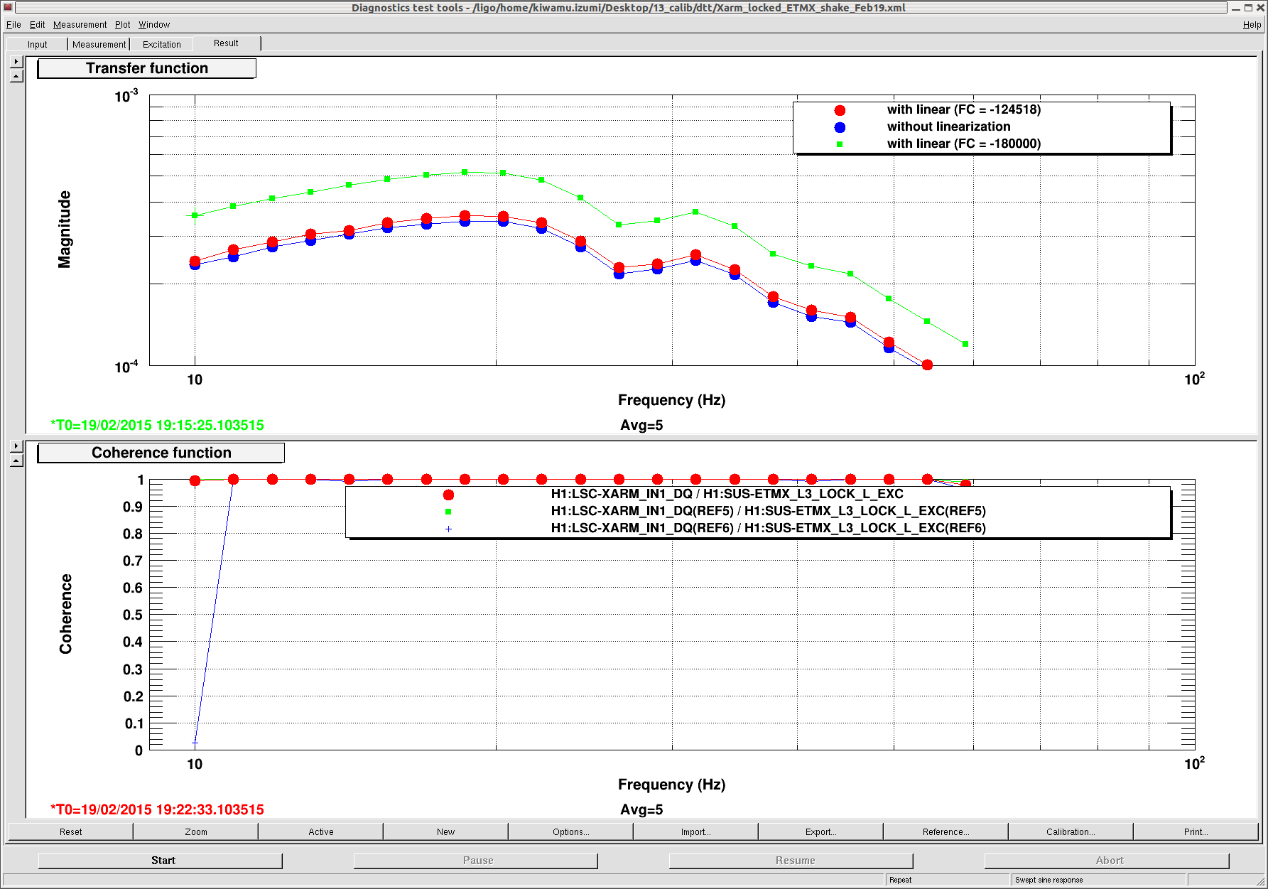
Since the change between the linearized and non-linerized actuations is so small, I neglected this effect and kept using the transfer coefficient of the non-linarized version at 13 Hz.
(Estimation of the DARM optical gain)
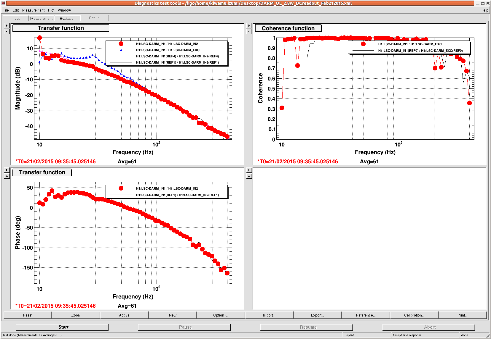
Using the measured data taken by Alexa (alog 16805), I estimated the optical gain of the DC read out to be 9.09x10⁻⁷ cnts/m. To get this number, I first extrapolated the ESD response to some frequencies at around 20 Hz. Since the loop shape is already known, fitting of the open loop gives me the optical gain. I did eye-fitting this time. The UGF was at around 23 Hz in this particular data.
Since I was able to lock the interferometer at 2.8 W with the DC read out tonight, I cross-checked the DARM open loop. Running a swept sine, I confirmed that it sill kept the same UGF (see the attached below). Good.
(Comparison with Pcal)
First of all, one thing I have to mention is that, in an alog (alog 16781) describing the comparison between LSC-DARM_IN1 and PCAL is not a fair comparison because we know that LSC_DARM_IN1 was not well-calibrated. I checked the CAL-DELTAL_EXTERNAL_DQ at this particular time, but unfortunately the spectrum did not look reasonable probably because I was in the middle of changing some parameters in the CAL-CS. Instead, I looked into a different lock stretch at Feb-02, 5:13:11 UTC with the same IMC incident power of 2.8 W. The Pcal reported greater displacement by a factor of approximately 4.6 (see the attached below).
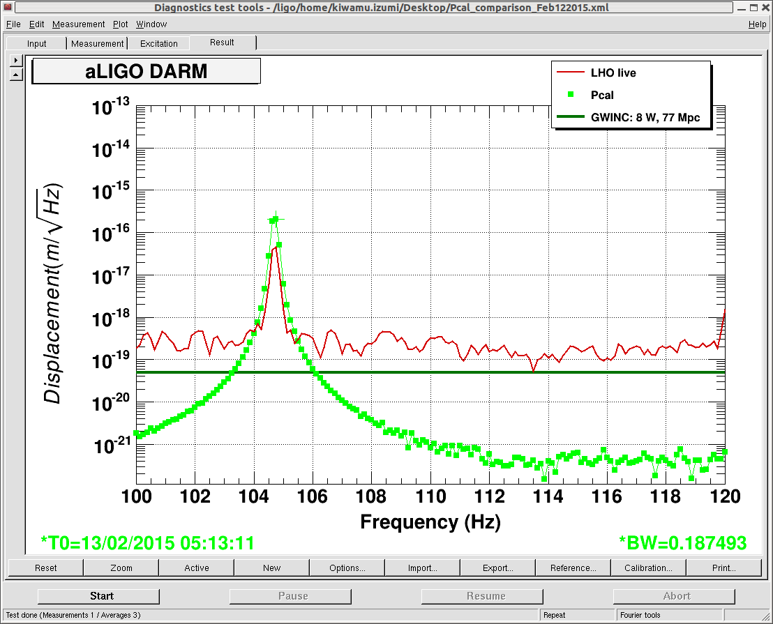
If I applied the new accurate sensing calibration, the discrepancy would have been a factor of 1.45 or 45% with the Pcal higher than the DARM spectrum.
To double check it, I checked the Pcal again during one of today's lock stretches at Feb-21, 10:04:05 UTC. One thing we have to pay attention is that the Pcal excitation frequency is now shifted to 540.7 Hz (alog 16815). I used the Pcal calibration formula that Sudartian posted in alog 16718 to get the displacement. The ratio between the Pcal and DARM spectrum was about 1.65 or 65% with the Pcal greater than the DARM spectrum. Even though the ratio is slightly different from 8 days ago or so, it still indicates that the DARM calibration is too good by several 10%.
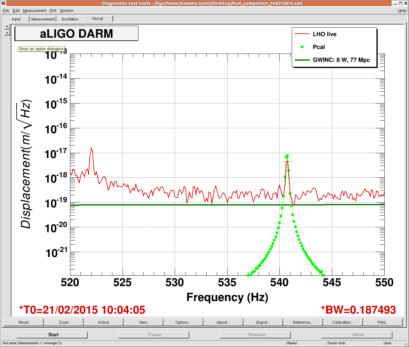
The other excitation at 36.7 Hz (alog 16815) did not have signal-to-noise ratio more than 2 in the DARM spectrum due to high noise in this frequency region and therefore I did not use it this time. Nevertheless, the Pcal at this frequency was also greater as well. So the relation between Pcal and DARM spectrum is qualitatively consistent.
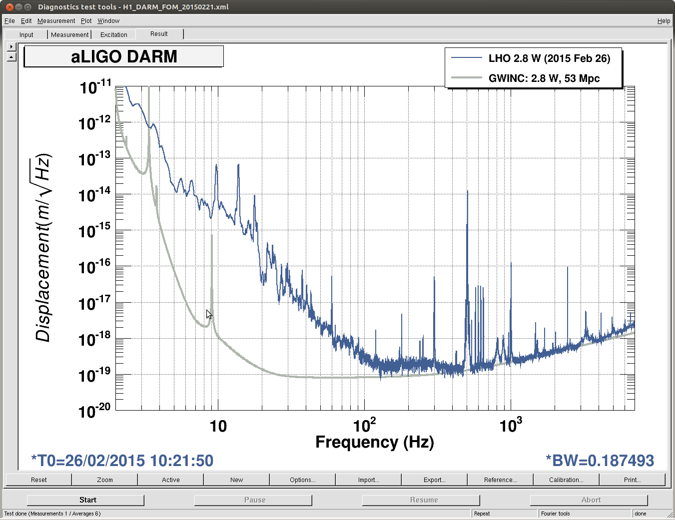
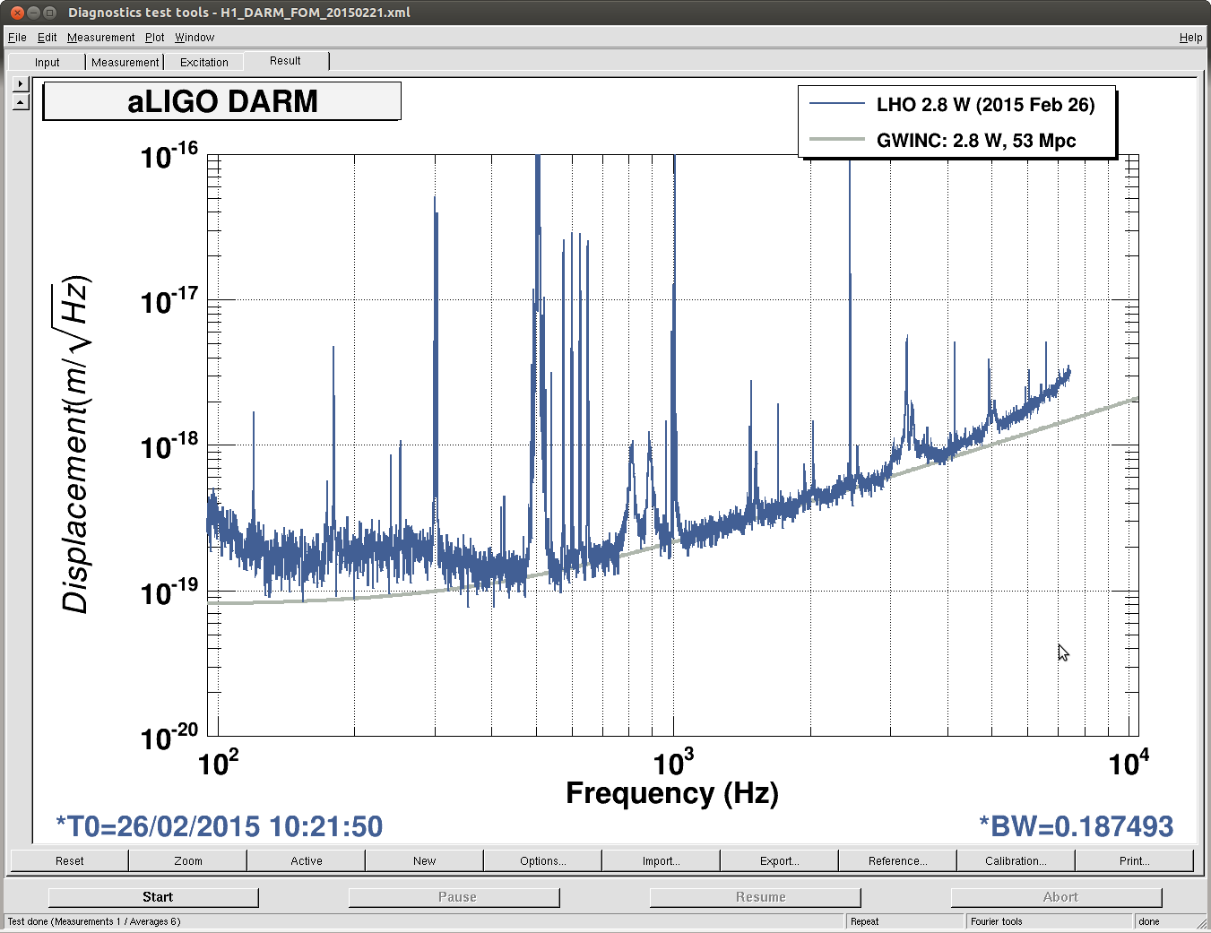
Here is a fresh DARM spectrum (from 2015-02-26 10:21:50 UTC) compared with the GWINC prediction. Between 1 and 3 kHz (where the spectrum looks reasonably clean and has the right shape for shot noise), the agreement looks good.
GWINC reports 9 Mpc from this measurement.
This is another detail point of this calibration log (for my self-justification).
In the ISC call last Friday, people pointed out that the first Pcal plot (link to the plot ) seemed greater by a factor of 10-ish than the calibrated DARM. Here, I explain that they don't differ by a factor of 10 but a factor of 4.6 as I declared in the original alog.
To be celar, I attach a zoomed version of the previous plot. See below.
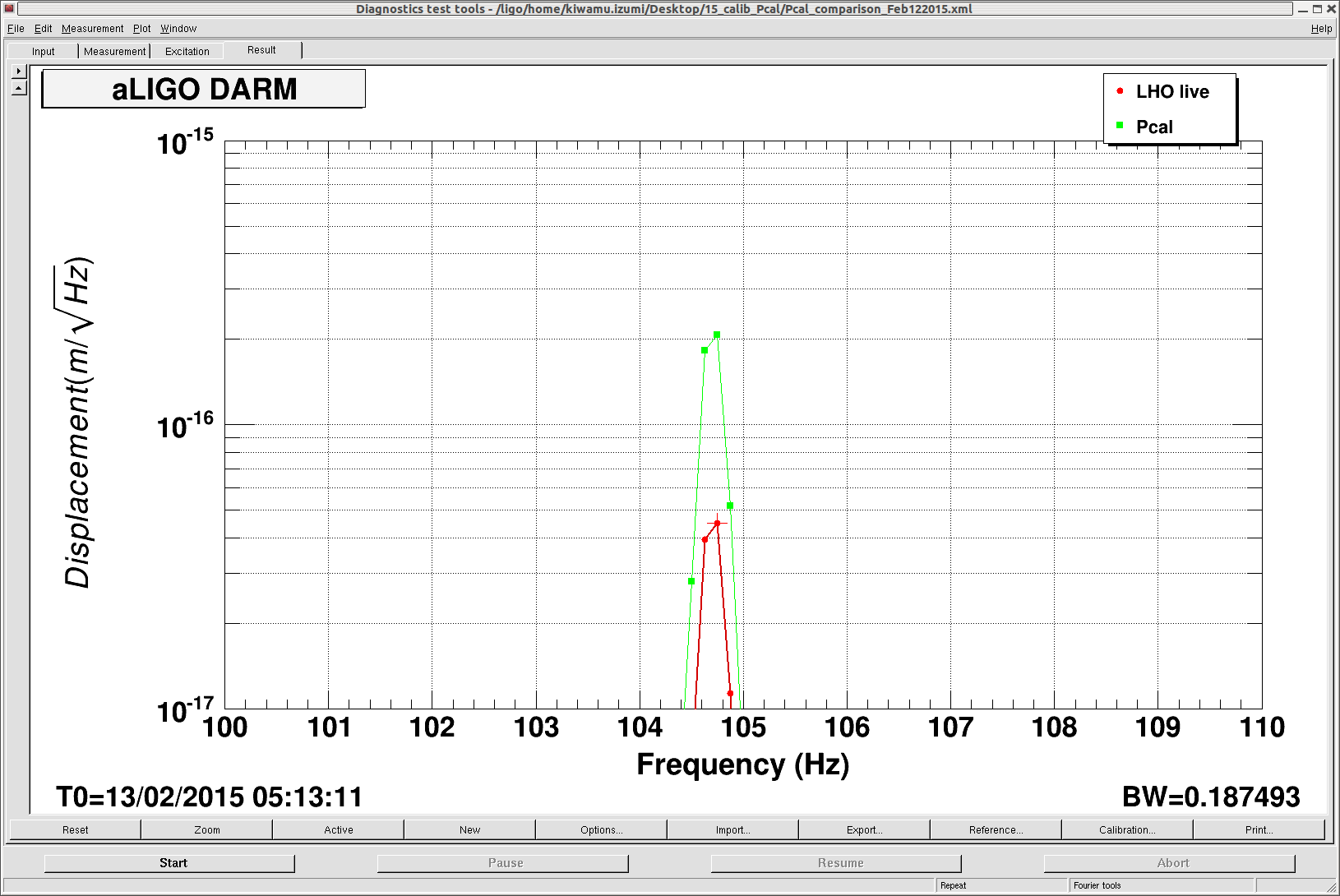
Taking the ratio of Pcal/DARM, I again confrimed that the ratio is 4.6185. This is the number I quoted in the original alog. Here, I repeat a conclusion I said in the original alog: since we now know that the DARM calibration was off by a factor of 3.18 on Feb 12th, if we apply this correction the descrepancy between Pcal and DARM would have been a factor of 1.45 or 45 % with the Pcal greater.

