betsy.weaver@LIGO.ORG - posted 12:34, Wednesday 25 February 2015 (16918)
empty filters requested ON
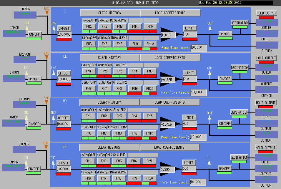
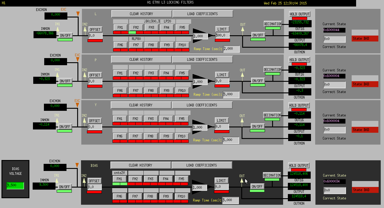
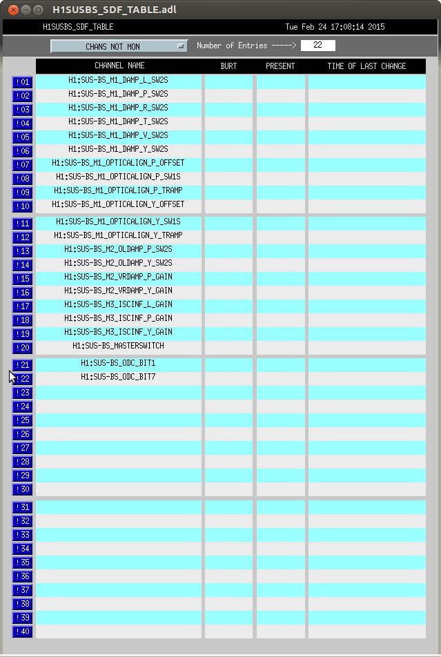
While Stuart and I were looking at SDF and GRD monitoring, we noticed that there were some empty filters that were requested to be on, but were not on. I've turned them off. Attached are the 2 screens where I found such benign filters in the half-state (ETMX L3 LOCK, and BS M2 COIL). They are off now. We intend to get new safe.snaps tomorrow so likely any remaining leftover empty filtering will be cleared out.
Images attached to this report