Stefan, ThomasV, Kiwamu,
Tonight we continued working on the BS high bandwidth loops (see previous alog 15662). We successfully engaged both pitch and yaw loops with unconditionally stable 1/f open loop shapes.
We also worked on PR3 loop a bit as well.
(BS high bandwidth loops)
Even though we had success yesterday on the BS loop, we were not satisfied with the loop shape as there was multiple UGFs. Today we tried inverting the BS M2 stage plant so that we can nicely have a 1/f open-loop shape. We studied the plant inversion using the oplev damping paths at the beginning and PRMI. Later on we applied the resultant inversion plant in the actual DRMI ASC loops. Here are the inversion filters we used as a starting point:
-
BS M2 P to P = zpk([ 0.013 + i * 0.485; c.c.; 0.0183333 + i * 1.112; c.c.], [], 1)
-
BS M2 Y to Y = zpk([ 0.2 + i* 0.45; c.c.; 0.022 + i * 2.19; c.c. ] [], 1)
Note that the lower resonance in Y-to-Y has a mismatch both frequency and Q. With these inversion plant filters in, we then modified the location of the resonances as well as their Qs of the inversion filters as we observed instability in the loops. In particular, we tended to slightly lower the resonant frequencies and Qs such that the phase of the open-loops go up in order to prevent them from small phase margin. The actual resultant inversion filters are written in the foton files.
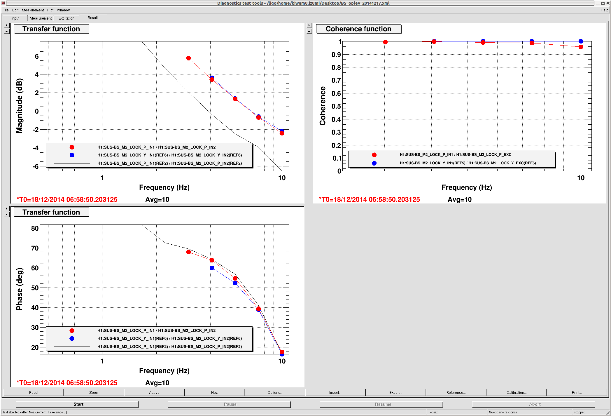
We did a simple in PRMI where we ramped up the overall gain of two loops from 0 to the nominal in a minute to see if there is unstable region. As expected, we did not see instability at all. So the loop is unconditionally stable with opelv damping loops off. Then we applied the new inversion fitter in DRMI with the new AS_Q input matrix. This went pretty smooth. The attached is the nominal open loop transfer functions for both pitch and yaw. They are currently set to 7 Hz. The whole setup is coded in guardian. ISC_DRMI.
(PR3 ASC loops)
We briefly closed the PR3 ASC loops using REFL_B9_I. There was large coherence between the power build-up and PR3 angular motion. For now we made a low bandwidth loop, but tomorrow we should commission a high bandwidth loop as there was fast residual angular motion.
(Pointing DOF)
We also quickly checked if the POP QPDs are sensitive to a pointing DOF. We moved IM4 and let PRM and PR3 follow the IM4 pointing to see if we can see it on the POP QPDs. And we confirmed that_POP_B QPD was sensitive to the pointing DOF.
(Some guardian update for SRC2 loops)
The setup for the SRC1 and SRC2 loops are now coded in the guardian as well. This is something reported in alog 15638,


This switch was removed in favour of another trigger switch at LLO. I believe the related alog to this change is this LLO alog 10933 by David F