The two uncontrolled degrees of freedom in the mode cleaner ( MC1 - MC3 in pitch and MC1 + MC3 in yaw) are now under control. These two degrees of freedom result in motion of beam spots on the ASC_IMC WFS sensors. The beam spot on the WFS_B_DC sensor is now controlled with the DOF_4 servo loop in the ASC_IMC model.
This scheme avoids two potential problems which could arise if we use IM4_TRANS as the sensor of choice for controlling these two degrees of freedom.
a) IM4 TRANS QPD is affected by the longterm drifts of IM1,2 and 3. We would be folding these drifts back into IMC alignment if we use this sensor.
b) These drifts could further result in a drift of the spots on the WFS (since this is not a controlled parameter) and that could generate RIN due to spurious offsets in RF WFS signals.
During the course of this work I have made the following changes:
1) Offloaded the servo loop outputs using the Offload_WFS script
2) unlocked the mode cleaner and misaligned the MC2_PIT (to prevent flashing of the IMC)
3) centered the prompt reflection on the IMC WFS
4) realigned the MC2 and relocked the mode cleaner
5) the extinguished field landing on the IMC_WFS QPD generates a random offset due to the wierd pattern of the HOM. This was zeroed out using offsets in the WFS A and B, DC (PIT and YAW) sensors. (Had to fix some macro entries in medm screens of the PIT and YAW filter banks so that we can get at the offsets)
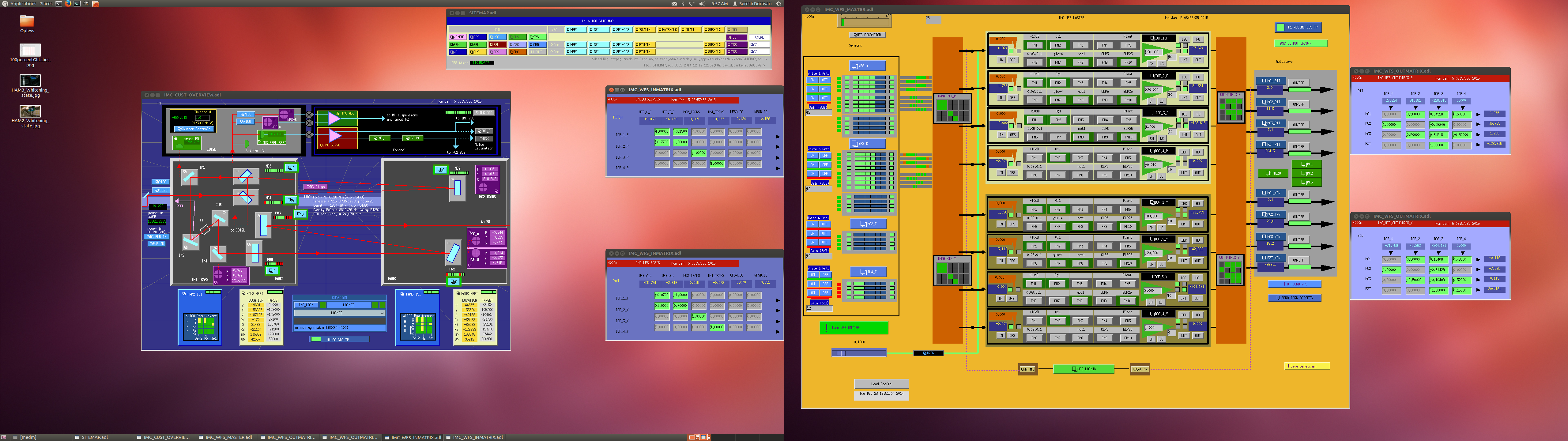
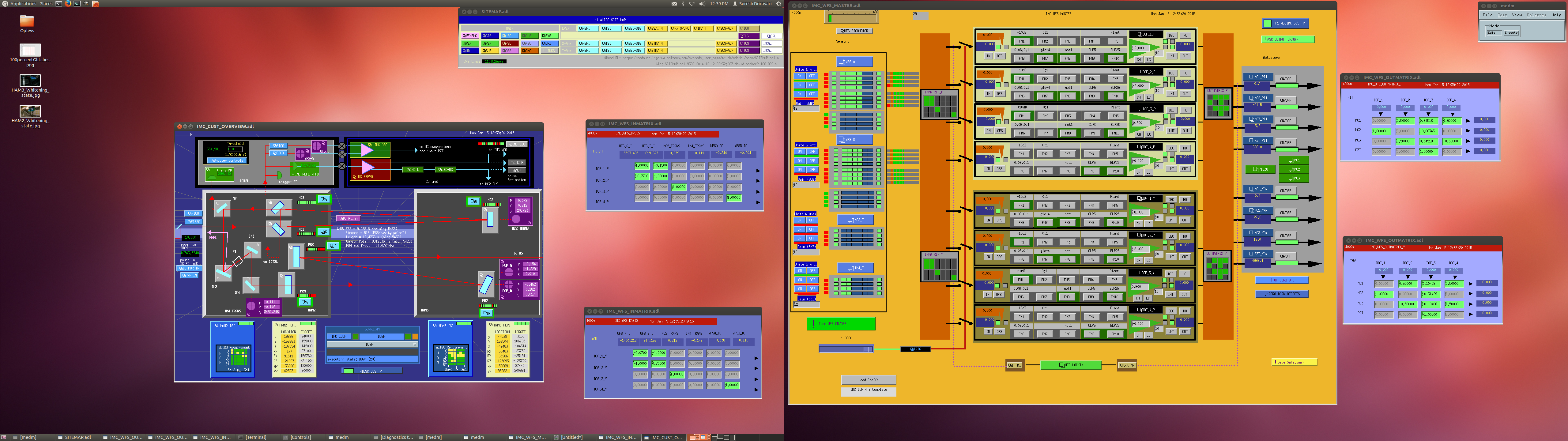
6) adjusted the output matrices to 0.5*(MC1-MC3) in Pitch and 0.5*(MC1+MC3) in Yaw. Attached screen shots show the situation before and after these changes to the input and output matrices.
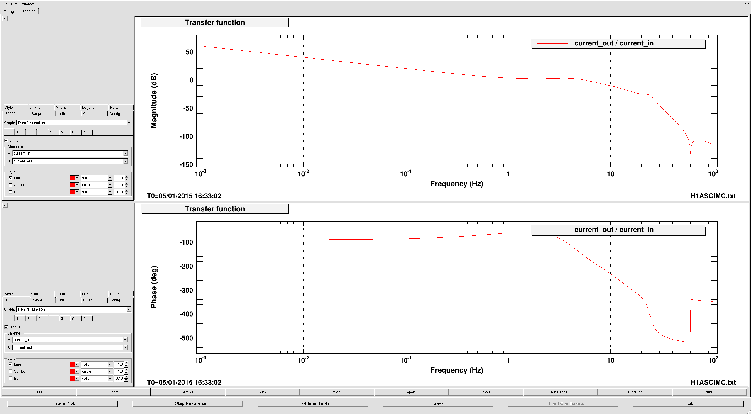
7) Checked the stability of the servos.
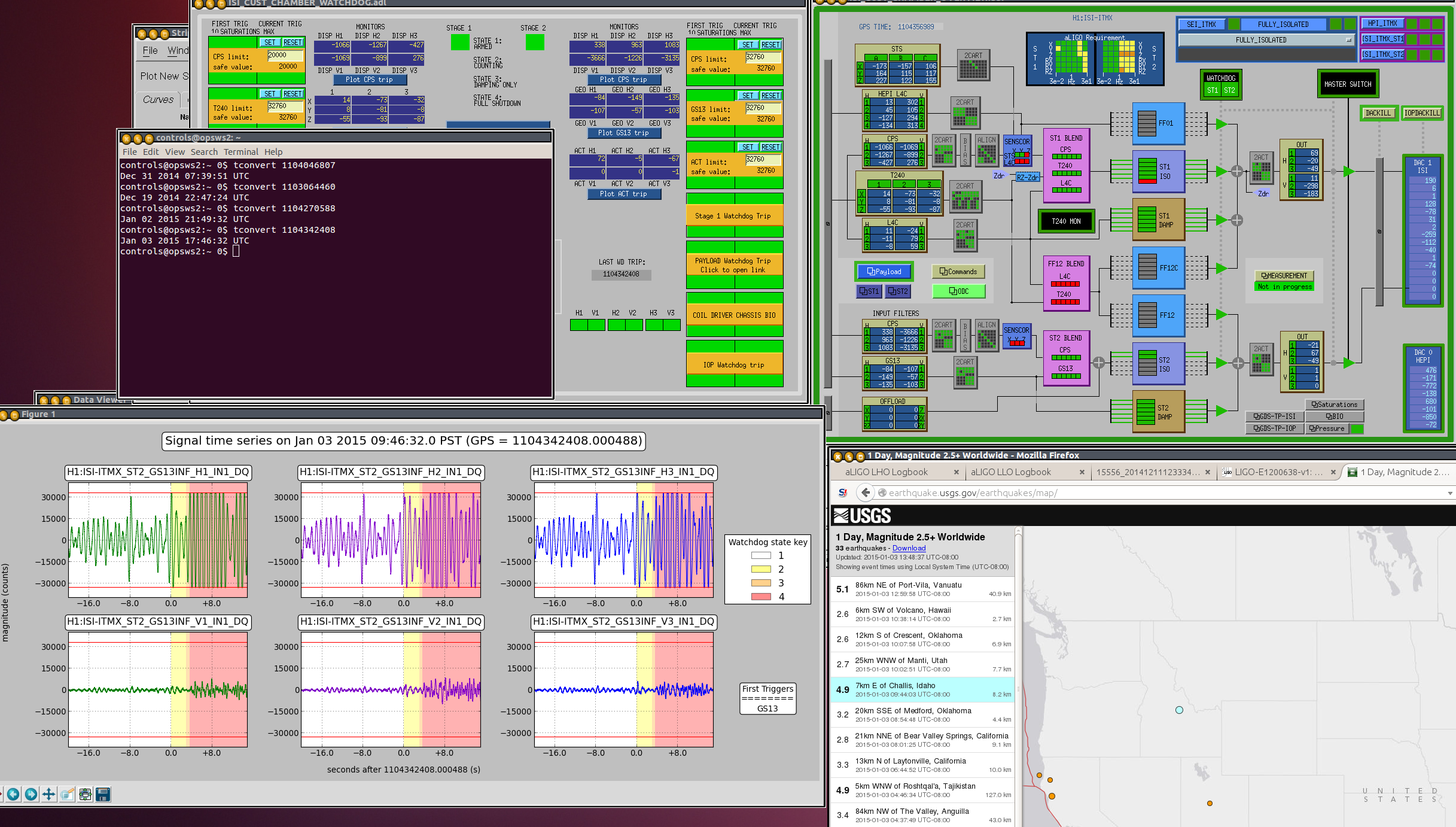
8) There has been no significant shift of the beam on pointing into the IFO as a result of this work. Attached pic shows the time trends of IM4_TRANS_PIT and YAW
9) The UGF of these loops is about 100 mHz (a factor three lower than other loops in the ASC_IMC)
10) Next I will look into determining the DC offsets which minimise the jitter to RIN coupling.
11) I have modified some of the indicators in WFS_MASTER medm screen so that the switching on and off of the servo loops by IMC Guardian is apparent on the screen.
Havent had a chance to see the effects of some of these changes since the mode cleaner has not been locking in the past couple of hours due to ongoing work in the PSL ref cavity alignment.