Jim, Dave: WP5003
This morning we upgraded H1 FE and DAQ to RCG2.9. First the DAQ was upgraded and restarted. Then FE startup scripts were changed, model startup scripts changed.
Then a "make installWorld" was ran to install the models which were compiled yesterday. The H1.ipc file generated yesterday was re-installed.
We tested a reboot-restart first on a non dolphin FE (h1susauxh2) and then on a Dolphin FE (h1seib1).
We then restarted all frontends in the MSR by power cycling the computers, and end station frontends by rebooting the computers. We ended up having to powercycle h1iscex because it got stuck in reboot. In the MSR when we were restart testing, h1susb123 got stuck on reboot and needed a power cycle which Dolphin crashed the other MSR machines.
We got to a stable system with DAQ and FE reboots proceding correctly. We had 6 front end IOP models with large IRIG-B excursions into the 1000-2000 counts. The h1oaf0 IOP took 4 hours to return to normal IRIG-B range. One IOP went below zero (999998) which caused IPC errors on models receiving its channels. This fixed itself in about 10 minutes.
We noticed a single ADC error on the h1ioplsc0, which was cleared with a DIAG_RESET.
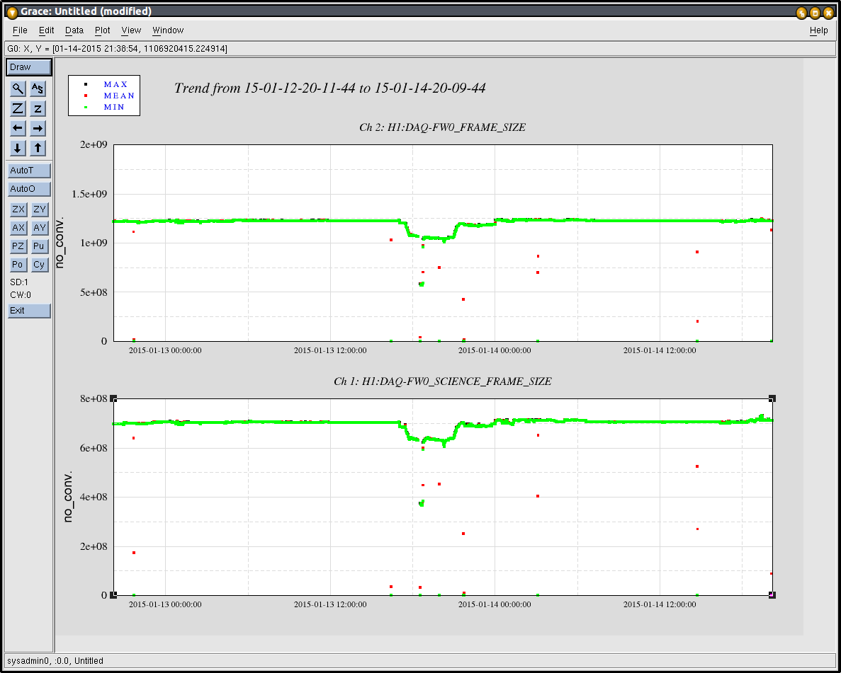
We noticed the DAQ frame size is smaller now. For science frames 670MB to 610MB (10% reduction) and commissioning frames 1.2GB to 1.0GB (20% reduction). We suspect new common models are the reason for this.
I linked Jamie's SDF_OVERVIEW MEDM screen to the SITEMAP under the GRD section. We are configuring the IOP, PEM and PSL systems.
This closes WP5003