J. Kissel, S. Biscans, D. Barker, J. Batch
*Sigh* there's always a fire. Today's fire was that just before Dave and Jim went at EX to swap ADC cards (see LHO aLOG 16023), they'd asked Seb to turn off SEI ETMX. Once they looked, they found that the IOP Software Watchdog had tripped on the SEI system.
In summary, there is a nasty but slow instability between the ST2 Y isolation loop and the QUAD T, RX, and RZ motion. We've never seen it before because we rarely, if ever, run the QUAD without damping and the ISI in fully isolated for more than an hour or so to take transfer functions. However, the independent software watchdog did exactly what it what it was supposed to do, and prevented extended shaking of the suspension caused by ISI instabilities. As Vern suggests, perhaps I awoke a daemon by jokingly invoking quotes from the Poltergeist last night, but it looks like we're well protected against daemon attacks.
Here's the story.
05:25 UTC - Jeff requests SEI_ETMX Manager guardian to go to Fully Isolated (Remember this configuration includes *no ST1 RZ isolation*, and *no ST2 Z, RX, RY, or RZ* see SEI aLOG 658)
05:28 UTC-5:35 UTC - Jeff takes transfer functions of SUS ETMX (see LHO aLOG 16012), and *leaves* M0 damping loops OFF.
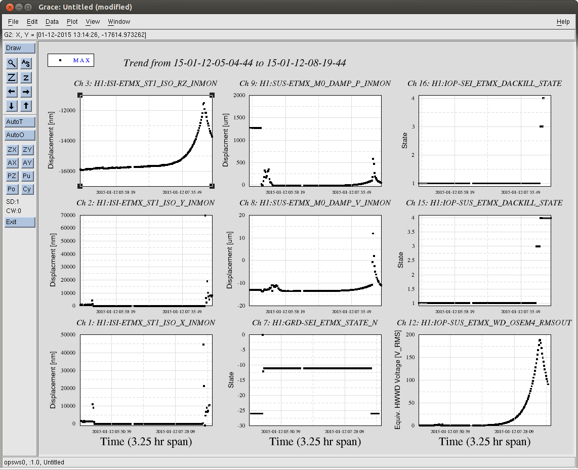
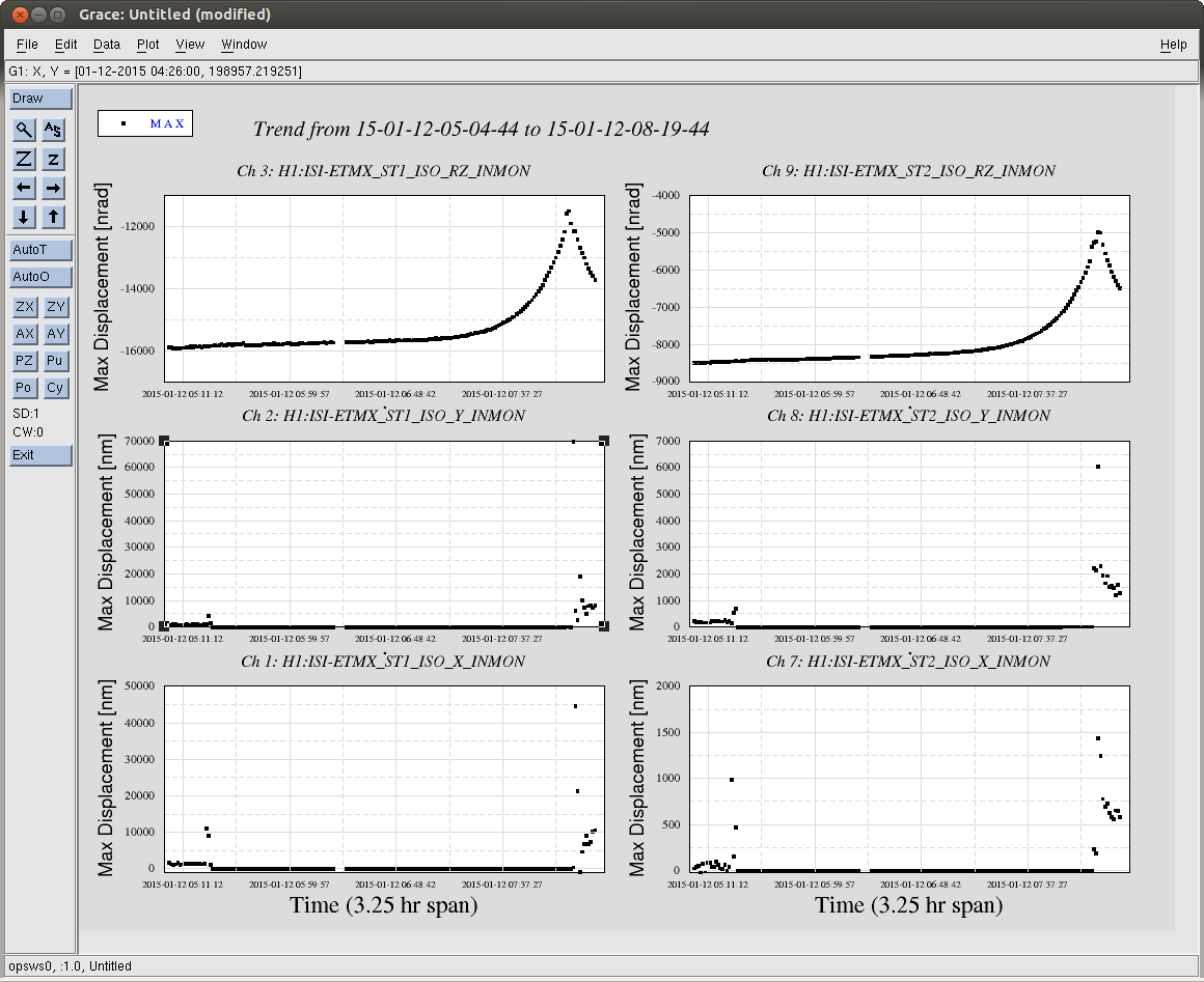
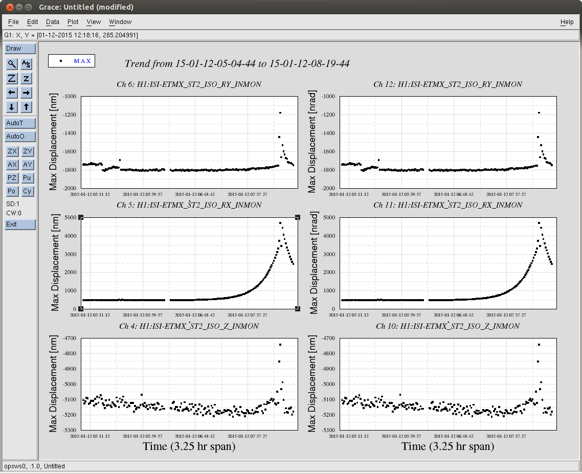
Over the next two+ hours, the maximum ISI ST2 Y RX RZ displacement begins to ring up, most prominently at exactly 0.46 [Hz], the first Transverse Mode of the QUAD's main chain. (Note that the first L Mode at 0.43 [Hz], the first R mode at 0.92 [Hz] are also rung up as well, but not at the same amplitude). There is some, very slow, parasitic, positive feedback cross coupling between the free ST1 ISI RZ, or ST2 Z, RX, RY, and/or RZ and the QUAD's first T / R mode that leaks into the ST2 ISI's Y DOF loop that *is* closed, and slowly but surely rings up the ST1/ST2 Y/RX/RZ motion, and eventually rings up the whole system into instability.
The QUAD's watchdogs DO NOT trip, because the M0 and L2 watchdog has been spuriously set to 80 000 [ct]. Even if they did, the SUS all actuation on the SUS is already OFF, so it would have made no difference. Only if ALL FOUR SUS USER watchdogs tripped (M0, R0, L1, and L2), would it have triggered the SUS USER DACKILL, and sent a "PAYLOAD BAD" flag to the ISI, tripping its USER watchdog.
However, the SUS Independent Software Watchdog (IOP watchdog or SWWD), which also watches the RMS of the Main Chain begins sees this increase in RMS.
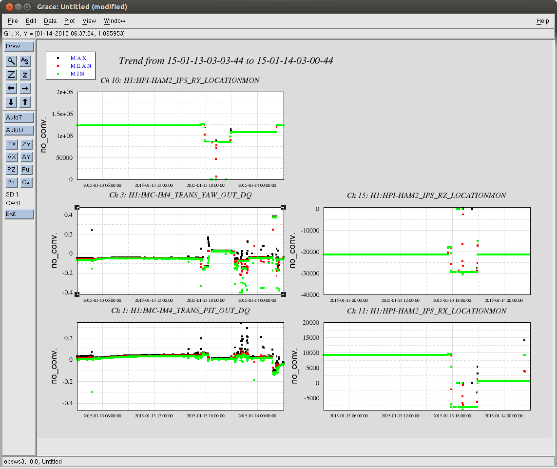
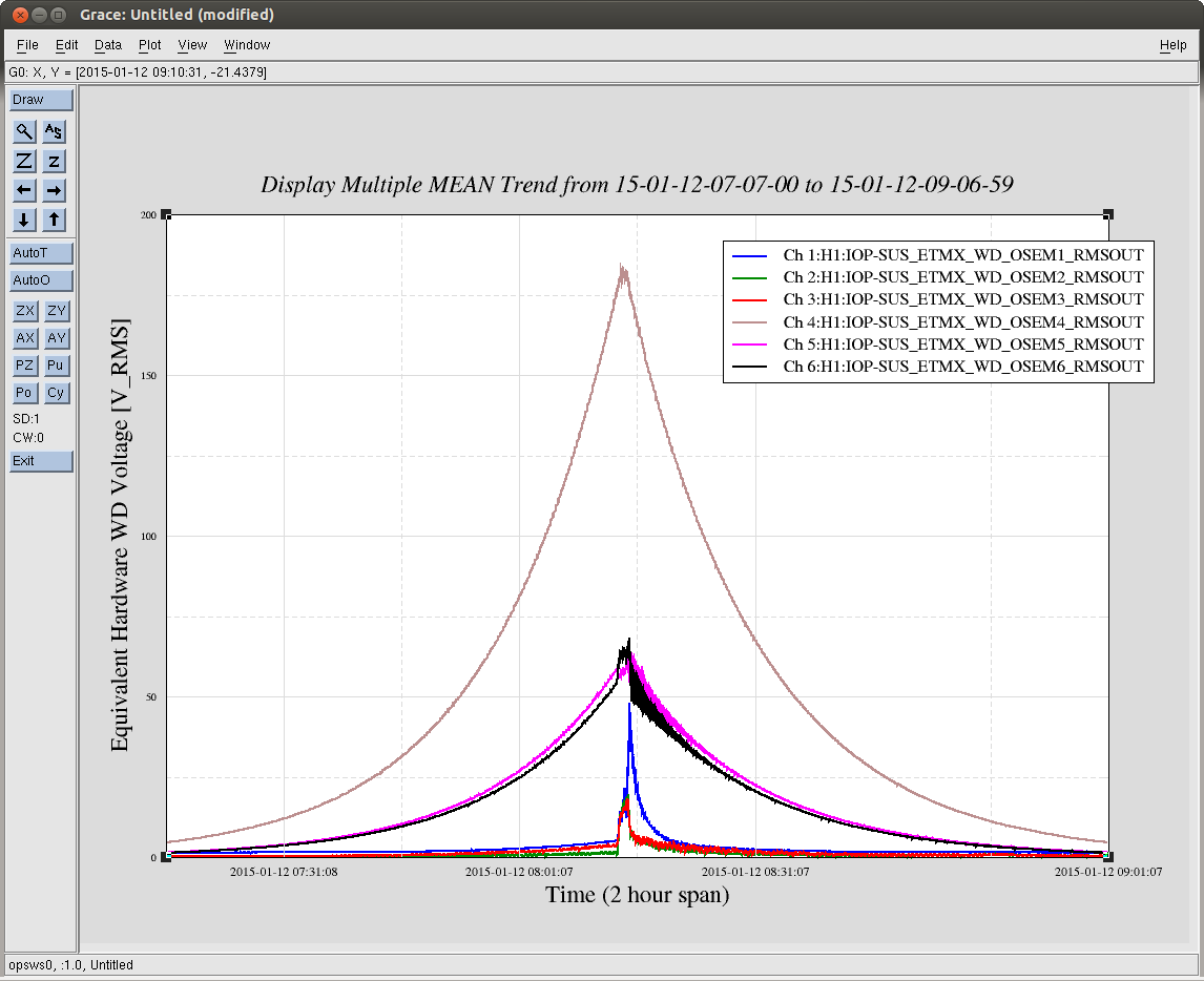
07:49 UTC - The ETMX SWWD begins to register that the QUAD's "OSEM4," i.s. Main Chain LF, a Vertical Sensor, is surpassing the 110 [mV] RMS threshold, originally defined by Jeff during the Hardware Watchdog testing (see LHO aLOG 12496. As stated there, this is roughly 10 +/- 5 [um] or [urad] peak-to-peak thoughout the ISI/ QUAD system. Note that the LF sensor is seeing MUCH more RMS than any other sensor, but RT and SD are the next biggest contenders, implying some sort of Roll / Transverse / RX / Y - ey kind of motion.
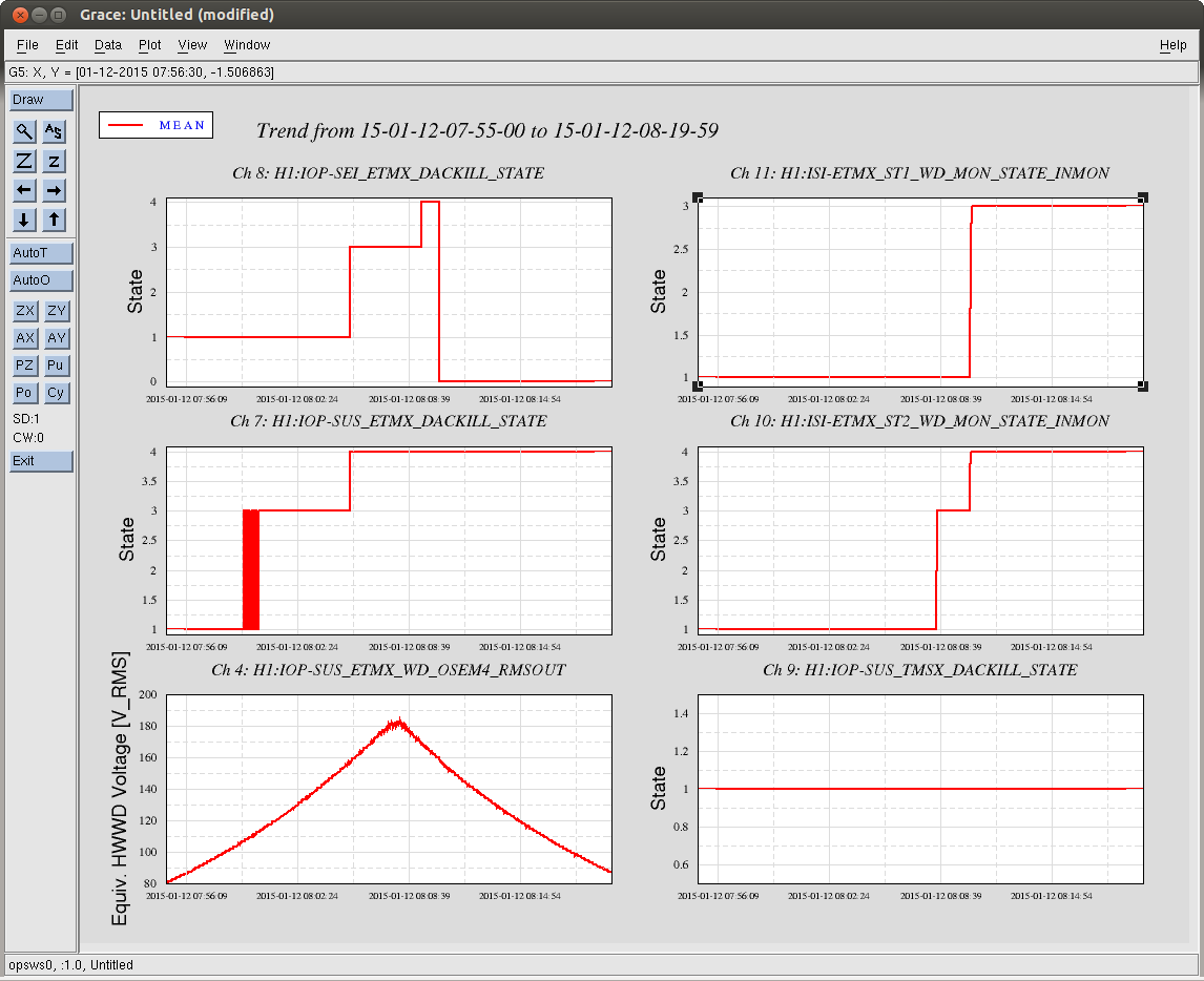
08:00 UTC - The SWWD's ETMX / QUAD watchdog is now constantly above threshold (State 3)
08:05 UTC - The SWWD ETMX / QUAD watchdog sends a warning to the SEI ETMX watchdog indicating things are getting serious (SUS WD goes to State 4, SEI WD goes to State 3), and shuts down the SUS DACs, tripping the all SUS IOP's DACKILL (for TMSX, ETMX M0, and ETMX R0).
08:08 UTC - The ISI's ST2 USER watchdog trips on the Actuators, but going only to State 3. This turns off ST2 X&Y, and the SWWD OSEM RMS begins to decline. << -- This points the finger at an ST2 X & Y instability (but ONLY when M0 is free).
08:09 UTC - The SWWD's SEI watchdog get the final 1 minute warning that the SEI DACs are about to be shut down (SEI WD goes to State 4)
08:10 UTC - The SWWD shuts down the SEI DACs, tripping the SEI IOP DACKILL (State 0). This sends both stages of the ISI to their USER WD State 4: full isolation shutdown.
I attach a whole bunch of plots I needed to back up this story.
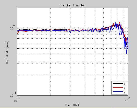
However, in addition to data mining, I *did* re-create the chamber configuration and take a standard SUS transverse transfer function, but gathered all of the ST1 T240s and ST2 GS13s as response channels, and plotted the transfer functions and coherence between M0 T and ISI Y RX and RZ -- 2015-01-12_2355_H1ETMX_WhiteNoise_tf.pdf
There's a lot of interesting information in there, but most importantly, there's a very coherent, transfer function at 0.46 [Hz] for all stages and all DOFs, with a magnitude of
Y/T [m/m] RX / T RZ / T
ST1 2.3e-4 1.3e-4 0.014
ST2 0.16 0.018 0.033


Frame size reduction was bogus. I checked too soon after the reboots when systems were not fully engaged and the frame was compressing zeros. After a few hours of ifo operation the frame sizes came up to nominal. Attached plot show commissioning and science frame sizes for the past two days.