jeffrey.kissel@LIGO.ORG - posted 14:18, Friday 06 February 2015 - last comment - 10:15, Thursday 12 February 2015(16511)
H1 SUS ETMX UIM (L1) Driver Power Switch Trips -- Now Turned Back ON
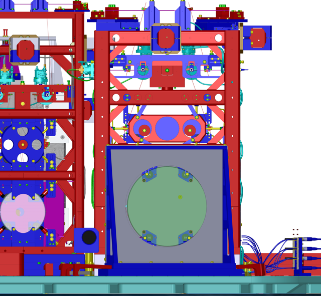
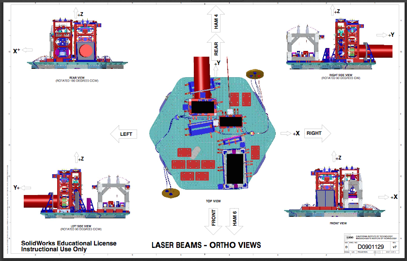
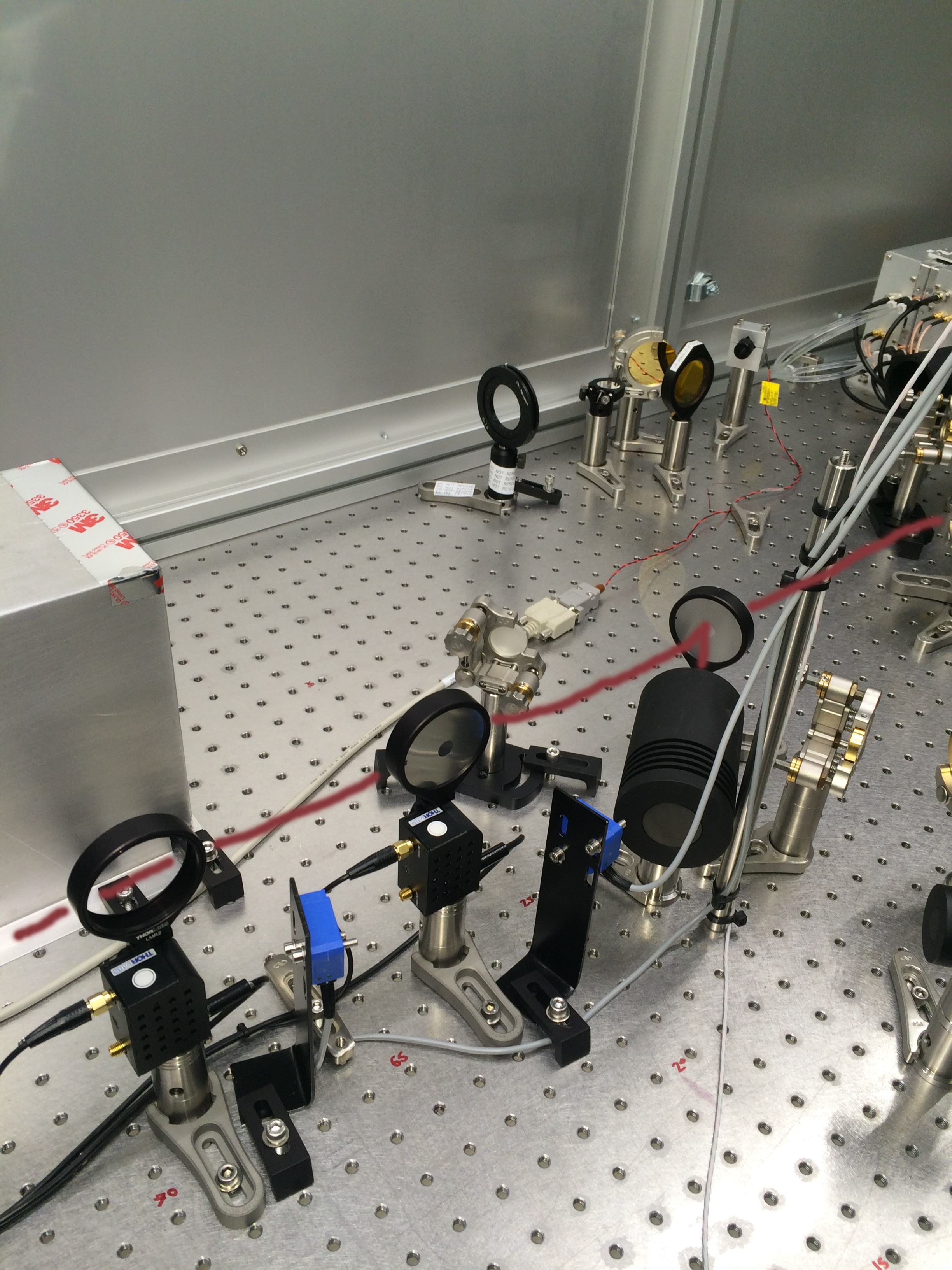
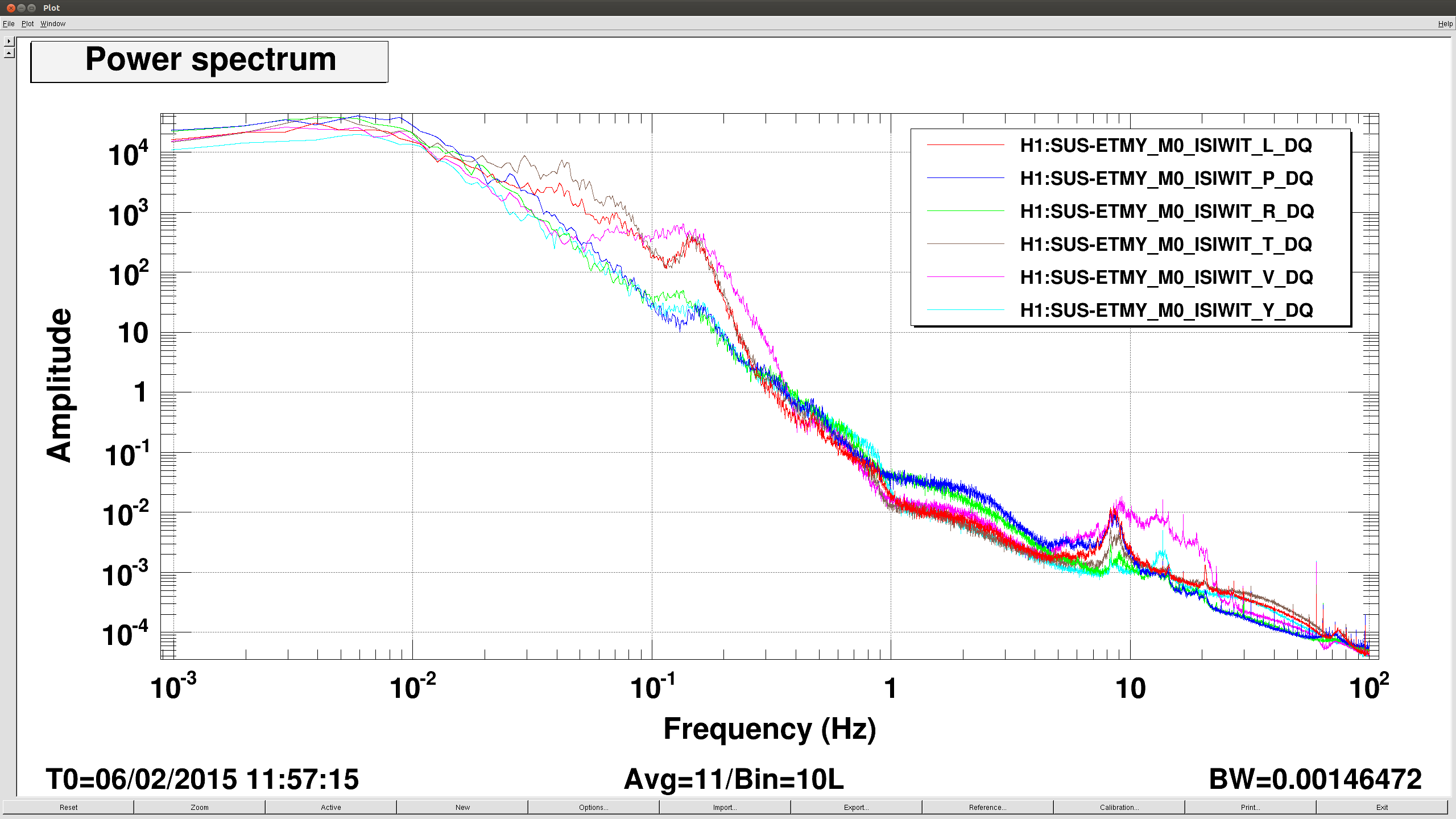
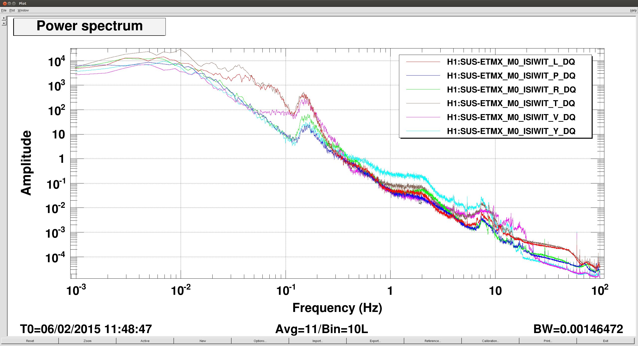
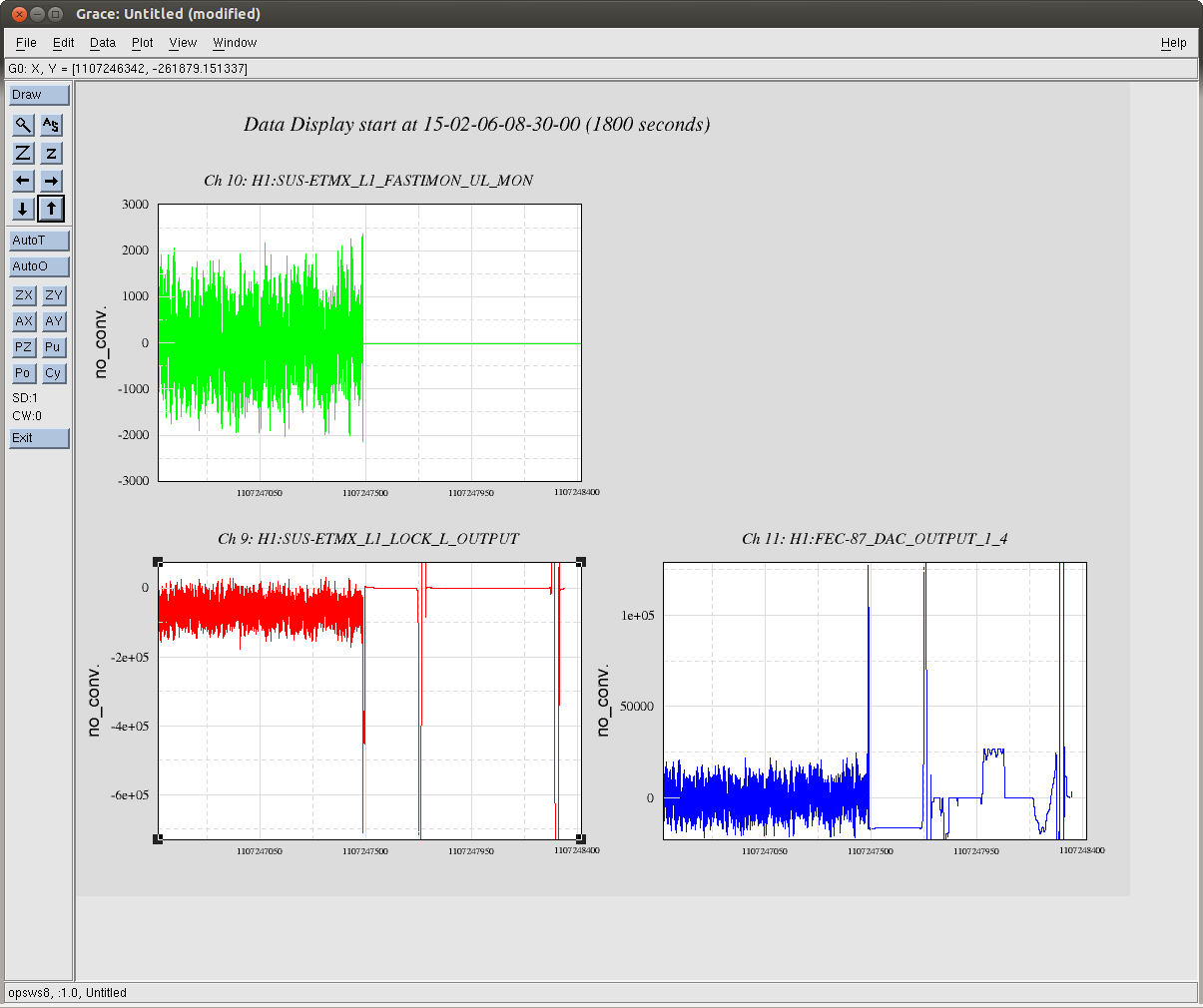
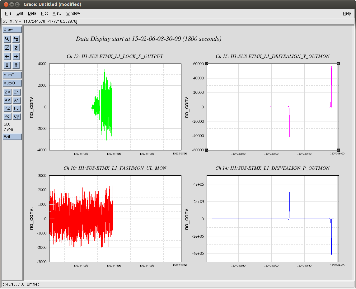
J. Kissel

ETMX UIM Driver's rocker switch tripped last night at 8:44:30 UTC (Feb 06 2015 00:44:30 PST), which cause all OSEM output on the L1 / UIM stage (and the sensor signals as well) to fail.

I've turned on the rocker switch, and the stage appears functional.

Other points:
-------------
There is no smoking gun for this chassis power outage. There are not enough diagnostic tools in the frames to look at all possible suspects (power surge to the chassis [no power monitors], chassis overheating [no temperature sensors], an inconsequential component on say -- a monitor board -- smoking [only one of the four monitor signals for each channel are stored], too large a current request [the NOISEMON is stored, not the FASTIMON]).

Output request of DAC (from any ISC) does not appear to coincide with trip, but difficult to tell with dataviewer. There is an Longitudinal request to drive really hard, but it's unclear whether it's a the cause of or a result of the driver's power being shut off.

Output request is roughly 42 [mA] (according to FAST_I_MON) on all four coils leading up to trip, switch trips on 3 [A]. Even the sudden, very large output request does not cause any current larger than the 42 [mA] -- as reported by dataviewer / EPICs. Reqrettably, only the severely-high-passed-at-5-[Hz] noise monitor signals are stored in the frames, but I attach the time series of one of the coils anyways to indicate the exact time. It shows a nice smooth ramp down at the time of the chassis power down.

Serial number of this box is S0900303. I attach pictures of the box after I'd turned it back on. When I first approached the box, the front "power" LED lights were OFF, and the rocker switch was in the opposite (powered off) position.

I'm not sure if there is good way to make this power shut-down control-room visible. I did notice that all the coil driver monitor signals were frozen at -16 [ct], and that the OSEM sensor speed dials were zero for this stage and this stage alone, which is what immediately clued me in that it was a flaw with the entire coil-driver chassis or satellite amplifier.

This last happened (according to collective analog CDS crew's memory) on H1 SUS ITMX UIM driver, some time ago, 19 November 2013. See LHO aLOG 8635.
Images attached to this report
Non-image files attached to this report

Comments related to this report
What's going on here?
Images attached to this comment
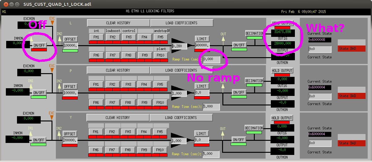
Adding more to Daniel's comment -- the problem in the screen shot he shows is ONLY a problem with the reported decimation filter output for the ETMX L1 LOCK L bank. He had repeated the same test on the ETMX L1 LOCK P bank, and saw no difference between the OUTPUT and OUT16. It's not an issue progressing forward because no one and nothing uses the decimation channel but for diagnostics, but it's this kinda of stuff that makes users immediately suspicious of the entire front end code as a whole (regardless of how serious the problem actually is) and demand "REBOOT! REBOOT!" without really identifying the specific problem.

Again, all signs point to that this is UNRELATED to the coil driver switching off from a current overload.

This being said -- I agree the decimation display problem with *this* filter bank *is* weird, and we'll try to debug further.
I have seen this too. Good to know its not just in my mind.
A couple more observations from bizarro land:
- The value actually flickers.
- The filter module below doesn't experience this.
- The same filter module in EY is also fine.
- Decreasing the offset by 10 and it is fine.
- Increasing the offset by 10 and still no good.
- Inverting the offset to negative and it is fine.
As indicated quickly by Daniel (LHO aLOG 16604), I restarted the front-end process for h1susetmy Tuesday morning, and saw no change in this behavior.

Since this bug seems to be extremely low impact, we should toss it into the CDS bugzilla for exploration of the flaw offline on a test stand to see if we can reproduce the error and hopefully debug. Also -- just because we like to blame everything new, it might be worth a check to see if this bug appeared after the RCG 2.9 upgrade, or after Daniel's Tidal Servo installation (see LHO aLOG 15601, or from his new Integrator filter module (LHO aLOG 15560), which is installed and feeding to/through the UIM L filter bank.