edmond.merilh@LIGO.ORG - posted 08:37, Thursday 05 February 2015 (16482)
PSL Weekly Reports
Images attached to this report
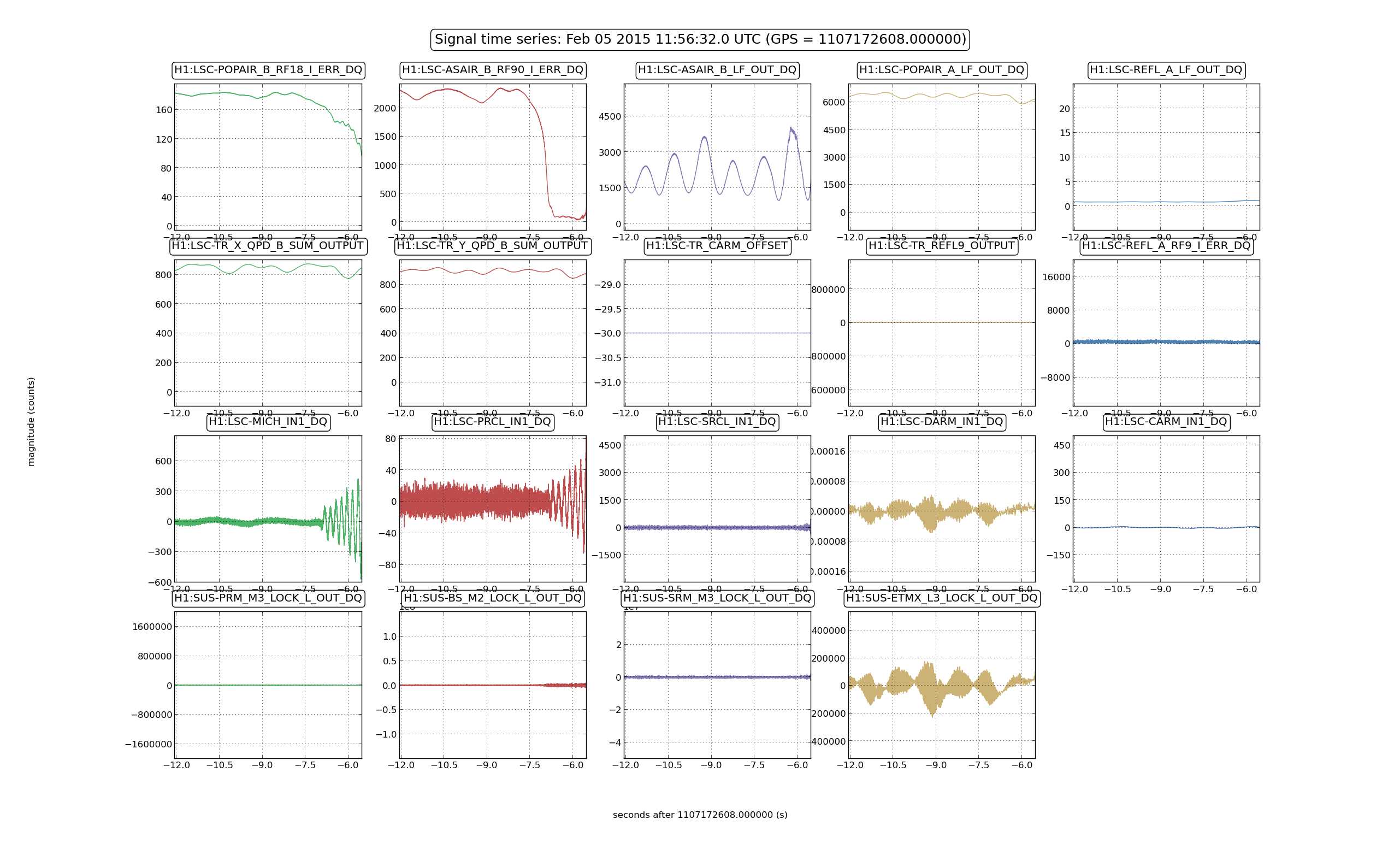
We had another lock of about 40 seconds, durring which all the signals seemed more stable than last night. It was knocked out by an oscillation that showed up in boh the MICH WFS and MICH length loops. We added an extra boost (2 poles at 0.1 and 2 zeros at 2Hz) to the CARM path, which seems to have made things more stable. The lockloss time was 11:56:32 UTC Feb 5th.
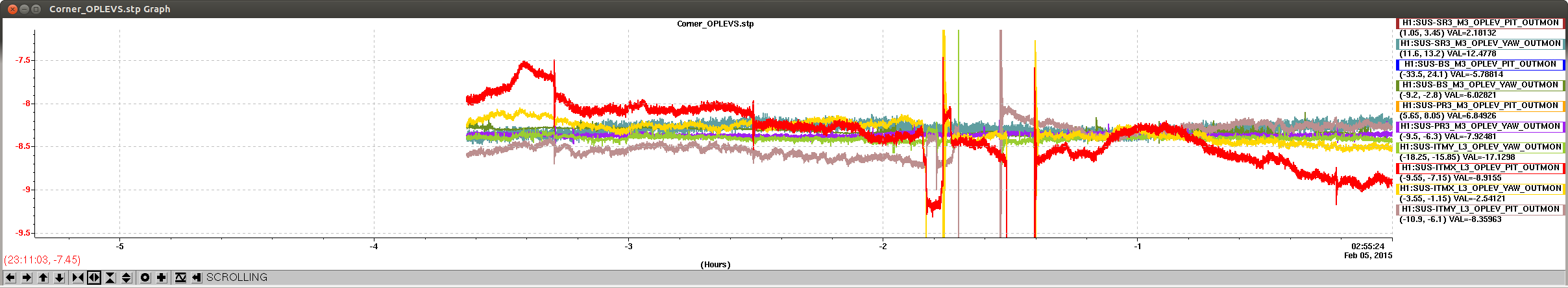
Today we saw that our alingment was drifting much more quickly than we had seen in the last few weeks. Without ASC we could only lock DRMI for a few minutes before MICH would get misaligned. The attached screenshot shows the slow drift of ITMX pitch, the red trace, which is about 1.5urad over the last 3 hours. We are not sure if this is real or just OpLev drift. Wspent some time on the MICH ASC loops. We phased ASB 36 so that the BS shows up in Q, and saw that this is a better signal for the WFS throughout the CARM offset reduction, which is what Ryan says they saw at LLO as well. They come on with a bandwidth of about 1 Hz, and hold the DRMI buildup is stable.
We also ran into difficulty tonight with the PSL rotation stage, it stopped responding to the command button for several hours. We need some code that checks if the input power is really the requested power, or we could try running through the whole sequence at the same power.
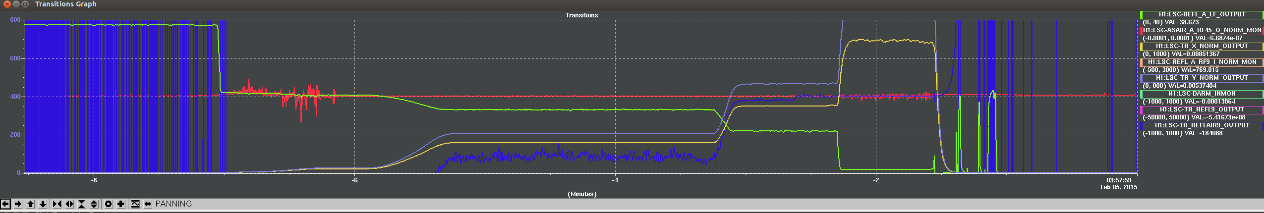
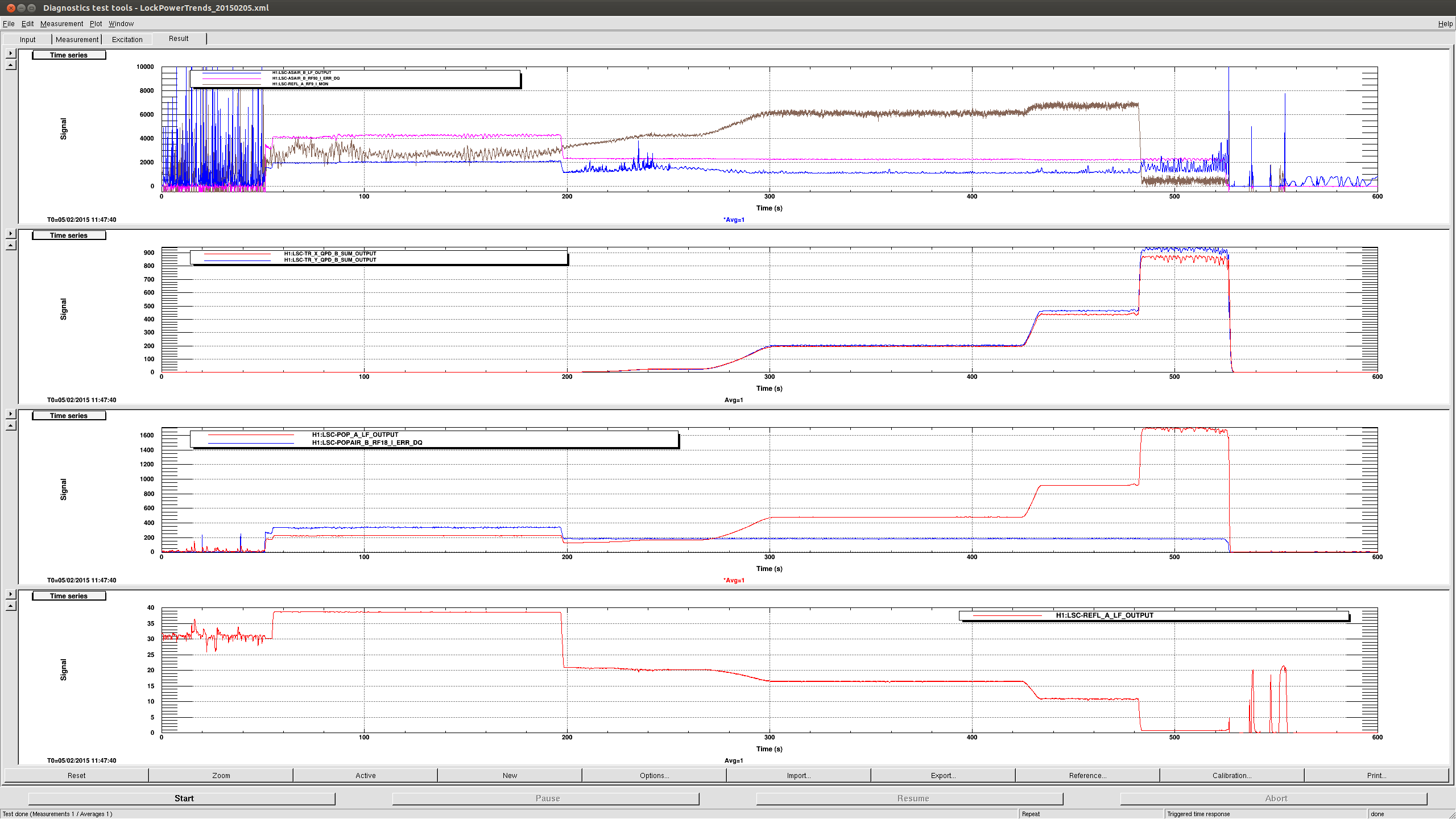
Here is a StripTool of the lock acquiistion. My DTT trend is taking too long to run, and I am tired...
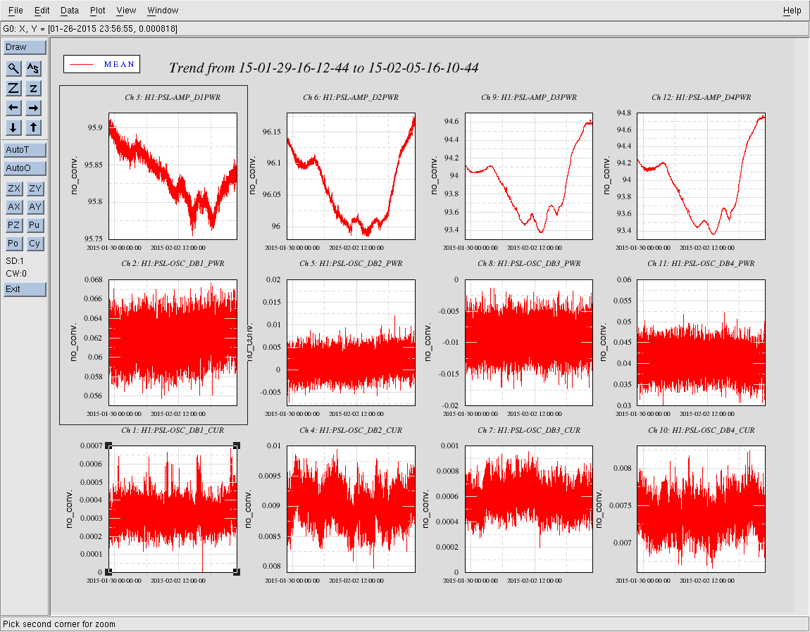
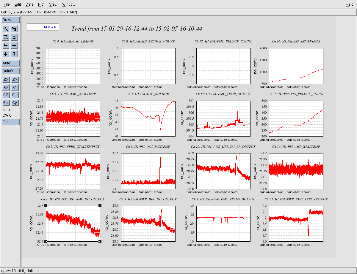
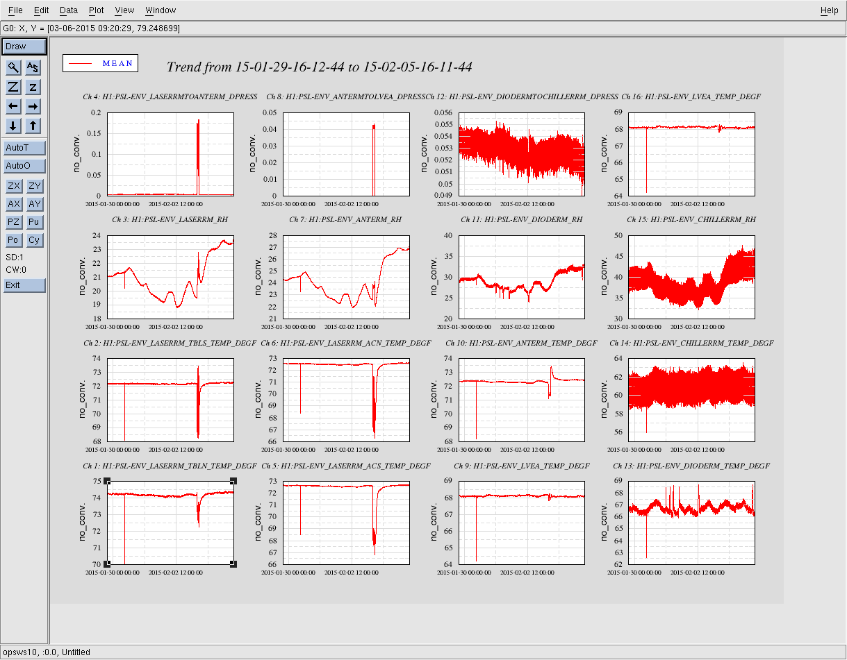
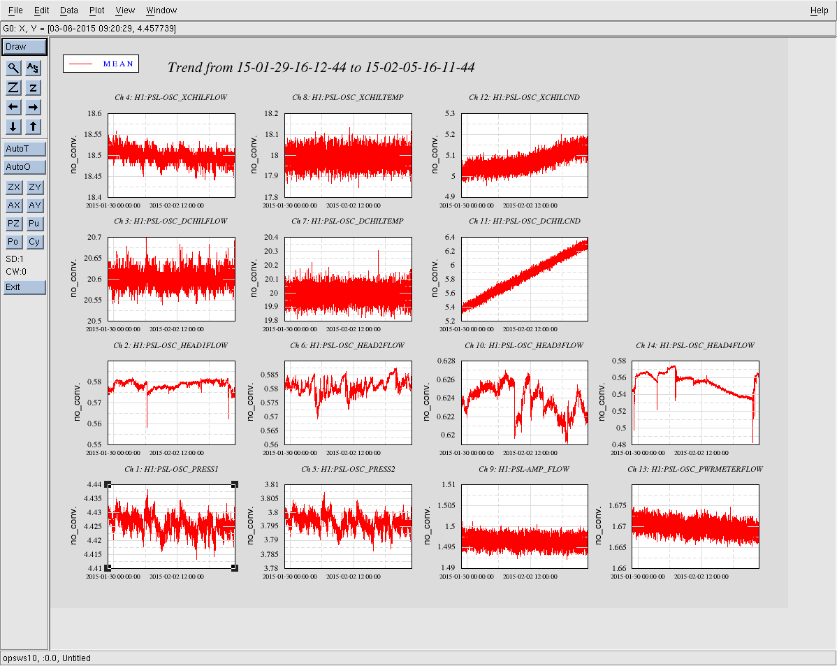
I have attached the temperature plot during the lock time (time at lock loss - 2 hrs). To see if the ITMX pitch drift was real I attached the vertical dof of the top stage as well...
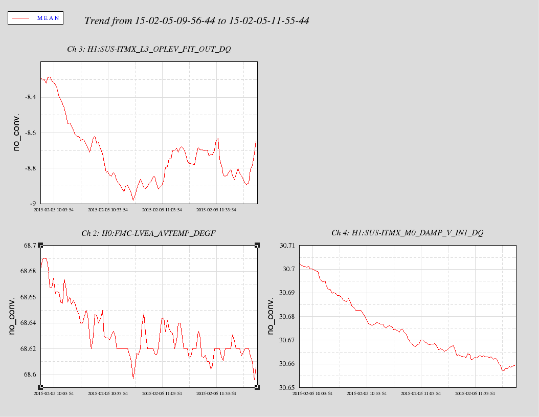
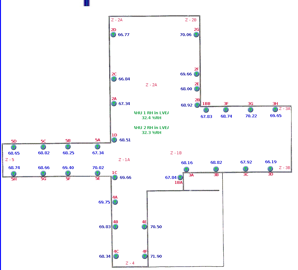
The LVEA average temperature is taken from many sensors. Here is a map of the individual temperature sensors - which are available in dataviewer, I believe.
For example the temperature sensor nearest ITM X might be Zone 3B sensor 3A.
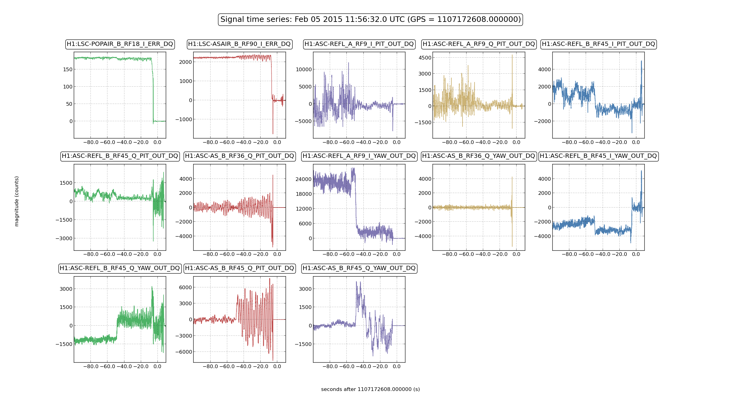
This lock event shows interesting things.

An oscillation in MICH is what eventually unlocks, but (I think) only because at that point the sideband power in the recycling cavity had significantly dropped.
As soon as REFL 9I is engaged,there is an oscillation ~ 0.45 Hz showing up in the AS RF45 and 36, and it is clearly visible in the ASAIR RF90 power.
The DARM length correction signal shows awful "bursts" at that point.
This is the lock trend I meant to post last night.
This is the conlog replica.

It appears to have started around 5:00 PM and repeated each hour after. I had to restart the database replication, it appears that the database has been crashing in response. It may not be a coincidence that the search for frequently changing channels also runs every hour, so I have disabled it.

cdsadmin@h1conlog3:/var/log$ grep error syslog
Feb  4 17:04:08 h1conlog3 kernel: [2335398.323116]          res 51/40:0a:16:e8:88/00:00:00:00:00/0b Emask 0x9 (media error)
Feb  4 17:04:08 h1conlog3 kernel: [2335398.323407] ata3.00: error: { UNC }
Feb  4 17:04:08 h1conlog3 kernel: [2335398.344358] Add. Sense: Unrecovered read error - auto reallocate failed
Feb  4 17:04:08 h1conlog3 kernel: [2335398.344367] end_request: I/O error, dev sda, sector 193521686
Feb  4 17:04:11 h1conlog3 kernel: [2335401.397976]          res 51/40:02:16:e8:88/00:00:00:00:00/0b Emask 0x9 (media error)
Feb  4 17:04:11 h1conlog3 kernel: [2335401.398264] ata3.00: error: { UNC }
Feb  4 17:04:11 h1conlog3 kernel: [2335401.420344] Add. Sense: Unrecovered read error - auto reallocate failed
Feb  4 17:04:11 h1conlog3 kernel: [2335401.420352] end_request: I/O error, dev sda, sector 193521686
...
I attempted a simple search and it crashed with the same syslog error. I am going to try to disable the webpage. Please do not try to use conlog until this is resolved.
To clarify, the acquisition of data appears to be ok, but the machine with the copy of the data that is used for user searches is not.
From the MySQL error log:

InnoDB: Error: tried to read 16384 bytes at offset 7 692060160.
InnoDB: Was only able to read 8192.
150204 17:04:11  InnoDB: Operating system error number 0 in a file operation.
InnoDB: Error number 0 means 'Success'.
InnoDB: Some operating system error numbers are described at
InnoDB: http://dev.mysql.com/doc/refman/5.5/en/operating-system-error-codes.html
InnoDB: File operation call: 'read'.
InnoDB: Cannot continue operation.
150204 17:04:13 [Warning] Using unique option prefix myisam-recover instead of myisam-recover-options is deprecated and will be removed in a future release. Please use the full name instead.
150204 17:04:13 [Note] Plugin 'FEDERATED' is disabled.
150204 17:04:13 InnoDB: The InnoDB memory heap is disabled
150204 17:04:13 InnoDB: Mutexes and rw_locks use GCC atomic builtins
150204 17:04:13 InnoDB: Compressed tables use zlib 1.2.8
150204 17:04:13 InnoDB: Using Linux native AIO
150204 17:04:13 InnoDB: Initializing buffer pool, size = 1.0G
150204 17:04:13 InnoDB: Completed initialization of buffer pool
150204 17:04:13 InnoDB: highest supported file format is Barracuda.
InnoDB: Log scan progressed past the checkpoint lsn 47921973351
150204 17:04:13  InnoDB: Database was not shut down normally!
InnoDB: Starting crash recovery.
InnoDB: Reading tablespace information from the .ibd files...
InnoDB: Restoring possible half-written data pages from the doublewrite
InnoDB: buffer...
InnoDB: Doing recovery: scanned up to log sequence number 47922305837
150204 17:04:13  InnoDB: Starting an apply batch of log records to the database...
InnoDB: Progress in percents: 0 1 2 3 4 5 6 7 8 9 10 11 12 13 14 15 16 17 18 19 20 21 22 23 24 25 26 27 28 29 30 31 32 33 34 35 36 37 38 39 40 41 42 43 44 45 46 47 48 49 50 51 52 53 54 55 56 57 58 59 60 61 62 63 64 65 66 67 68 69 70 71 72 73 74 75 76 77 78 79 80 81 82 83 84 85 86 87
88 89 90 91 92 93 94 95 96 97 98 99
InnoDB: Apply batch completed
InnoDB: Last MySQL binlog file position 0 4307, file name /var/log/mysql/mysql-bin.000221
150204 17:04:14  InnoDB: Waiting for the background threads to start
150204 17:04:15 InnoDB: 5.5.38 started; log sequence number 47922305837
150204 17:04:15 [Note] Recovering after a crash using /var/log/mysql/mysql-bin
150204 17:04:15 [Note] Starting crash recovery...
150204 17:04:15 [Note] Crash recovery finished.
150204 17:04:16 [Note] Server hostname (bind-address): '0.0.0.0'; port: 3306
150204 17:04:16 [Note]   - '0.0.0.0' resolves to '0.0.0.0';
150204 17:04:16 [Note] Server socket created on IP: '0.0.0.0'.
150204 17:04:17 [Note] Event Scheduler: Loaded 0 events
150204 17:04:17 [Note] /usr/sbin/mysqld: ready for connections.
Version: '5.5.38-0ubuntu0.14.04.1-log'  socket: '/var/run/mysqld/mysqld.sock'  port: 3306  (Ubuntu)
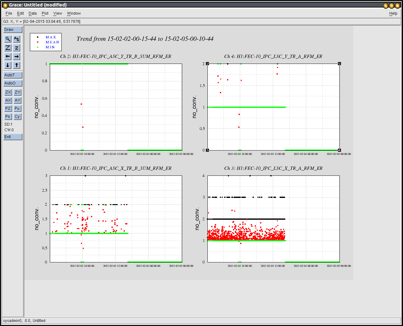
follow up on the ISC model split yesterday. Attached is a 3 day trend of IPC errors from end stations to LSC showing zero errors over the past 24 hours.
7:20 Karen - To LVEA
7:45 Cris - To LVEA
8:34 Betsy - To LVEA
9:05 Corey - To Squeezer Bay and West Bay
9:12 Kiwamu - To IO Table
9:44 RIchard - To CER
9:53 Betsy - Back
10:01 Corey - Back
10:25 Travis - To MidY
10:30 P. King, M. Heintze - To H2 Enclosure
10:50 Gerardo - EndX to take pictures of supply racks
11:48 Gerardo - Back
14:18 P. King - To H2 Enclosure
14:57 P. King - Back
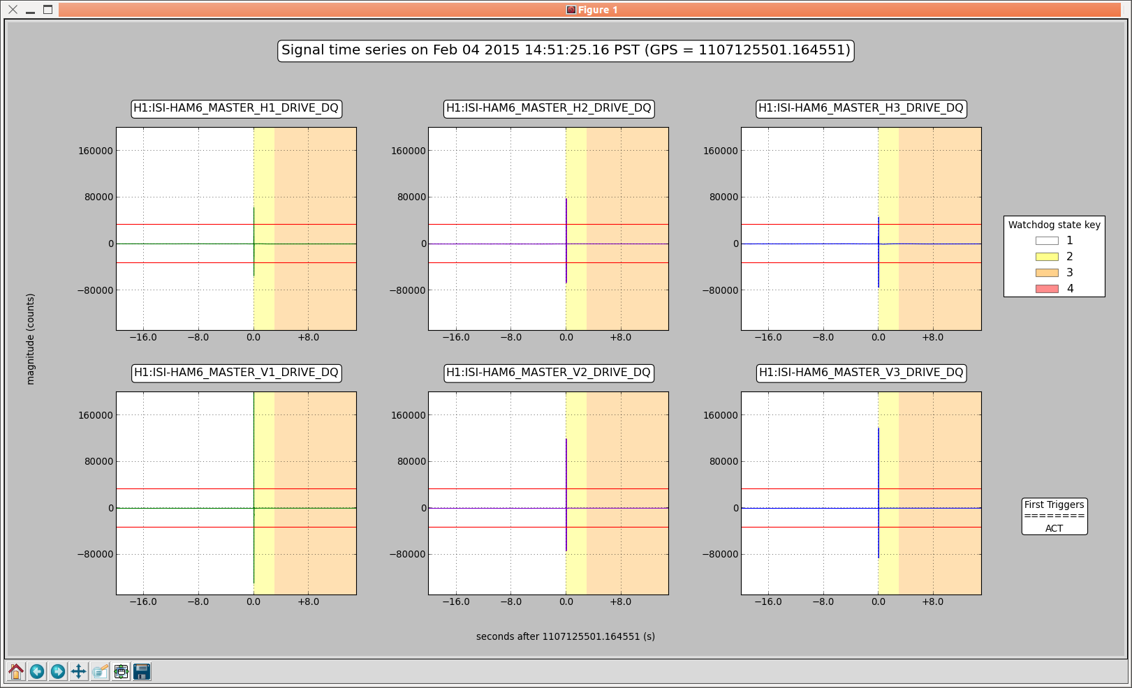
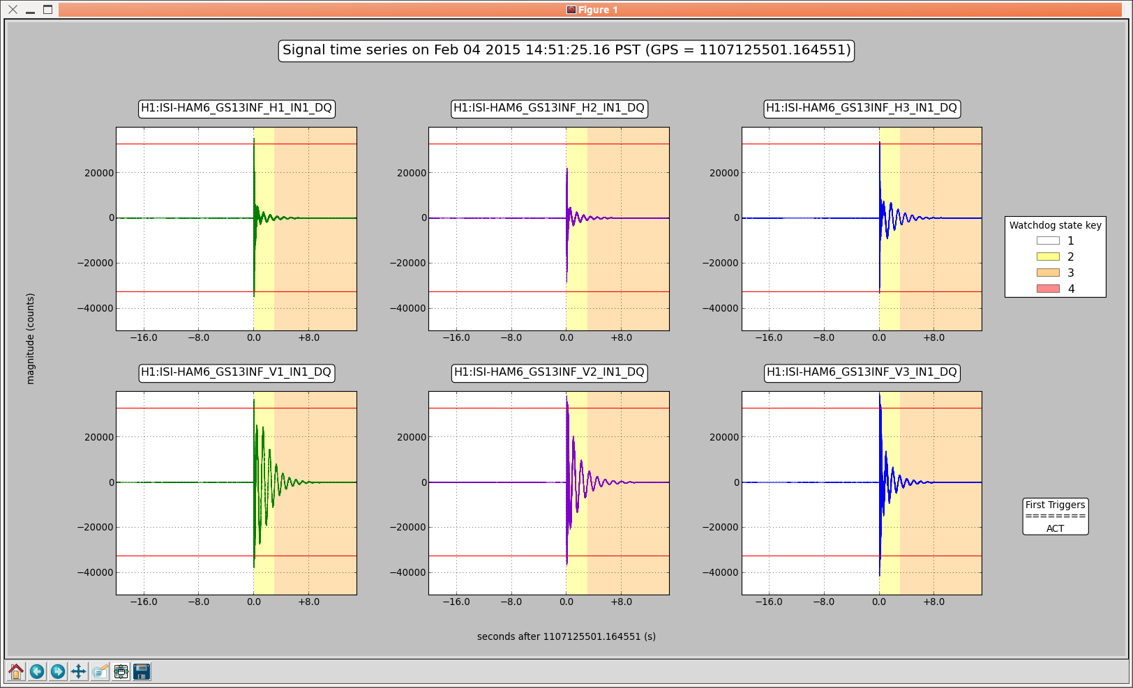
Tripped at 23:50 UTC. Plots of the trip attached below.
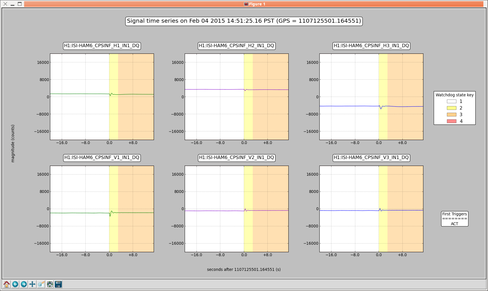
K. Venkateswara
I was looking at the BRS DriftMon signal to see how stable the BRS centering was, after being reset yesterday. I noticed very clear ~3.5 hour period oscillations. I know the beam-balance has a low resonance frequency but not that low! So I checked the temperature and sure enough it seems to be oscillating with 0.1 deg C amplitude. Note that it almost looks like the BRS is leading the oscillation, which is of course not possible. It turns out the temperature coupling has a negative sign ( as can be seen in 15174) and a lag of hours leading to a phase lag of ~160 deg, not a phase lead of ~20 degrees :)
This is probably not a big deal but I thought it looked cool.
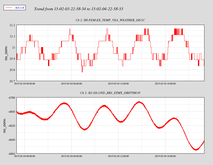
The temperature control is out of spec. It's too good!
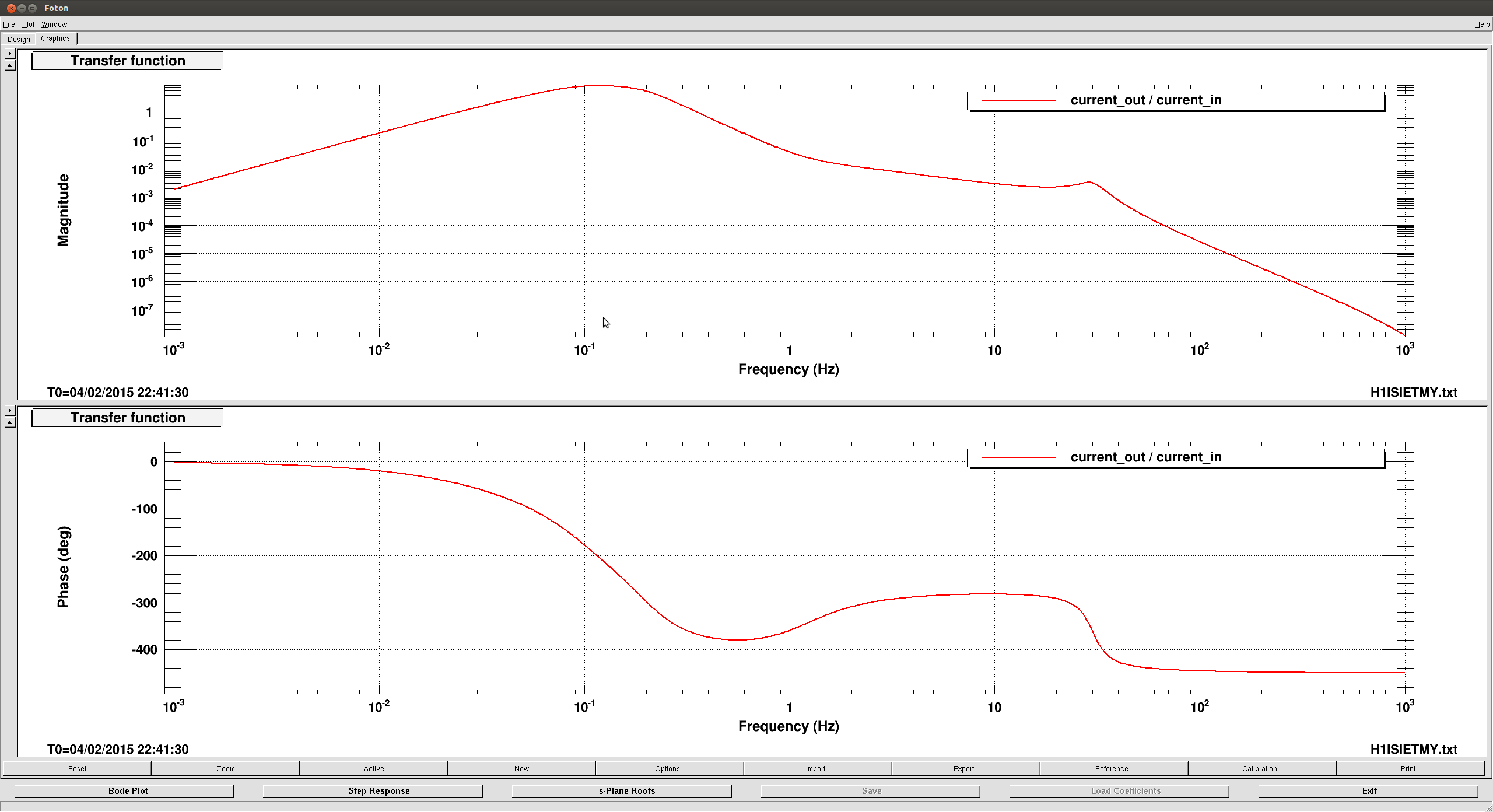
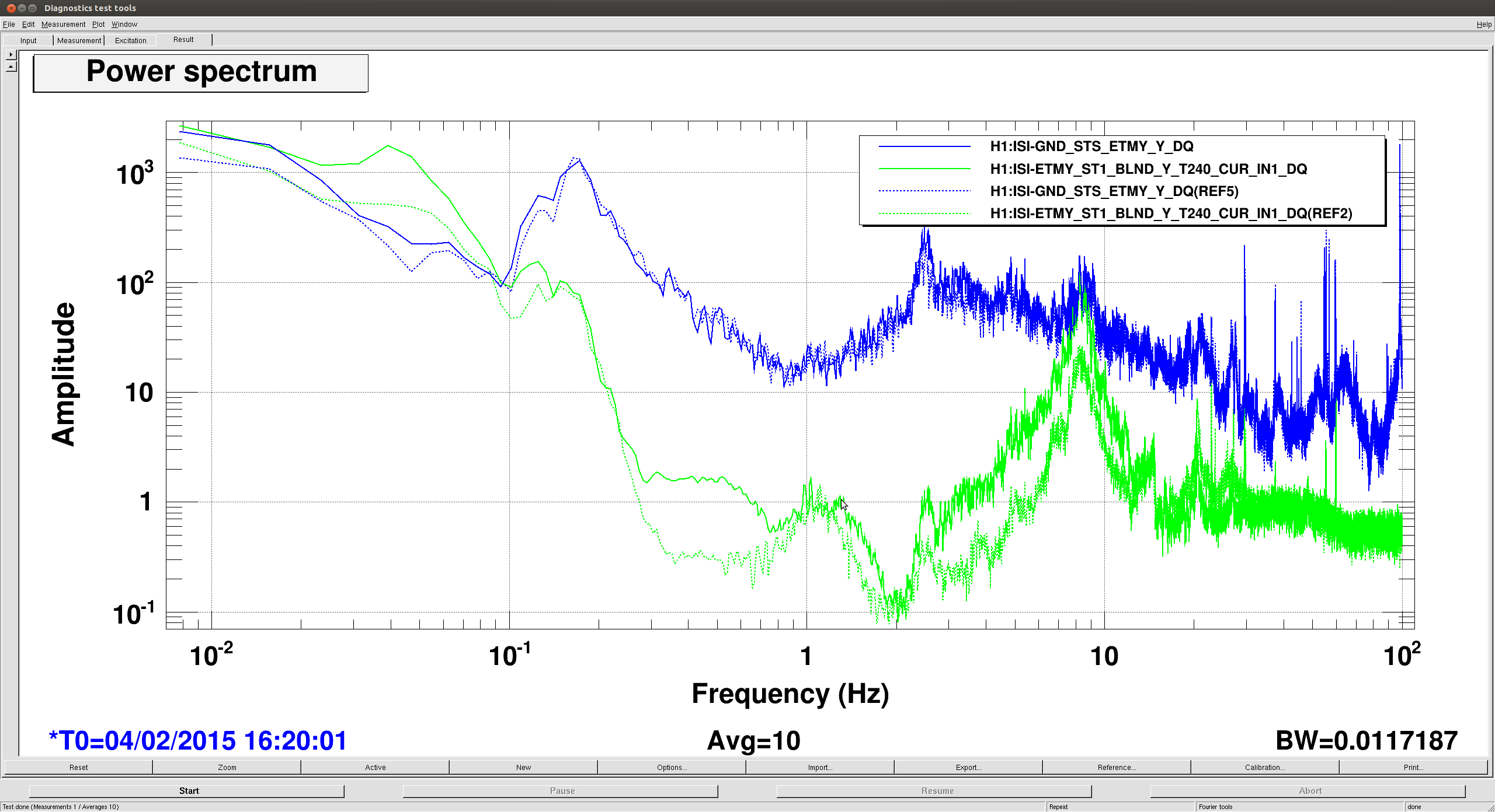
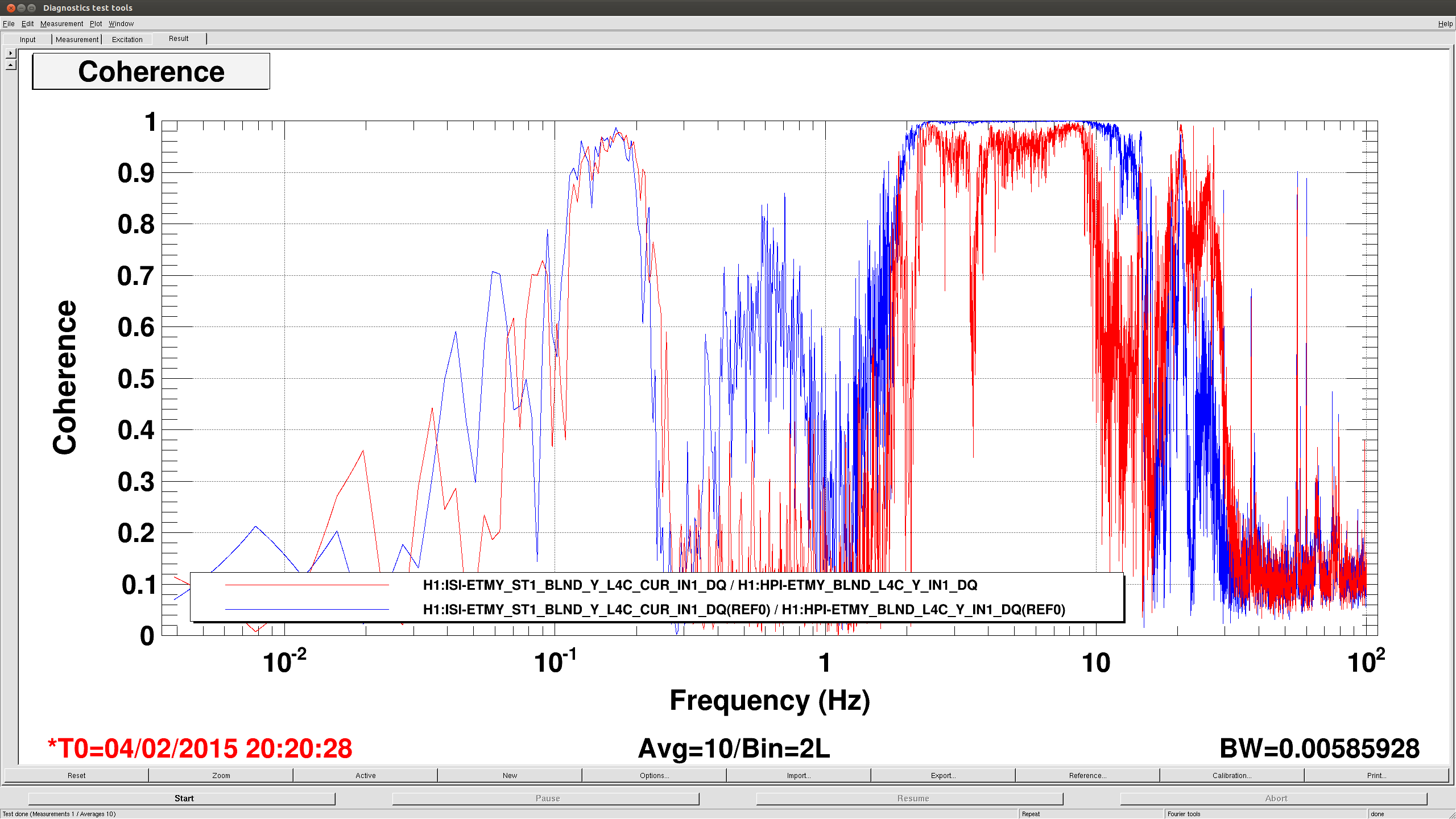
This morning, with prodding from Ryan, I tried turning on a feedforward filter left-over from Vincent's time on OAT. So far, I've only tried it on ETMY and it looks like it is doing good, and can maybe do better. The filter is Vincent's FF01-4 filter (first attached image). Looking at the ISI's T240's it looks like we are getting about a factor of 5 improvement at ~10hz (second image, solid lines are with FF off, dashed lines are with it on, blue is ground, green is the ISI). Finally, there is still coherence between the HEPI L4C's (the FF input) and the ISI's L4C's (last image, blue is off, red is FF on), meaning we can probably do a little better with some gain matching.
J. Kissel, for R. DeRosa

I asked Ryan -- "Why do we get performance improvement frm the ST0-1 feed-forward all the way down to the microseism and below?"
He replied -- "Not enough [feedback] loop gain!"
I paraphrase the rest of the conversation:
- Feed-forward adds extra control authority -- where ever it finds coherence -- without affecting the phase of the feedback loop. This is why we want to use it at ~10 [Hz], where there's plenty of coherence left with ST0, but it's tough to add more feedback loop gain while still maintaining good stability margins.
- Because the HEPI input / ST0 motion, as measured by the HEPI L4Cs, is still coherent down to the microseism (because there's not enough feedback loop gain), you still get appreciable feed-forward subtraction.
- We want to move the gain authority to the feedback loops, because a feedback loop enforces its own accuracy. In otherwords, feed-forward depends on gain matching and an extremely stable plant. In theory, yes, it doesn't really matter how you allocate the gain, but in practice, we desire an extremely robust system and the plant and sensors are liable to change at the 1% level, which results in a decrease in subtraction and therefore performance. (Assuming perfect phase matching, a gain mismatch of 1%, means you cannot subtract better than a factor of 100, 10% mismatch; never better than a factor of 10. And in practice we don't have perfectly stable phase matching either.)

Ryan will work with Jim tomorrow on designing some feedback loops which drastically increase the gain at low-frequencies, so that we're already gain limited below ~5 [Hz], and we only get the improvement from feed-forward between 5-20 [Hz], as I had expected.
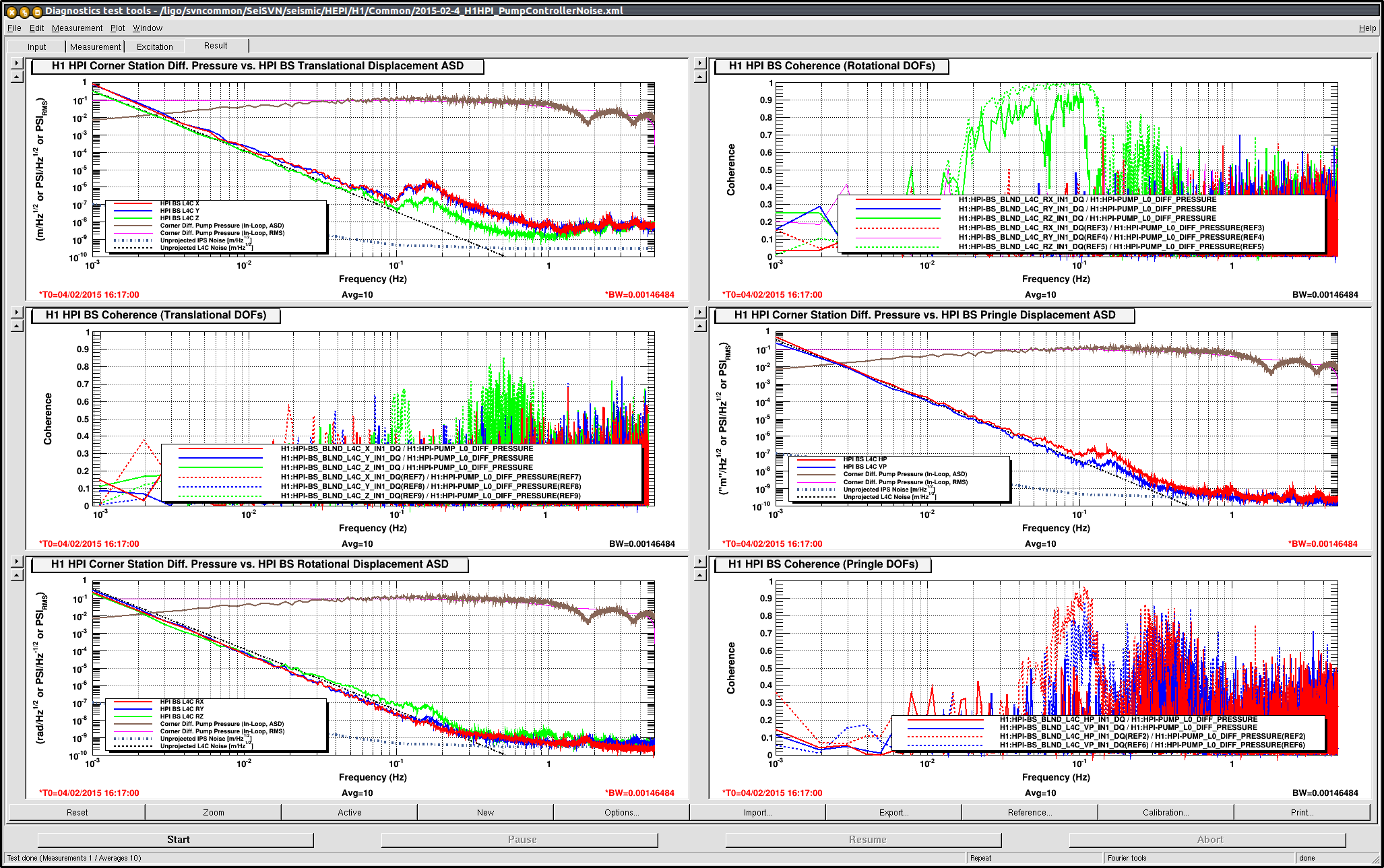
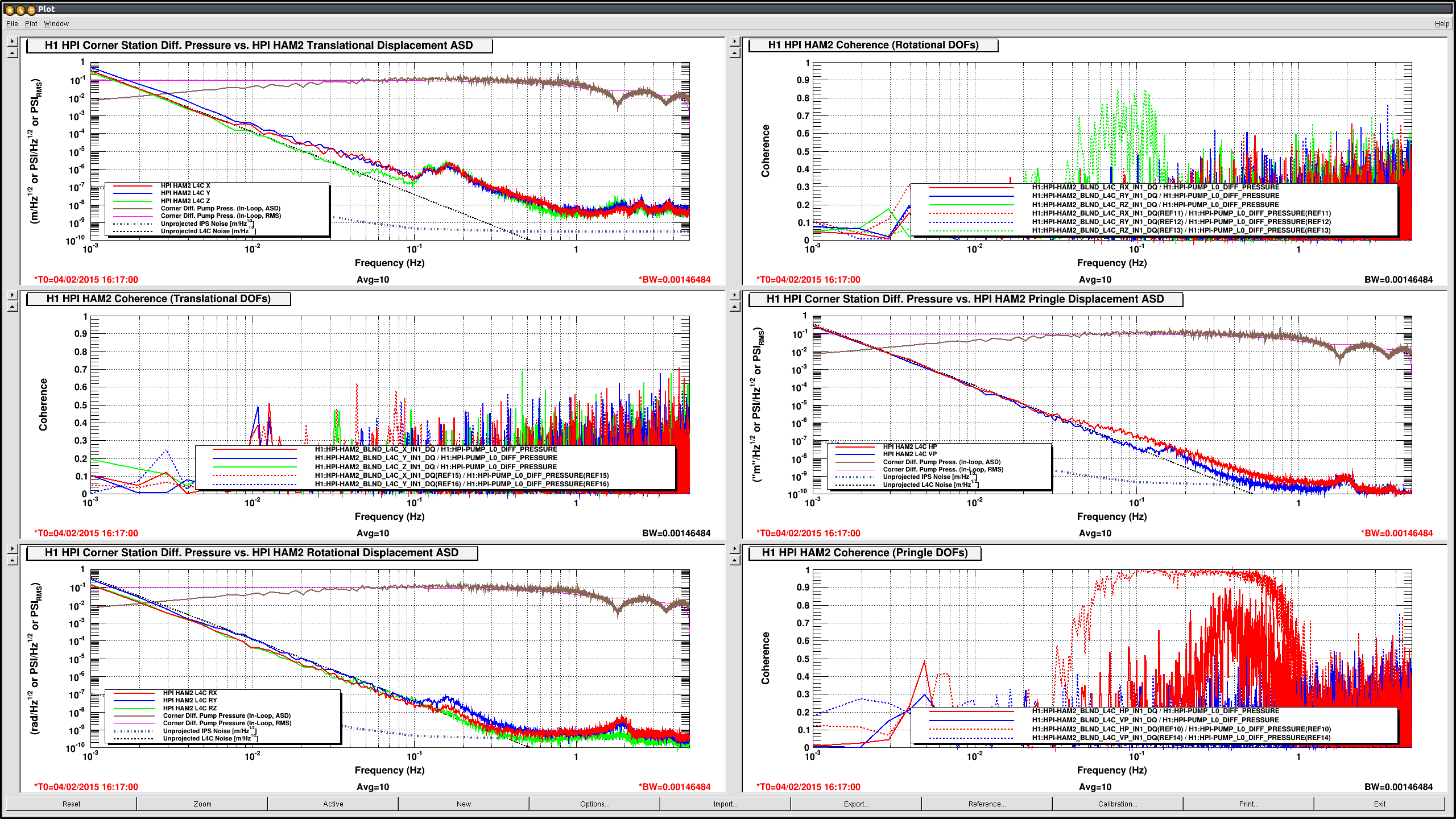
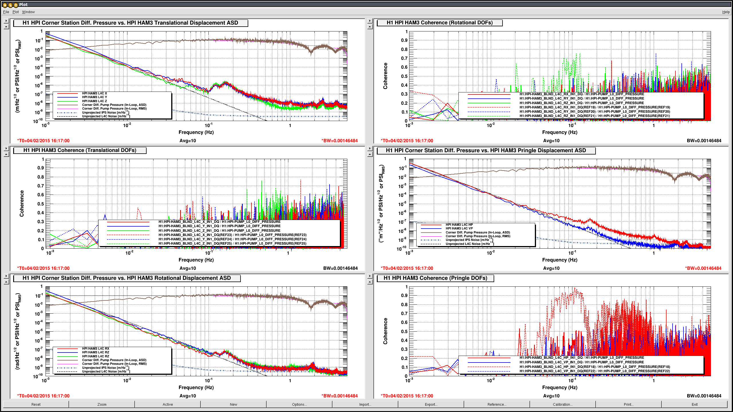
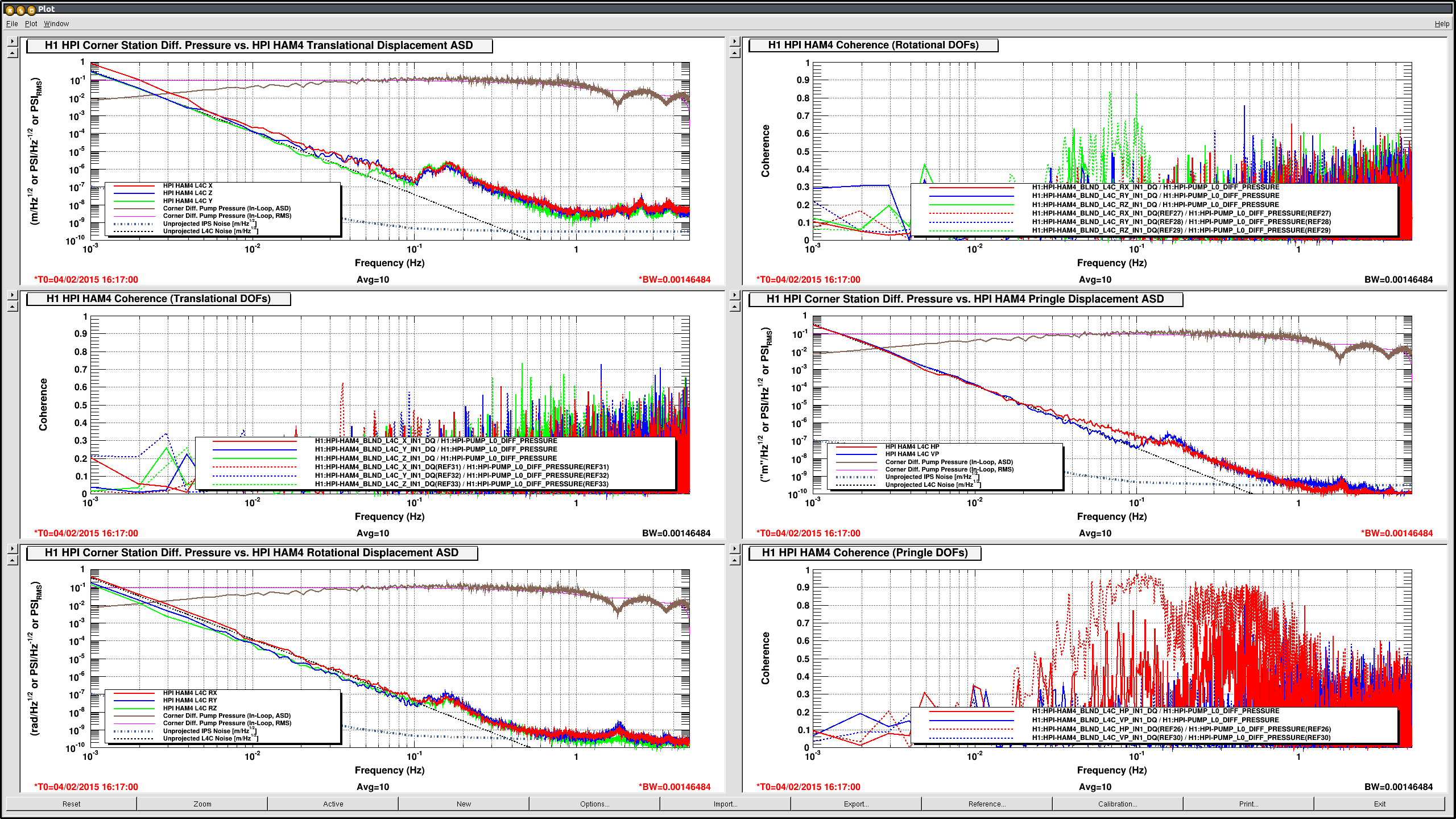
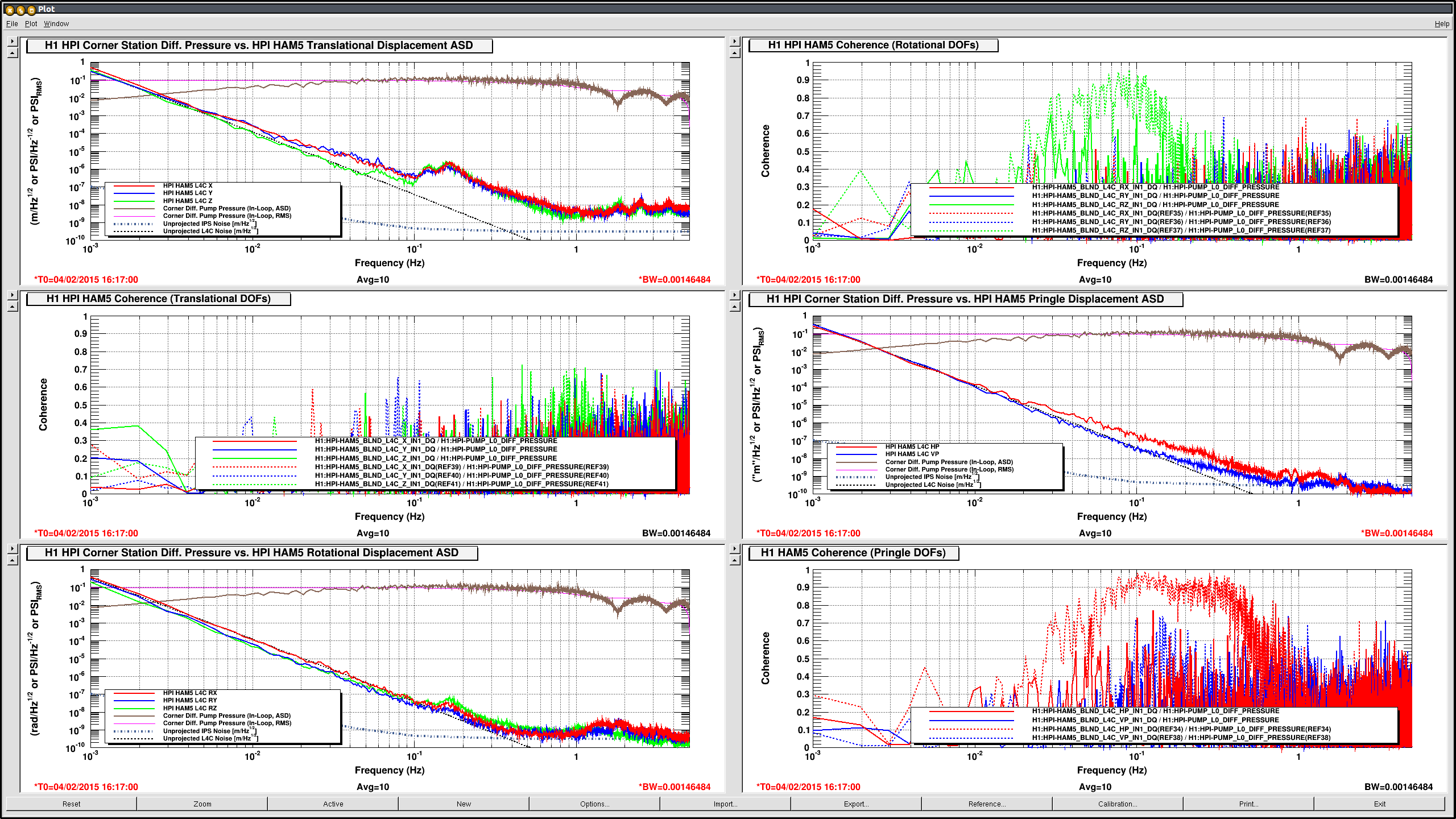
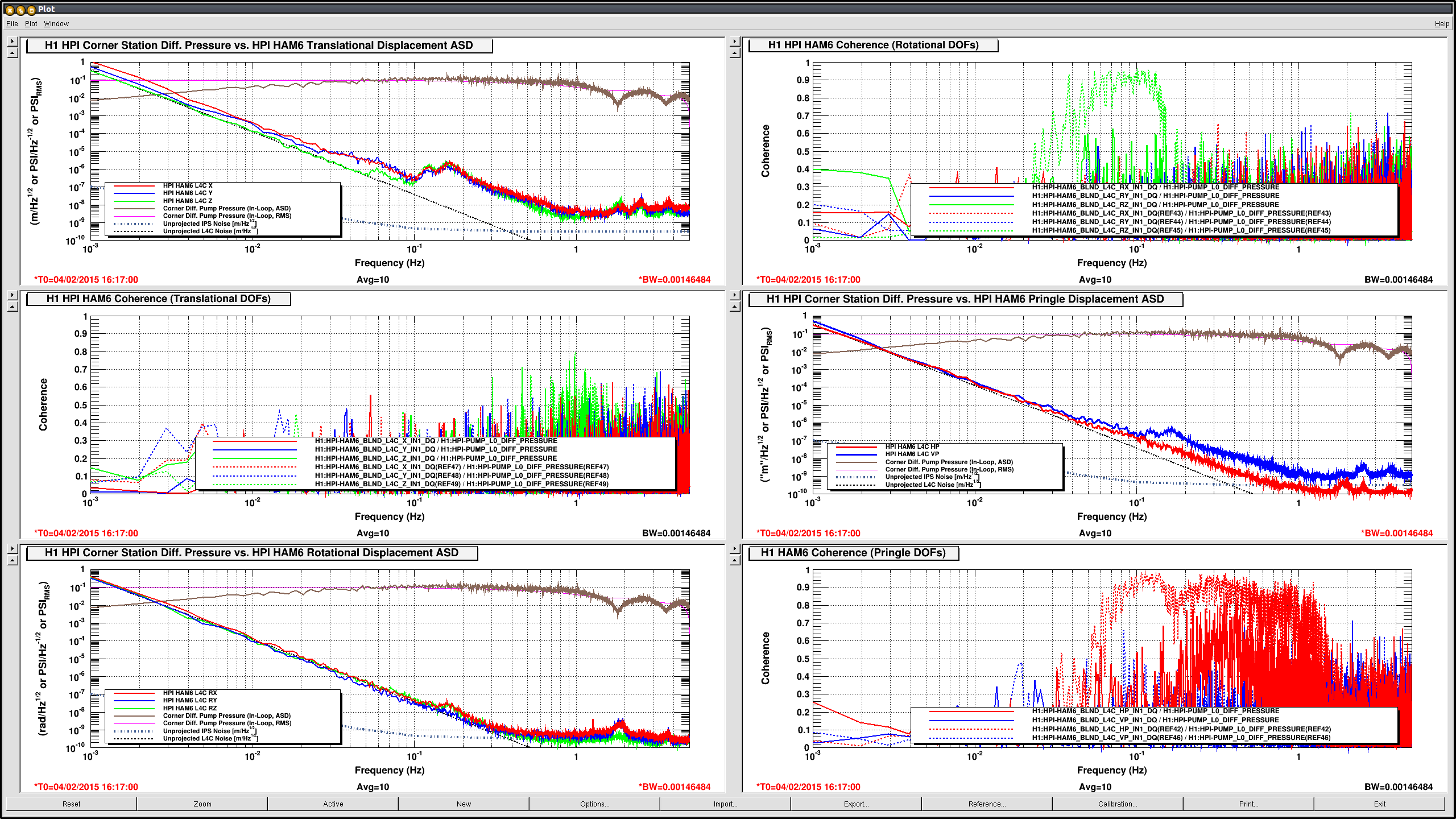
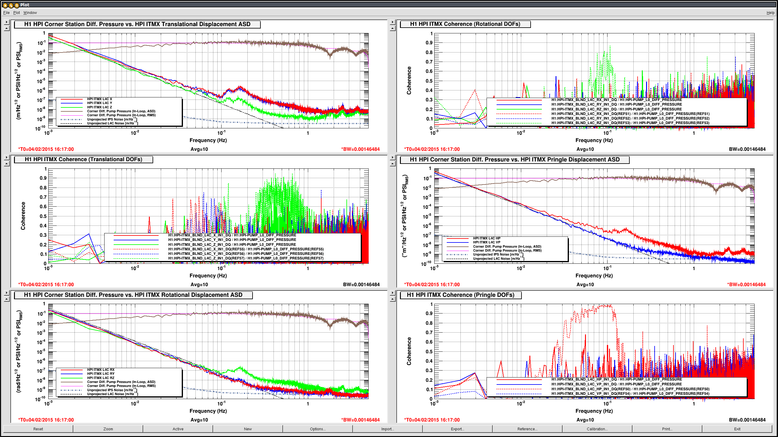
I lowered the PID parameters earlier. Here is the comparison: All coherences seen at 4am today (PID:35 & 0.45) are reduced a good amount (just a slight reduction on BS RZ) when the PID parameters are lowered to P=20, I = 0.07.
See the attached where the Dashed reference coherences are from 4am local today and the current Solid traces are at 8am with the lowered parameters.
Except for higher frequencies of the pringle coherences on most platforms, the Dashed coherences are much higher than the Solid traces. The BS RZ looks like an exception where the coherence only drops a bit.
xml 2015-02-4_H1HPI_PumpControllerNoise.xml is in /ligo/svncommon/SeiSVN/seismic/HEPI/H1/Common/
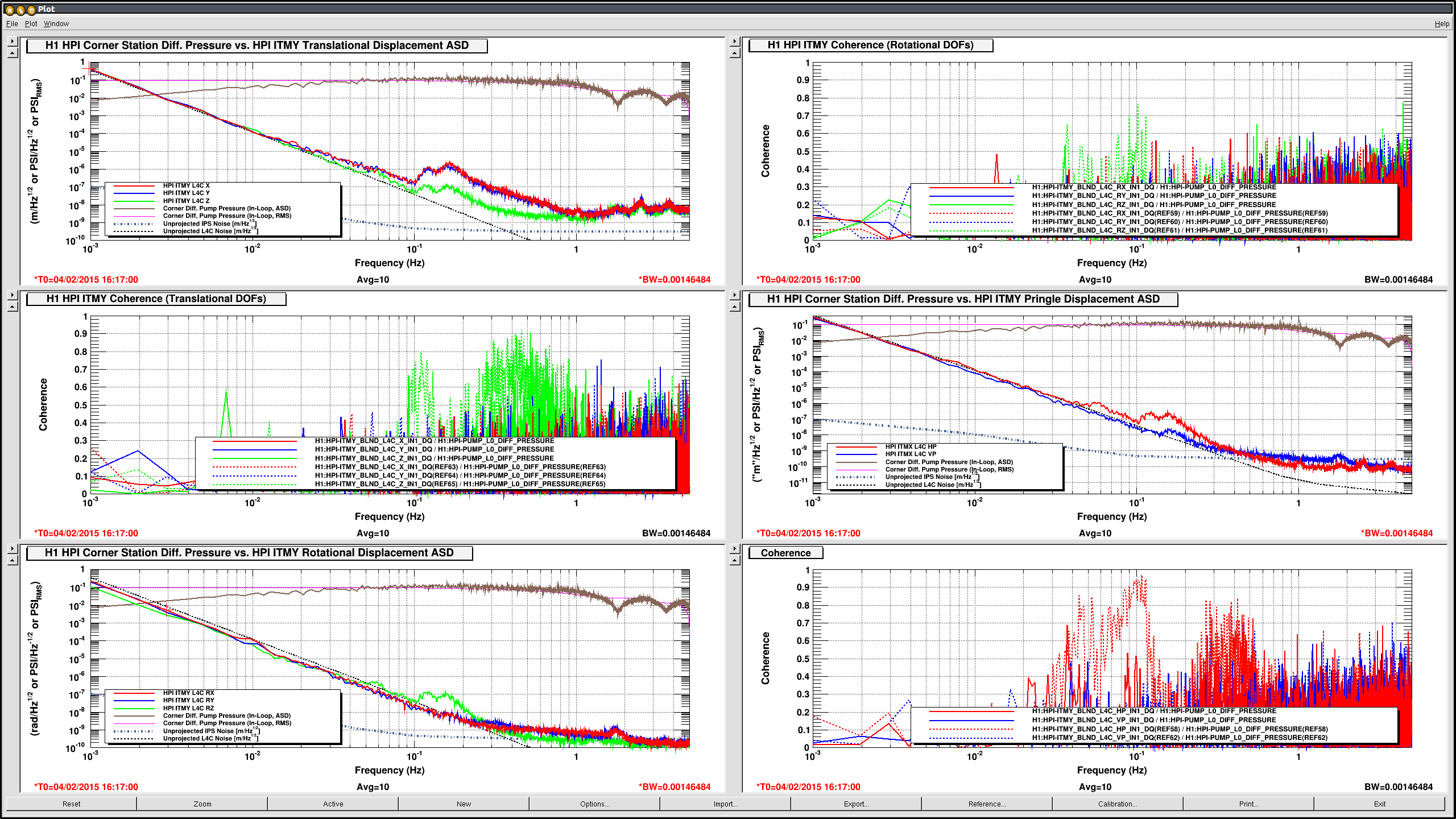
Even more confusing, I remeasure the ASD of the pressure sensor, and the loop suppression -- as shown by the ASD -- also gets modified (see first attachment), again differently than the model of the plant predicts (see 16447). This indicates that the HEPI Pump Servo box is doing *something* to it's error point, but that error point *is not* the correctly reported pressure noise because we've proven that the open loop noise looks identical to sensors disconnected noise (see LHO aLOG 16426).

Our next suspicion on the controller side of things is that the EPICs calc-record is not turning the EPICs requested P, I, and D into a control filter with the same units as reported on the screen. We'll

Suspecting DTT nonsense, I've also pulled 4000-second, time-series data from the frames directly into matlab using the nds2 client, using times reported in LHO aLOG 16426. I then calculated the ASD "offline" using asd2.m, to confirm that DTT doesn't screw up the FFT of an EPICs channel. The results are identical to DTT's results.

Next up:
- dive into the EPICs calc record to be sure that P I D parameters are getting turned into the controller we expect.
- measure the ASD of pressure sensor signals in analog, before they go into the HEPI Pump Servo, using an SR785.

They say the only we to really get to know a system is to fix it when it's broken. Welp, I'm certainly getting to know this system...
Added 1014 channels. Removed 26 channels.
Krishna, Jim, Ryan,
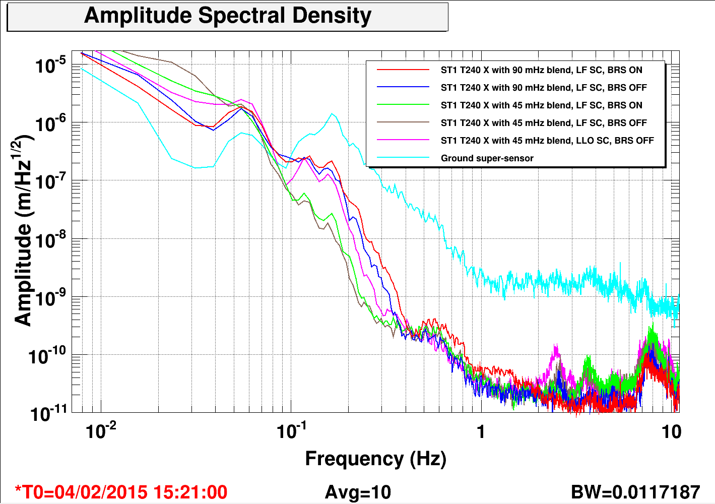
This morning, we tried some different blend filter and sensor correction configurations on the ISI at ETMX to see if we could improve the low-frequency performance of the platform.
To give some background, the nominal configuration along X axis, at present, is the 45 mHz blends and the LLO ("0.43 Hz only") sensor correction. The very low blend frequency amplifies the motion of Stage 1, likely through tilt reinjection. We wondered if we could do better by going to a higher blend and relying on a broadband low-frequency sensor correction, which uses the tilt-free super-sensor. We used the CPS sensors as the witness sensors, which should be reliable below 0.1 Hz and ST1 T240 as at higher frequencies.
The first attached plot shows the Stage 1 T240 X sensor ASD for the following configurations:
1. Red - 90 mHz blend and Low-Frequency Sensor Correction (LF SC, also known as Rich's filter or Z sensor correction filter).
2. Blue - 90 mHz blend, LF SC and BRS off (no tilt-subtraction).
3. Green - 45 mHz blend, LF SC with tilt-subtraction.
4. Brown - 45 mHz blend, LF SC with no tilt-subtraction.
5. Magenta - Nominal configuration - 45 mHz blend, LLO SC.
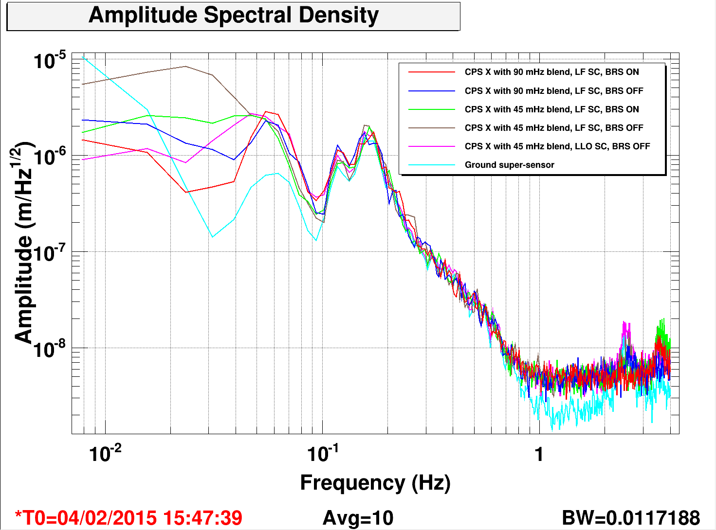
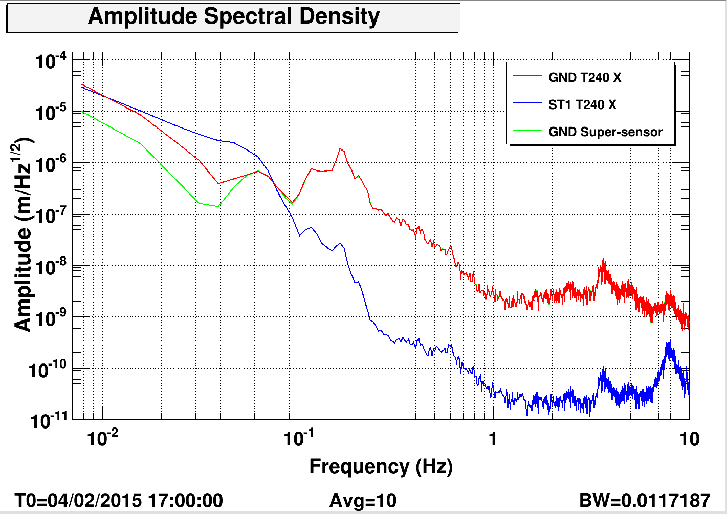
The CPS (before sensor correction) signals for the above configurations are shown on the second plot. These should be used as an estimate of the platform motion at low frequencies. The third plot shows an example of the tilt-subtraction. Wind speeds were between 5-10 mph at EX.
As expected (and seen before 15270), the Green/Brown configurations offer best isolation at the microseism. The rms CPS signal for Case 3 is about the same as Case 5. Turning BRS off shows the clear re-injection of tilt in Case 4.
In Case 1/2, there is still a factor of ~5-10 reduction at the microseism and the usual factor of ~200 at 0.43 Hz. The slight surprise was that in Case 1/2 there was a clear amplification of the primary microseism by factor of 4-5 which limits the rms motion of Stage 1. It is not clear why this is being amplified and is worth investigating further.
The tests were concluded by 9:30 AM and the ISI was returned to the nominal configuration.
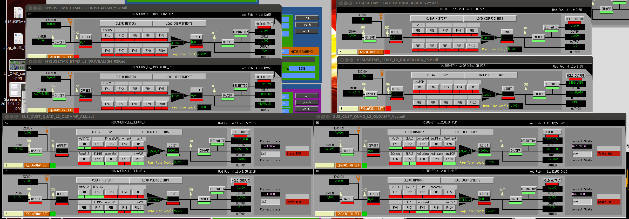
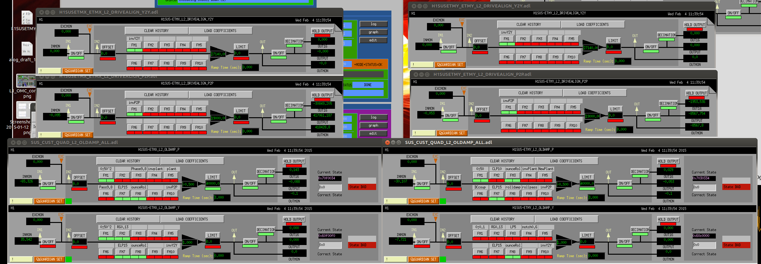
I've moved around filters (and gains) that are used in the OpLev damping, so that we can make try to increase the bandwidth of our DHARD WFS without driving through the high Q filters that have been used in P2P and Y2Y in the L2 drivealign matrix.
Even though we aren't currently using Yaw OpLev damping on either mass, I did the same for Yaw. Before and after screenshots attached.