Elli, Dan
On Saturday we made some changes to the DC centering loops in HAM6, for the AS WFS and the OMC.
==== AS WFS loops diagonalized ====
We started by measuring and inverting the sensing matrix for the AS WFS. The new control matrix has been loaded into the ASC output matrix. The old control scheme was AS-WFS-A --> DC3 --> OM2, AS-WFS-B --> DC4 --> OM1, all with matrix elements of unity. The new output matrix elements are:
|
DC3 |
DC4 |
Pitch |
|
-29 |
-419 |
OM1 |
|
410 |
109 |
OM2 |
|
|
|
|
|
|
|
Yaw |
|
-59 |
-423 |
OM1 |
|
-558 |
-111 |
OM2 |
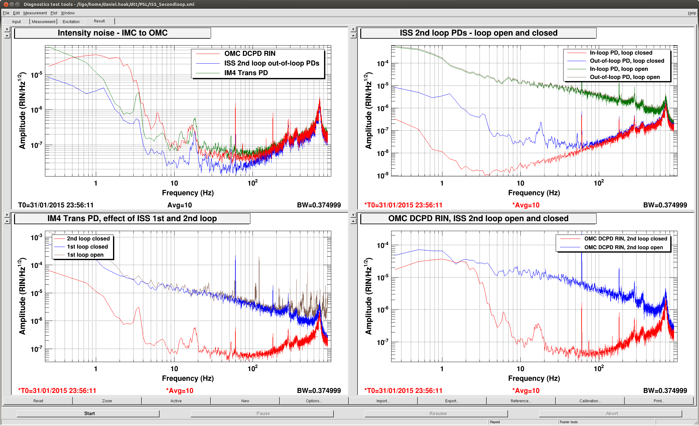
To compensate for the new matrix elements we changed the gains on the DC3 and DC4 loops to be 0.03. Based on the plot of the noise suppression it looks like this corresponds to a UGF of ~1-2Hz, but we need to measure the loop shapes during a break in the lock commissioning.
==== Alignment of OMC REFL path ====
With the fast shutter installed we felt confident to realign the beam going to the OMC REFL QPDs. Previously this path had been roughly aligned, but we hadn't worked out the assignment of the in-vac picomotors and centered the beam on both OMCR QPDs. The picomotors are on mirrors M9 and M10, see the diagram in D1000342-v14. Both picomotors are upstream of the OMCR QPD sled.
We centered the beam on OMCR_A and moved each picomotor until OMCR_A_SUM dropped to 50% of the peak value. Pico #6 moved half the distance of Pico #5, so we inferred that Pico #5 is driving M10 in the diagram, and Pico#6 is driving M9. So, the HAM6 picomotor assignment is:
|
HAM6 Pico driver box channel |
Mirror as labeled in D1000342-v14 |
|
1 |
M101 - AS WFS A |
|
2 |
M102 AS WFS B |
|
3 |
M7 - ASC-AS_C |
|
4 |
Not connected |
|
5 |
M10 - use to center OMCR B |
|
6 |
M9 - use to center OMCR A |
|
7 |
Not connected |
|
8 |
Not connected |
After centering the beam on the OMCR QPDs we checked ISCT6 to make sure the OMCR beam was still coming out. We found it was still well-aligned on the table (centered in periscope mirrors and lenses).
==== OMC SUS -> OMC {POS,ANG} transfer function and OMC alignment topology ====
To decouple the OMC alignment from the AS WFS centering, we wanted to use the OMC SUS as an actuator. (Following L1, we had added this functionality to the OMC and OMCS models in December.) The trick is to make the OMCS look like a simple pendulum so that the OMC ASC loops can drive OM3 (a tip-tilt) and the OMCS at the same time.
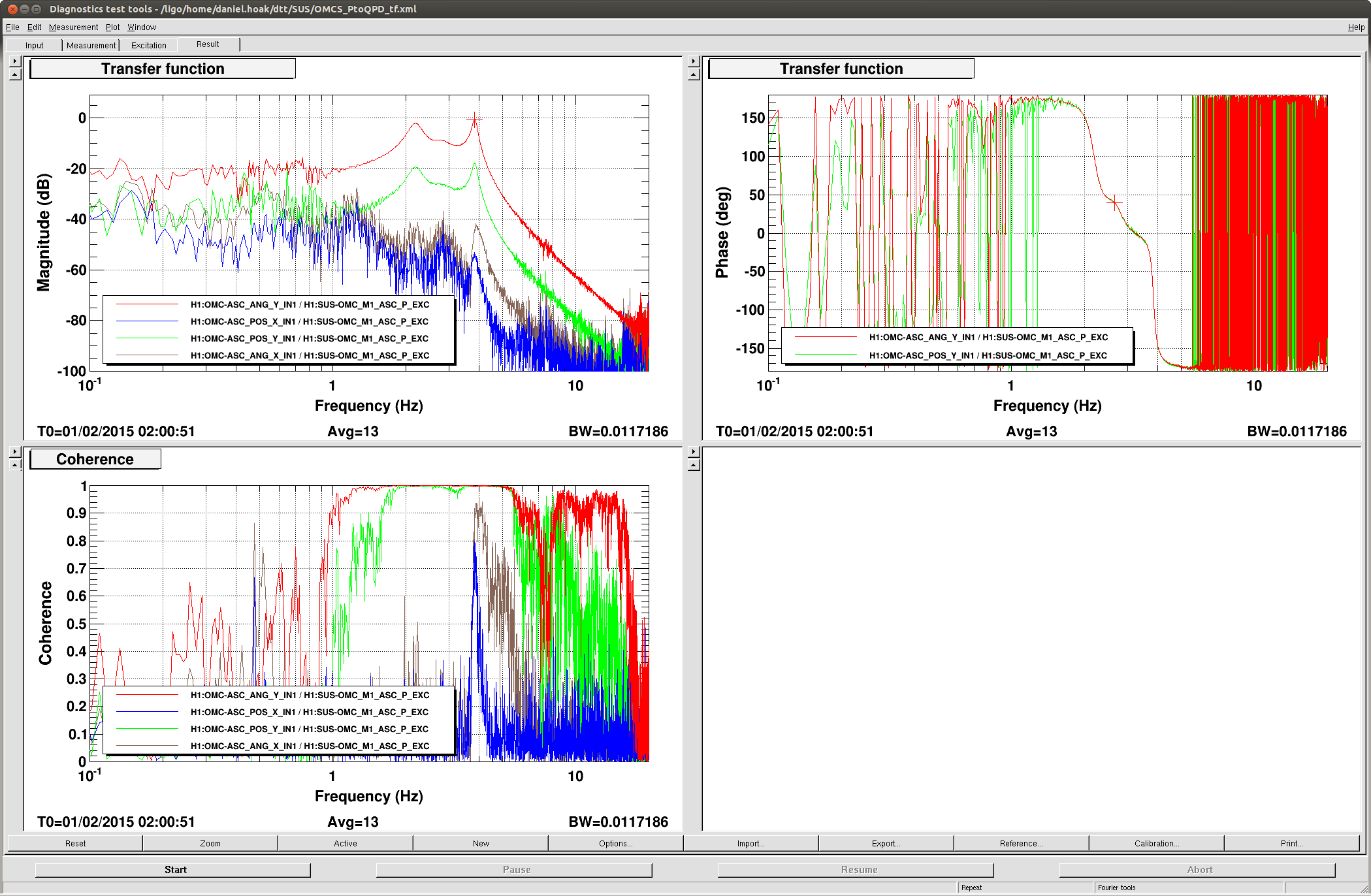
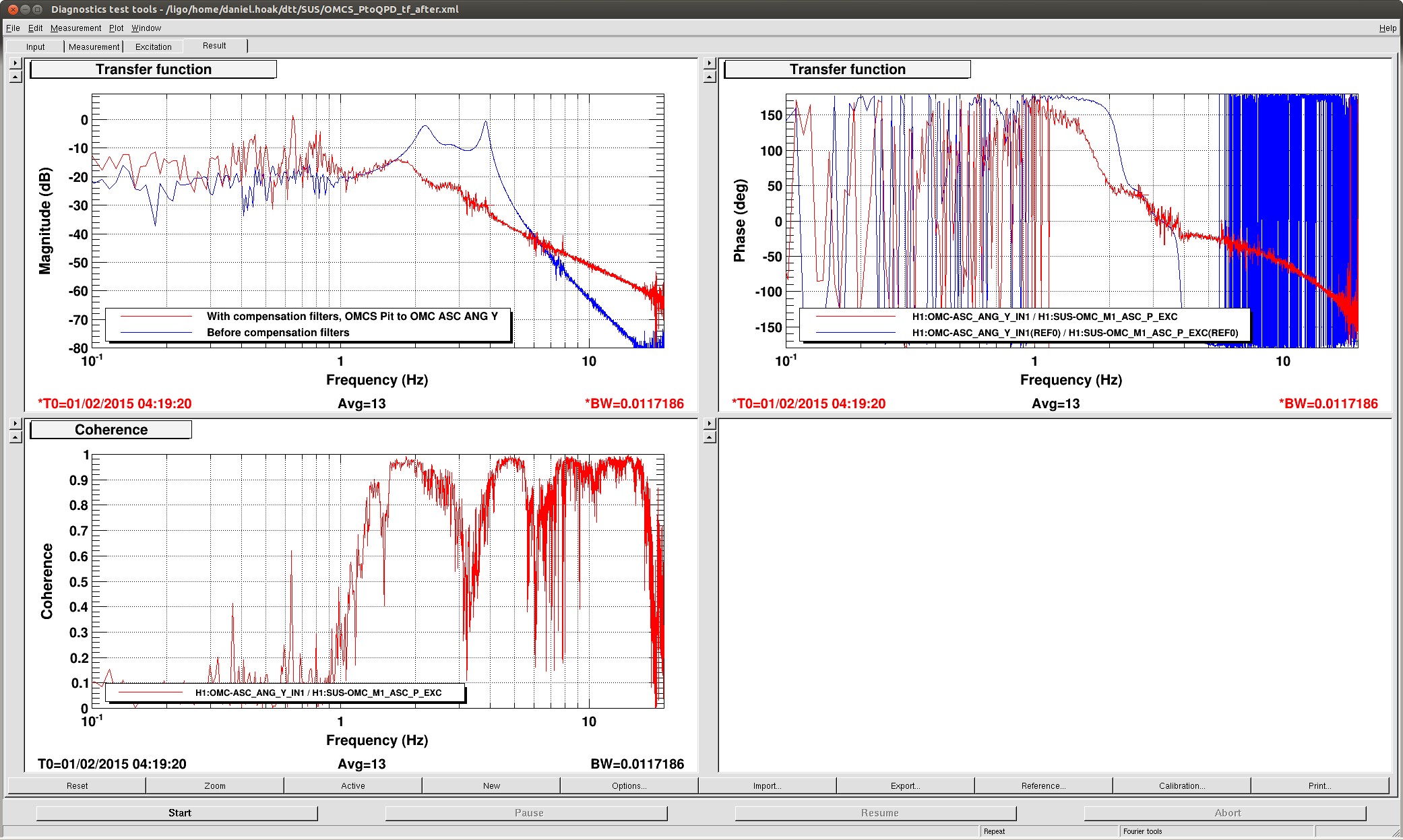
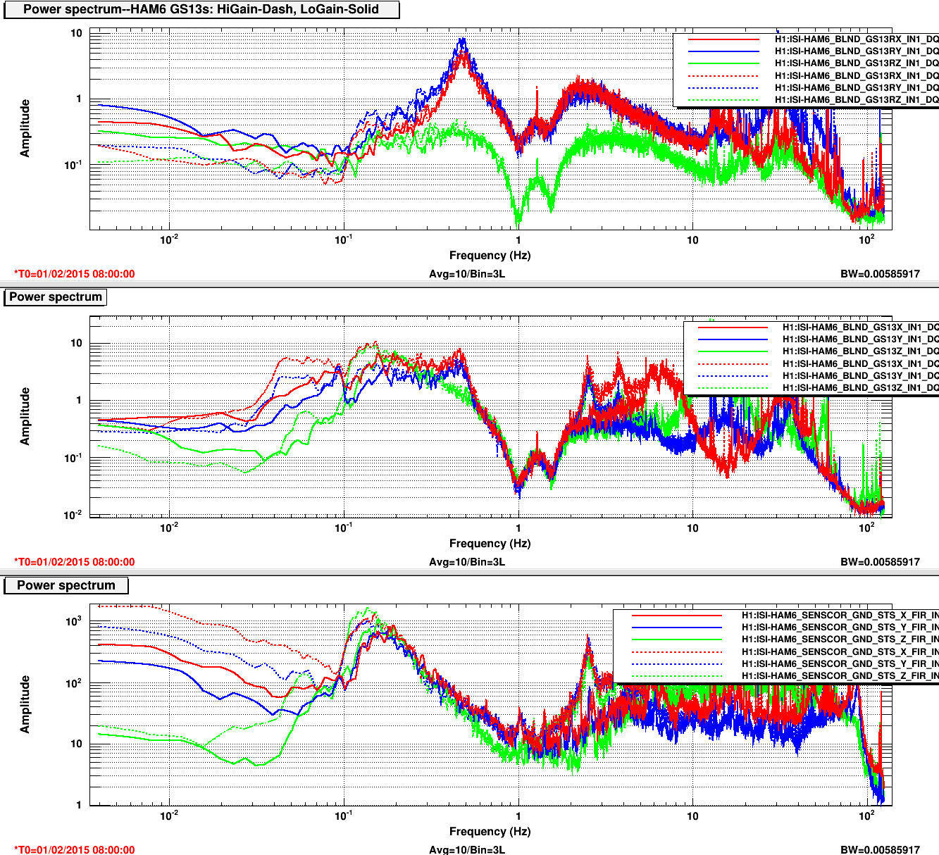
We measured the OMCS --> OMC QPD transfer function with white noise, in the style of the SUS group. The result, for pitch, is the first plot attached. Then, we constructed some filters to remove the peaky features in the TF and make it look more like a damped tip-tilt. The poles and zeros were loaded into the OMCS ASC filter banks, along with a 30Hz cheby low pass. The result is a somewhat bumpy 1/f^2 transfer function above a ~1.7Hz feature that looks like a low-Q resonance; see the before/after comparison in the second plot. The TF is a little more gnarly that we would like, I think we will make some tweaks after measuring the shape of the full OMC alignment loops.
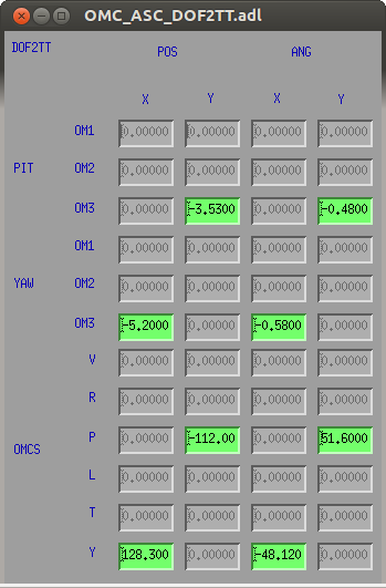
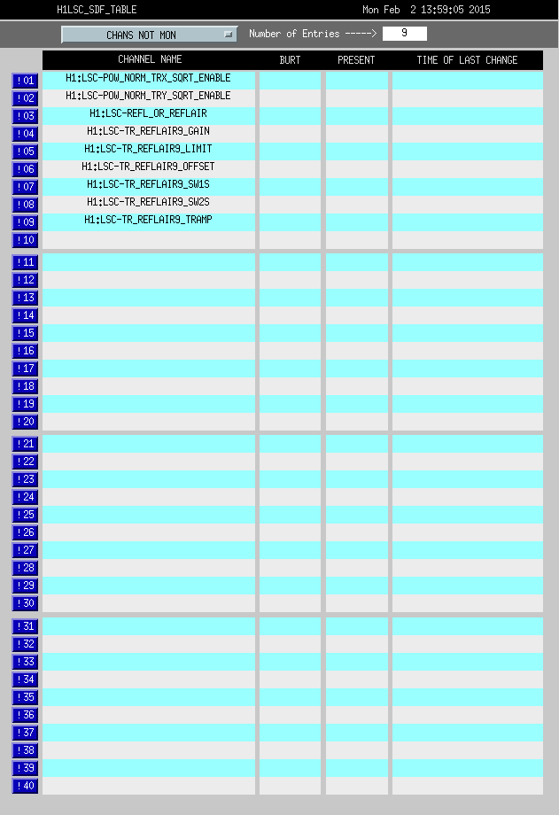
With the new filters for OMCS ASC pitch and yaw we were able to measure an {OM3, OMCS} --> OMC QPD sensing matrix, invert, and closed the OMC alignment loops. A screenshot of the output matrix is attached. Because of the short lever arm from OM3 to the OMC QPDs the control matrix is not very diagonal, this could be a problem. The loops were stable (at least, on a Saturday evening), and we could close the AS WFS DC centering and the OMC alignment loops independently. We found that if we set the gain of the OMC alignment loops too high we would saturate the OMC suspension drive. This could also be a problem for this alignment topology (along with cross-coupling between the OMCS degrees of freedom), depending on how much gain we want with the dither loops. We need to measure the OLTFs, trend the control signals during weekday seismic noise, etc. before we can be confident that this distribution of the control is robust.
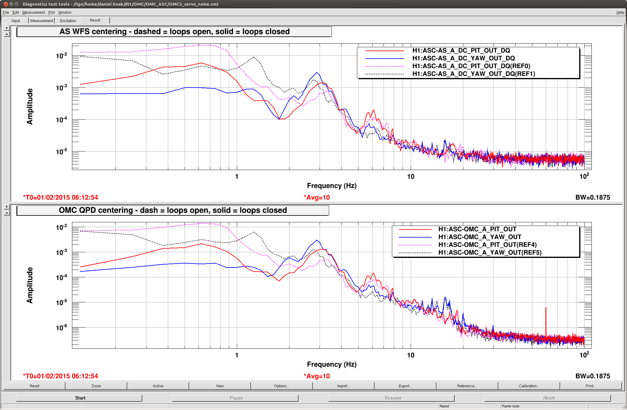
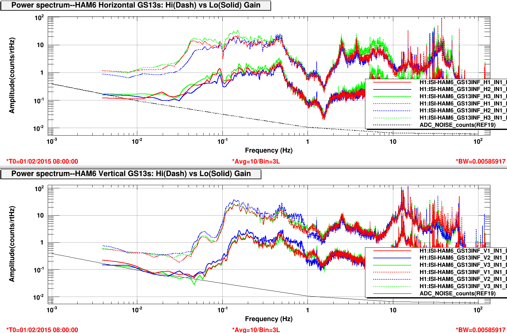
The fourth plot compares the beam jitter on AS WFS A and OMC QPDA, with the loops open and closed. The noise befow 1Hz is suppressed by a factor of ~several. The loops add some noise around 3Hz.

At one point we also tried transitioning at a farther offset. If I remember correcly, the CARM offset was about -25. This also failed.