Kiwamu, Elli, Alexa, Evan, Rana, Daniel, Sheila
Today we were able to reach CARM offsets around 30 pm.
We transitioned DARM to AS45Q, at a CARM offset where sqrt(TRX+TRY) was -7, we then normalized the signal by sqrt(TRX) (with a factor of 0.23). One important step in getting there was to implement the ezca servo that adjusts the ALS DIFF offset to bring AS45Q into the linear range. We are now using that both at a CARM offset of 1 (in SQRT TRX+TRY), and after we transition to the QPDs. We then change the DARM loww pass filter from a 33Hz low pass to a 80 Hz low pass, to get better phase margin since we are no longer saturating the ESD with ALS noise. We did this transition several times sucessfully. As Rana mentioned in alog 16334, we installed an ND1 filter on ASAIR A. Since this we haven't transitioned to RF DARM again (for reasons that seem to be unrelated to the ND filter), so we will need to check the gain before we transition again.
After making this transition, Elli, Kiwamu and Rana worked on the DHARD WFS, which we turned on to reduce the fuctuations in AS DC. This allowed us to go to CARM offsets -25 in sqrt(TRX+TRY), which is about half of the total power we expect in the arms. If you assume that the recyling gain is 30 (we don't really know) it is something like 30 pm. In Refl DC we saw the power drop by about 20%. We saw that the linearized REFL 9 I signal had turned over, and that without linearization the signal had reached the peak. We made a few attempts to transition, and we were able to turn down the gain of the TR CARM signal to 50% of the nominal and turn the REFL 9 signal to what we think the nominal gain should be (-100 in the input matrix). We lost the lock when we turned off the TR CARM signal. Our next plan was to leave the TR CARM engaged with reduced gain, and keep reducing the CARM offset.
However, we have been having a hard time locking in the last few hours. We think that it might help to try transitioning to DARM to RF a little sooner, so that we could use WFS.
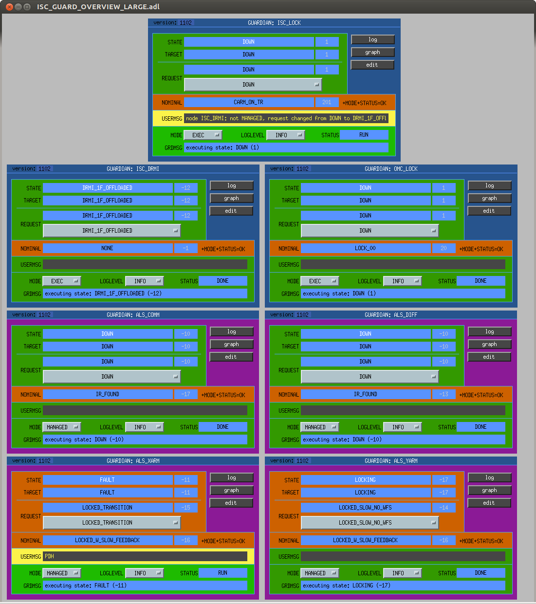
The sequence that was working earlier this afternoon is in guardian up to the RF DARM transition, although this might need to be re-worked. We have added but not tested a state for the DHARD WFS.
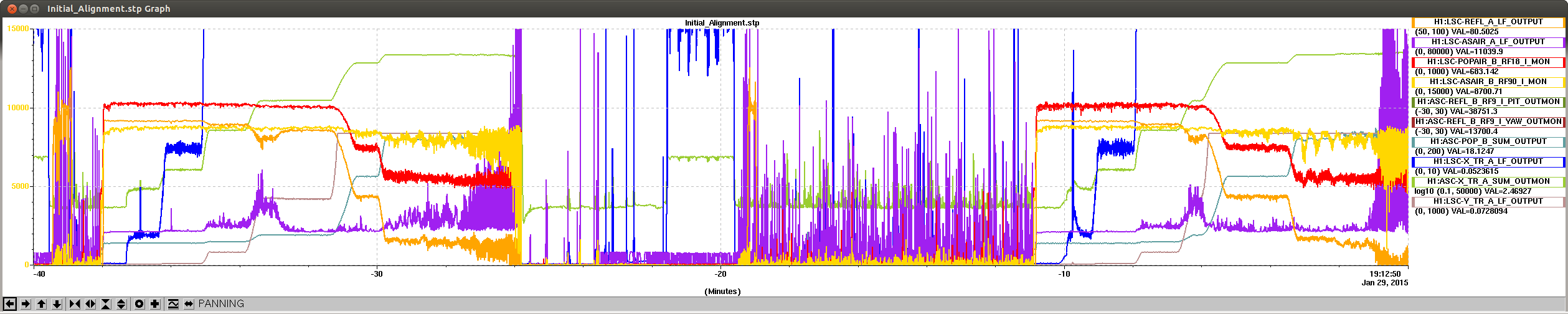
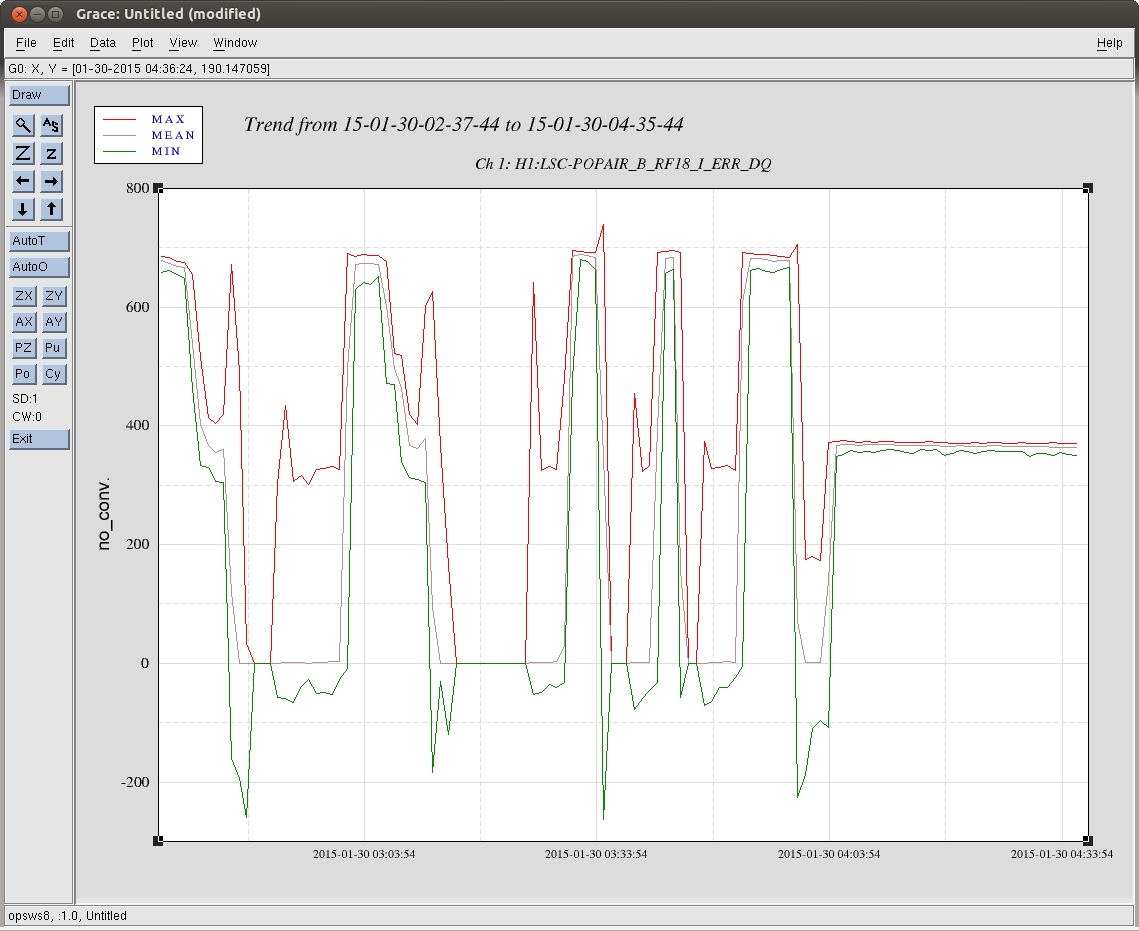
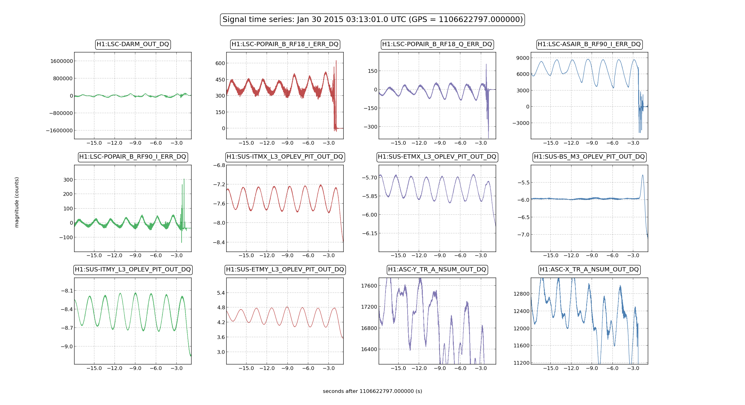
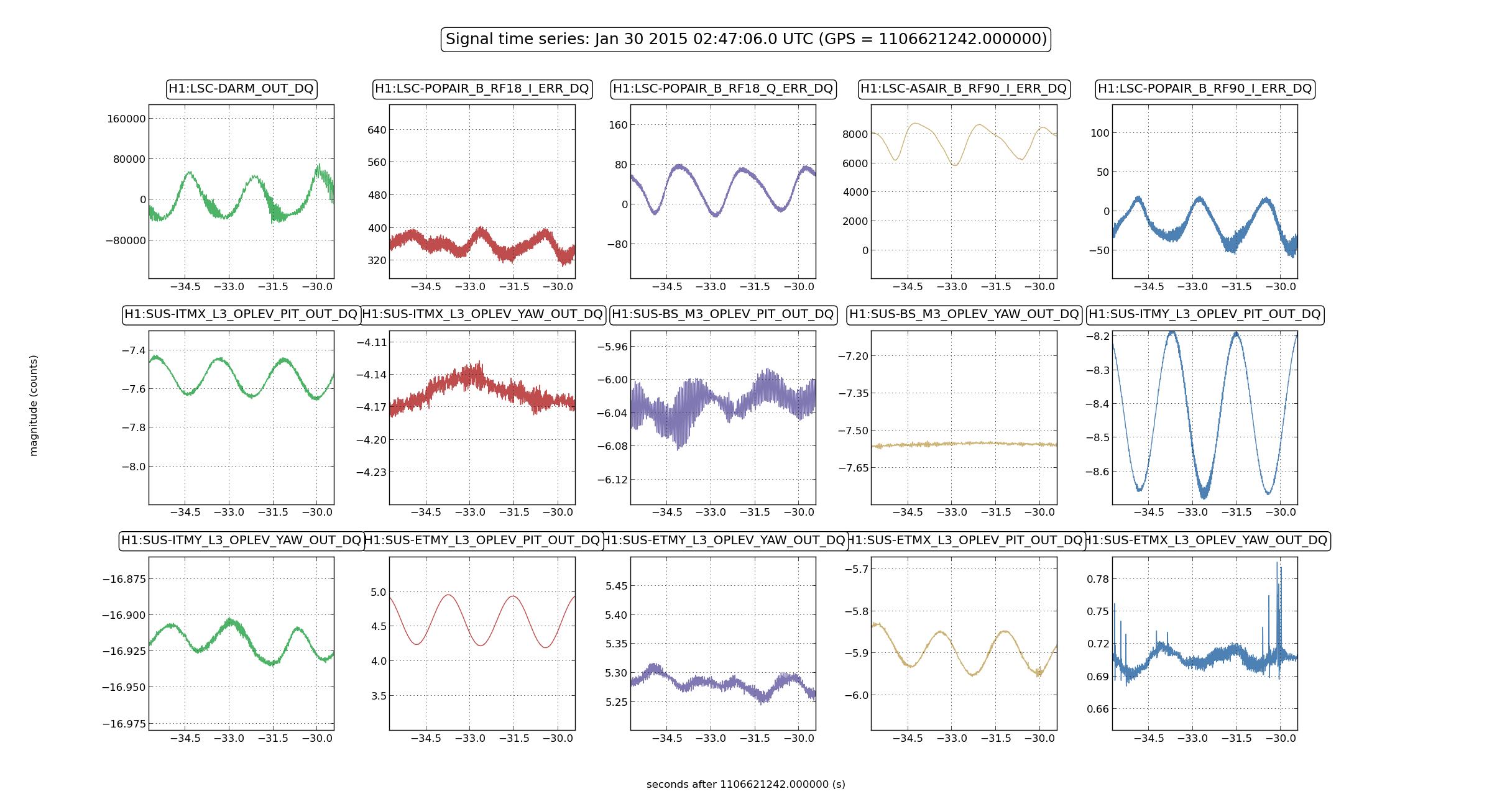
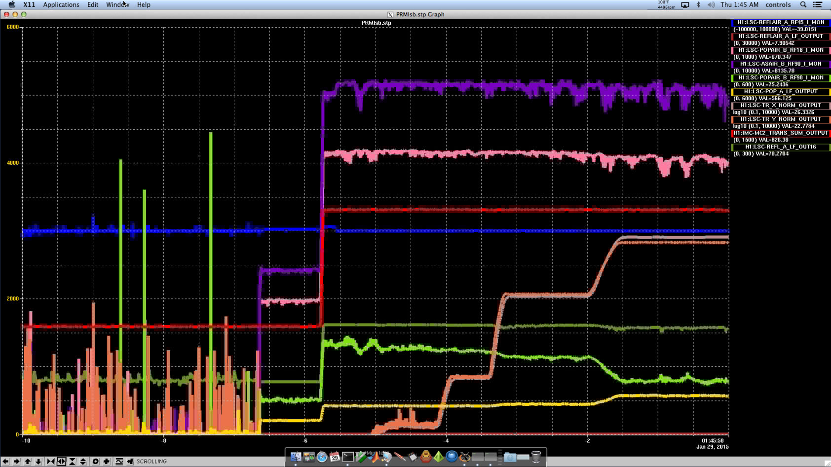
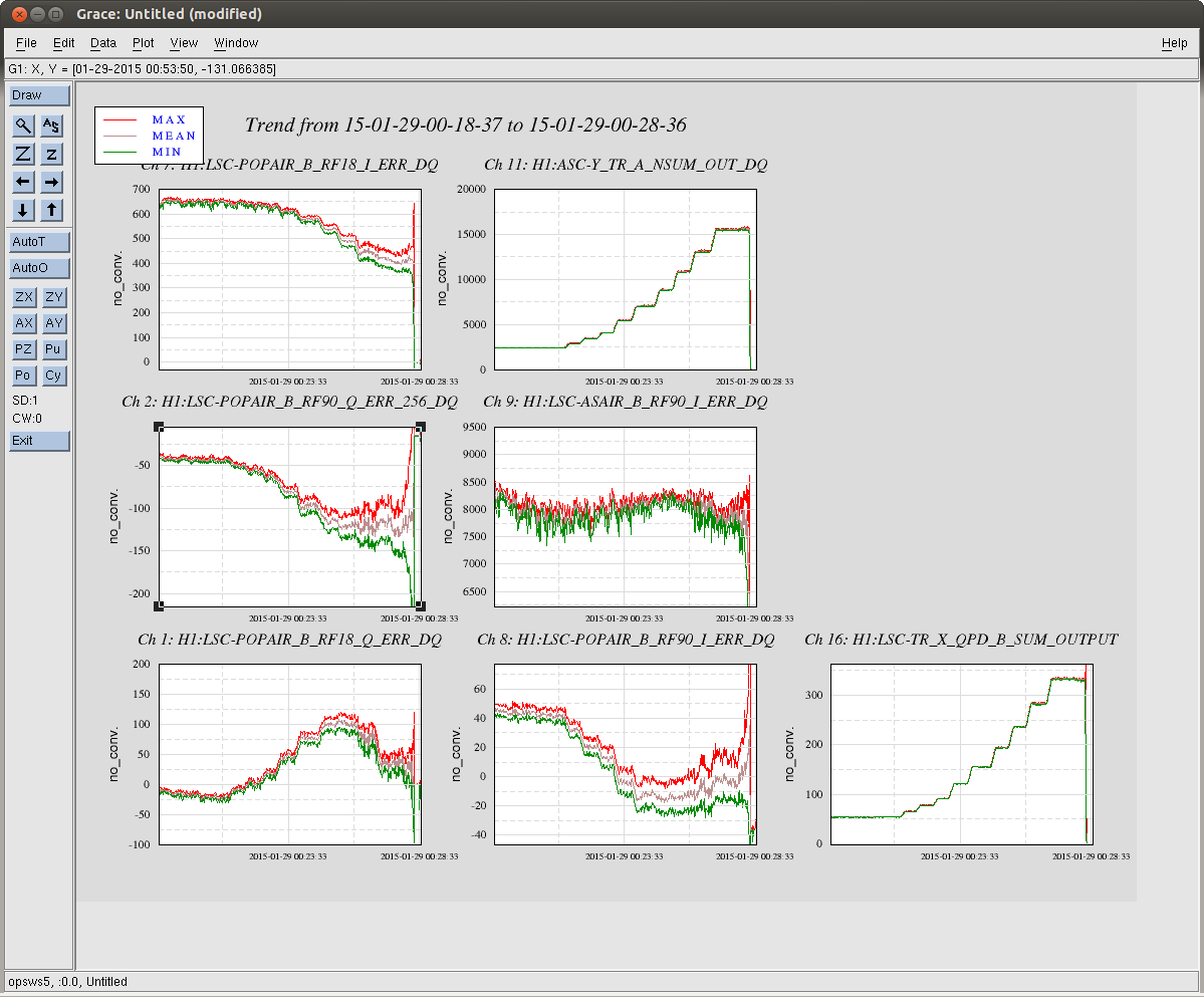
Attached is a screenshot of our striptool durring the sequence, which was all handled by the guardian this time.