Evan, Alexa, Elli, Kiwamu, Rana, Keita, Sheila
We are getting closer.
Today it has been much more reliable and robust for us to get to the state where DARM is controlled on RF. Differences from yesterday that have probably helped with this:
- We have added a new state to the ALS ARM guardian that puts the tidal for the X arm in the transition state once ALS DIFF is locked.
- We realized with remote help from jamie, that we cannot instanstiate a cds utils servo until we are ready to start using it. As soon as we intsansitate it, it will start to integrate. We found this problem using the lock loss tool, and have fixed the ISC_LOCK guardian to do this.
- We are carefully adjusting the ETM alignment by hand in the CHECK_IR state.
- We have addded a 200 Hz low pass to DARM, and we are turning off the 80 Hz low pass after the transition to RF DARM, and removing the 60Hz notch.
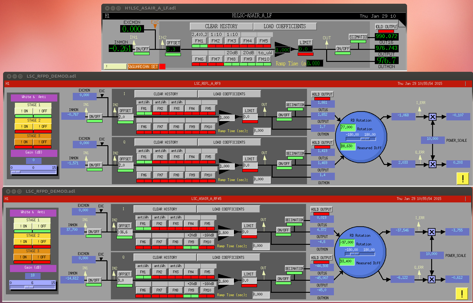
The ISC_LOCK guardian takes us to an offset in TR CARM of 20. There we have been trying to transition to REFL9 I/TRY. We lowered the whitening gain of REFL9I which was saturating the ADC, we now have 0dB whitening gain and no whitening filters. The steps that we have been doing that are not yet in guardian are:
- move CARM TR offset to -25, with ramp time of tens of seconds. At about 2/3 of the way through this ramp we reduced the DARM gain (in the input matrix) from 30 to 20.
- We have often turned of the DHARD WFS at this point, although its not clear that was necessary.
- when we arrive at -25, we adjust the offset in REFL_TR to match the input.
- We add TR_REFL to the input matrix with a gain of -20, and ramp TR CARM down to 0.5. We have been able to go to TR CARM gains of 0.25 stably.
- We noticed at this point that TR CARM still seems to be in charge at DC, so we added a high pass in that path with a zero at 0.1 HZ and a pole at 1 Hz.
- After engaging the high pass we were able to reduce the offset in TR REFL to -6 or so, and to reduce the gain the TR CARM path further.
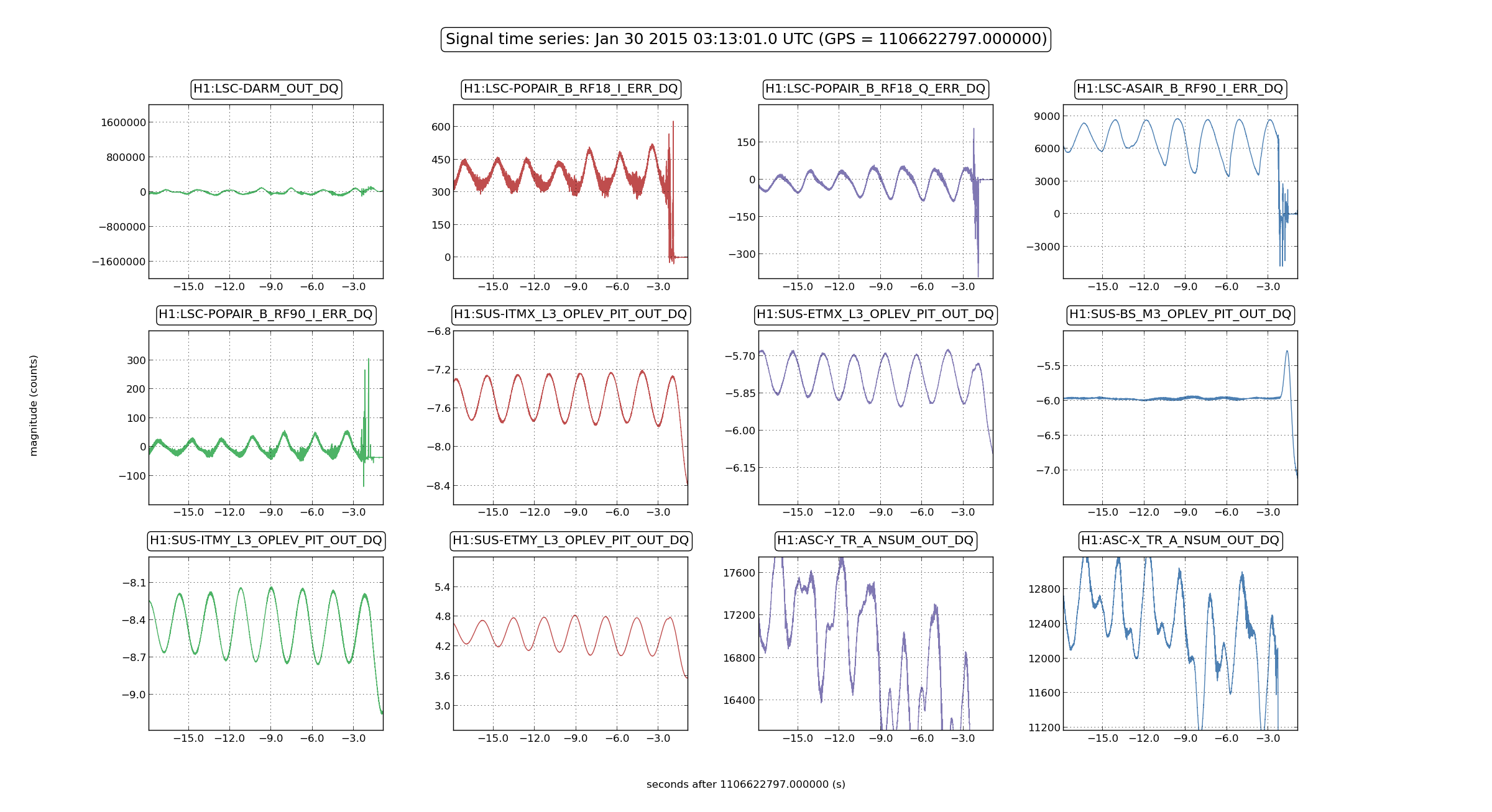
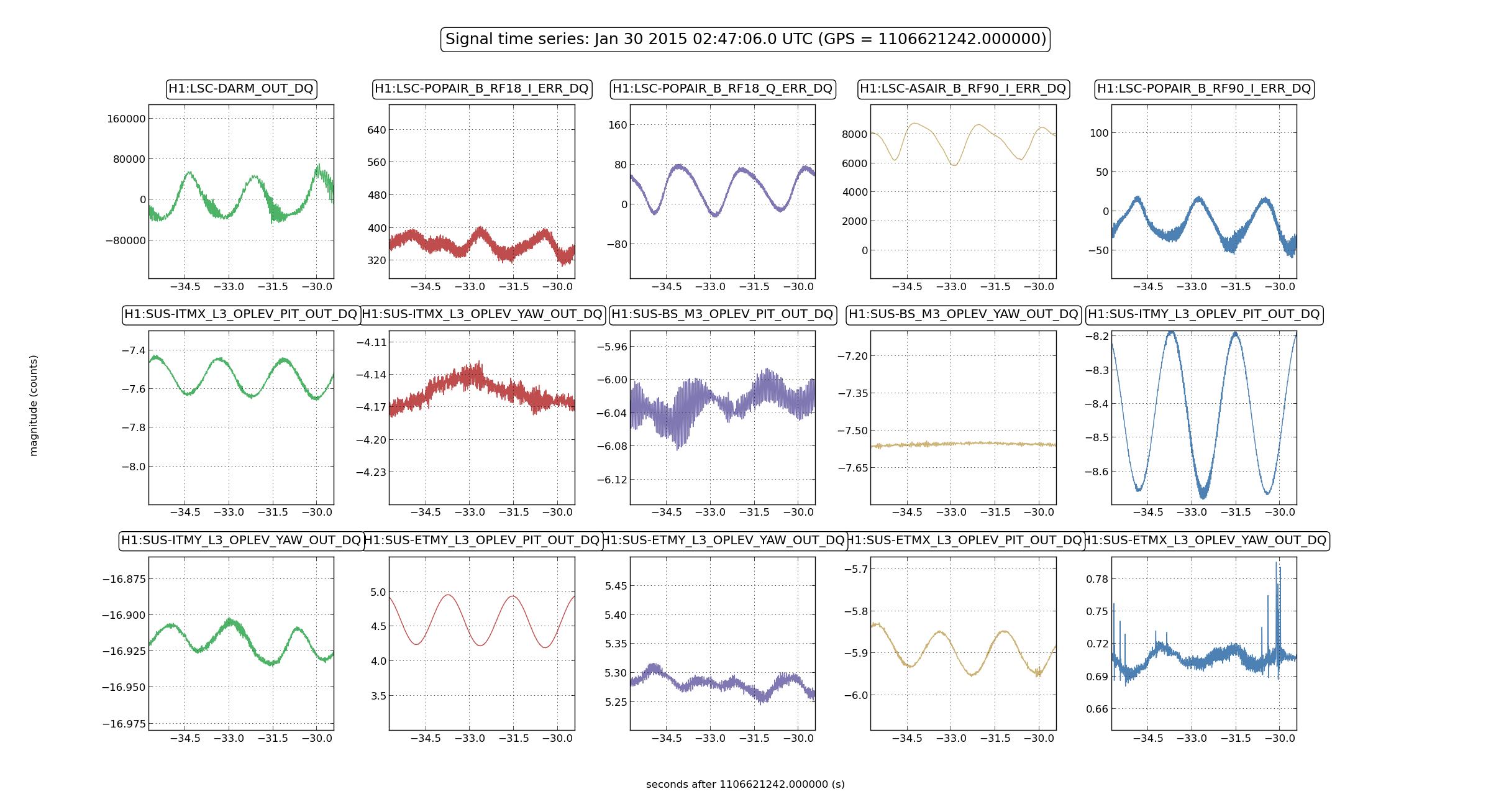
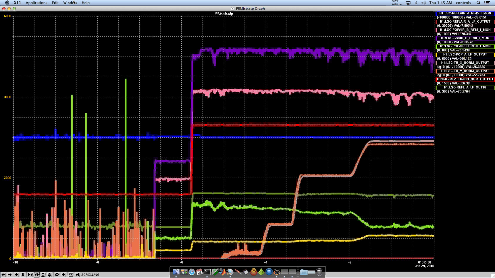
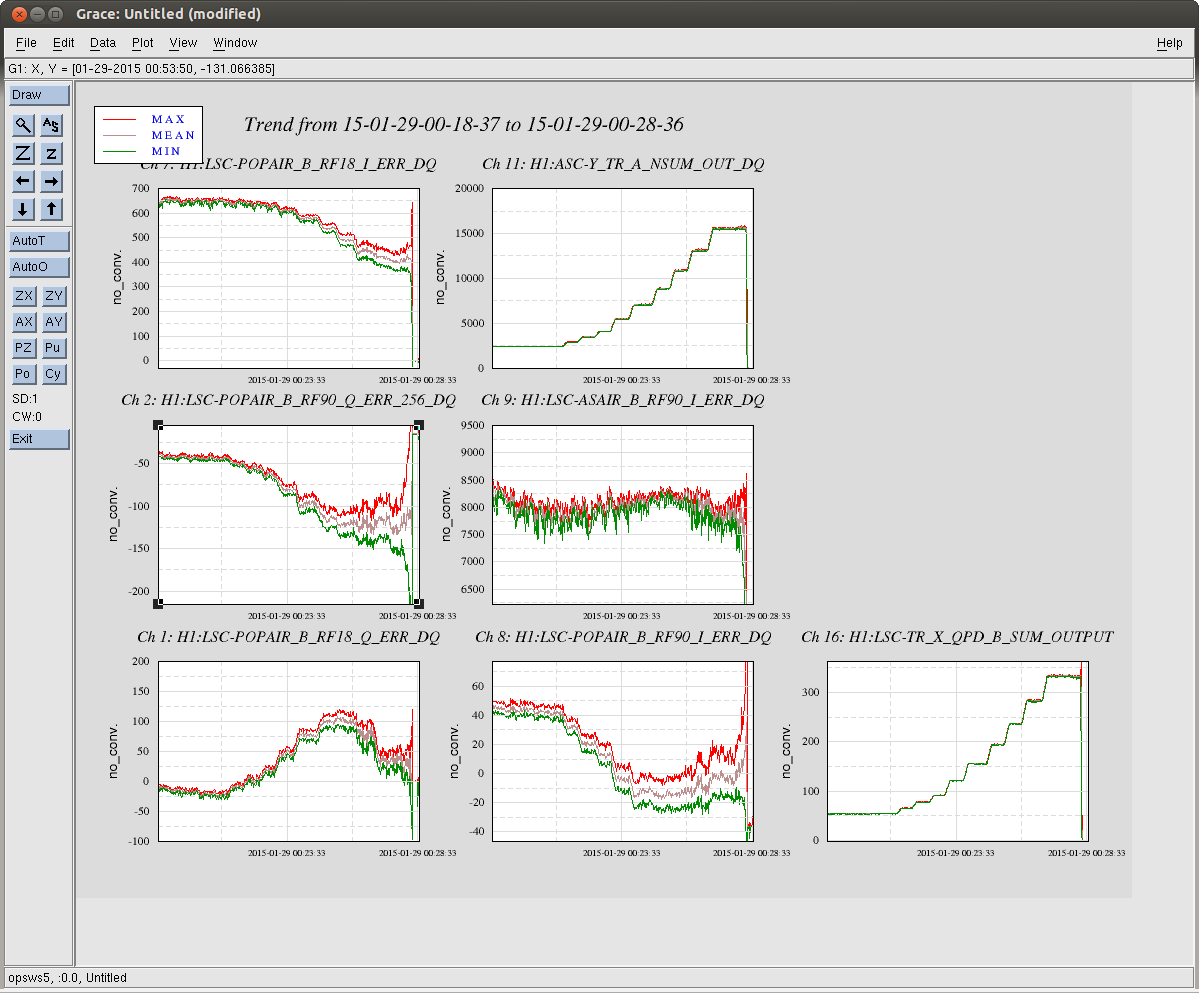
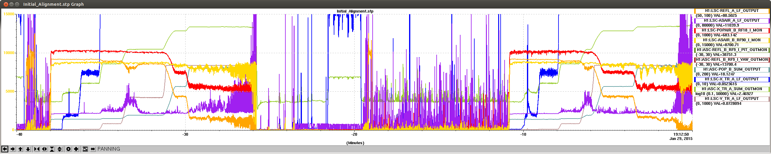
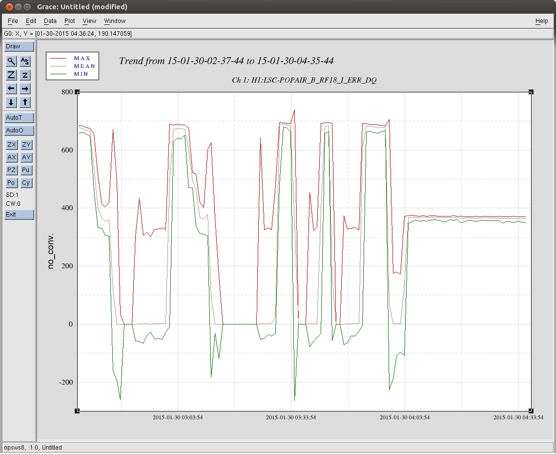
At this point, some kind of oscillation has been starting which eventually blows the lock. Some example times are 2:47:06 UTC and 3:13:01 UTC. The attached striptool shows both of these events. You can see the oscillation in POP18, AS 90, AS DC, and REFL DC. As I've been writing I've been letting the guardian try to lock on its own, it has lost the lock twice in the REDUCE_CARM_OFFSET_MORE state, I think this is because the DIFF offset wasn't adjusted well. I've extended the time that the servo runs before this step.
I've left DRMI locked, with the arms misaligned for seismic people.
This DRMI lock stretch Sheila's left us began undisturbed starting ~04:05 UTC.
Here're some relevant conditions of the IFO.
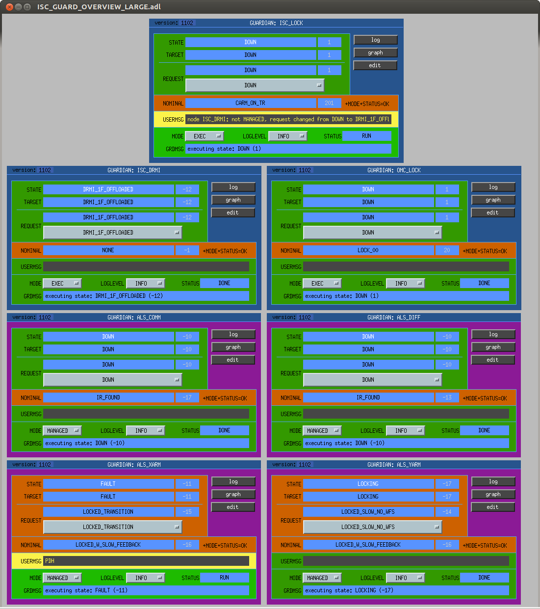
DRMI is Guardian is in requested state DRMI_1F_OFFLOADED.
IM4, PR3, BS, and SR3 alignments must have been tweaked recently, as their alignments are not saved, according the Guardian.
Corner station WFS are OFF
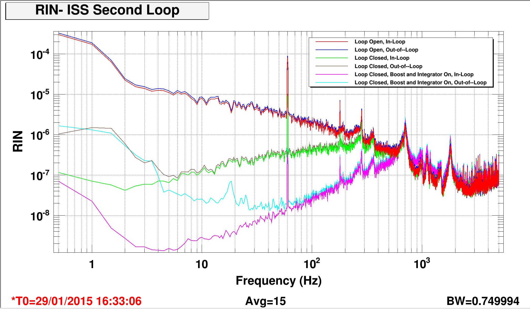
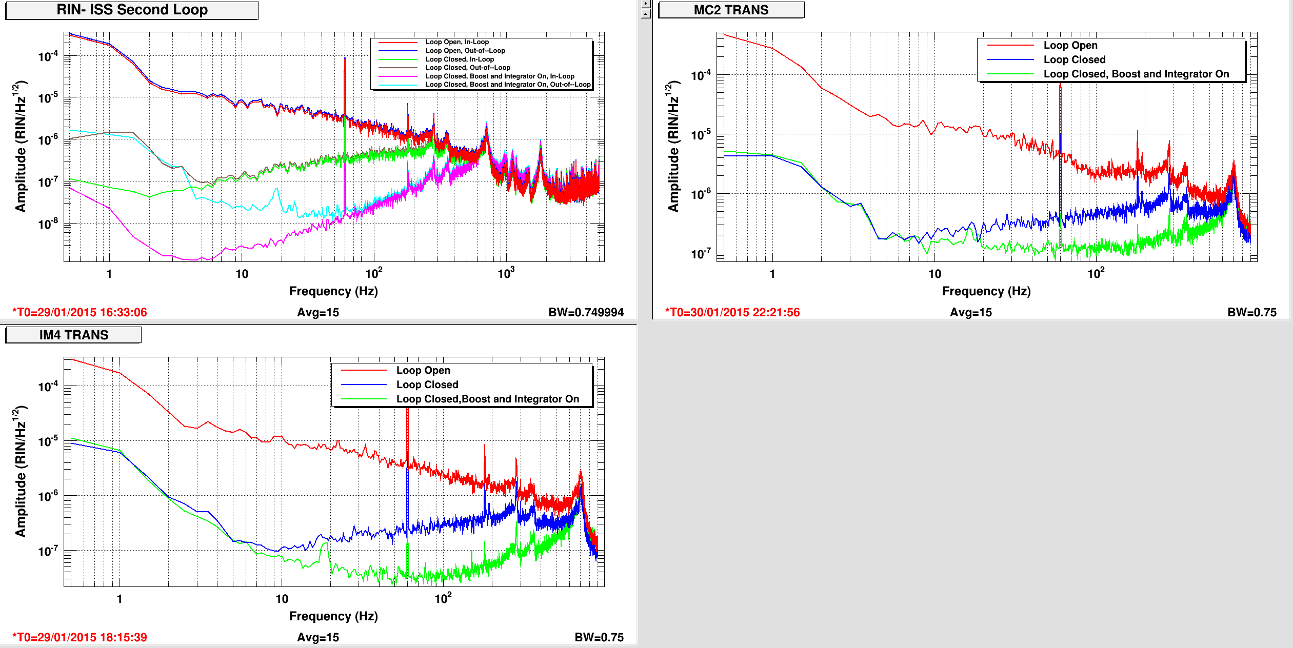
ISS Second Loop is OFF
Wind is low, <5 [mph]
Seismic Env.:
Band Limit [um/s] (12-hour trend)
0.03 - 0.1 = 4e-1 (steady)
0.1 - 0.3 = 2e-1 (on its way down)
0.3 - 1.0 = 3e-2 (steady)
1.0 - 3.0 = 1e-1 (Hanford is on shift and loud)
3.0 - 10 = 3e-1 (steady)
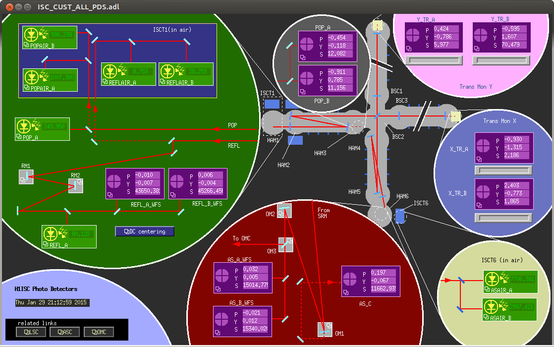
Optical levers well centered (about ~5-7 [urad] off center in P&Y) for BS, ITMX, and PR3. ITMY and SR3 is a little further off centered (about 15-17 [urad] off center).
BS Optical Lever Damping in P and Y is ON, no other Optical Lever Damping is ON.
All corner station HEPIs are ON, position-sensor only, locked to the ground, ~4 [Hz] UGFs. ALL DOF isolation loops closed, including AC coupled HP and VP. BSC HEPIs have Z sensor correction ON.
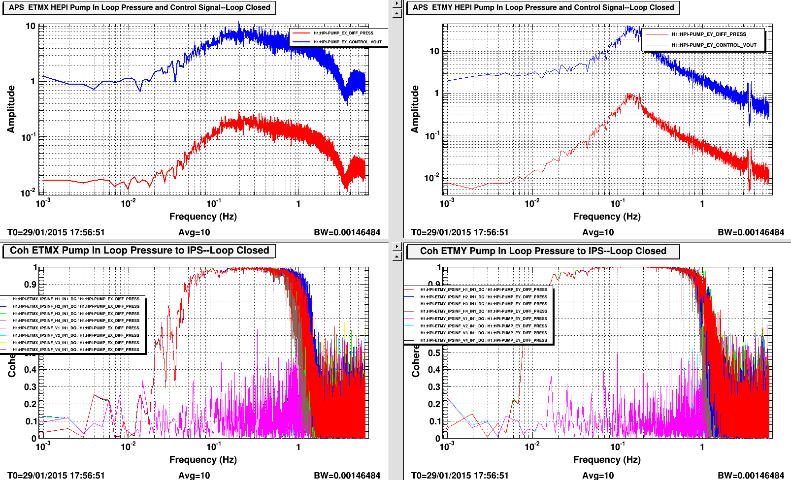
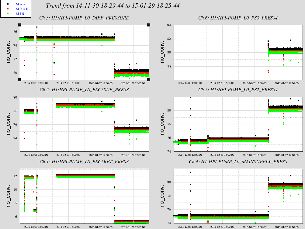
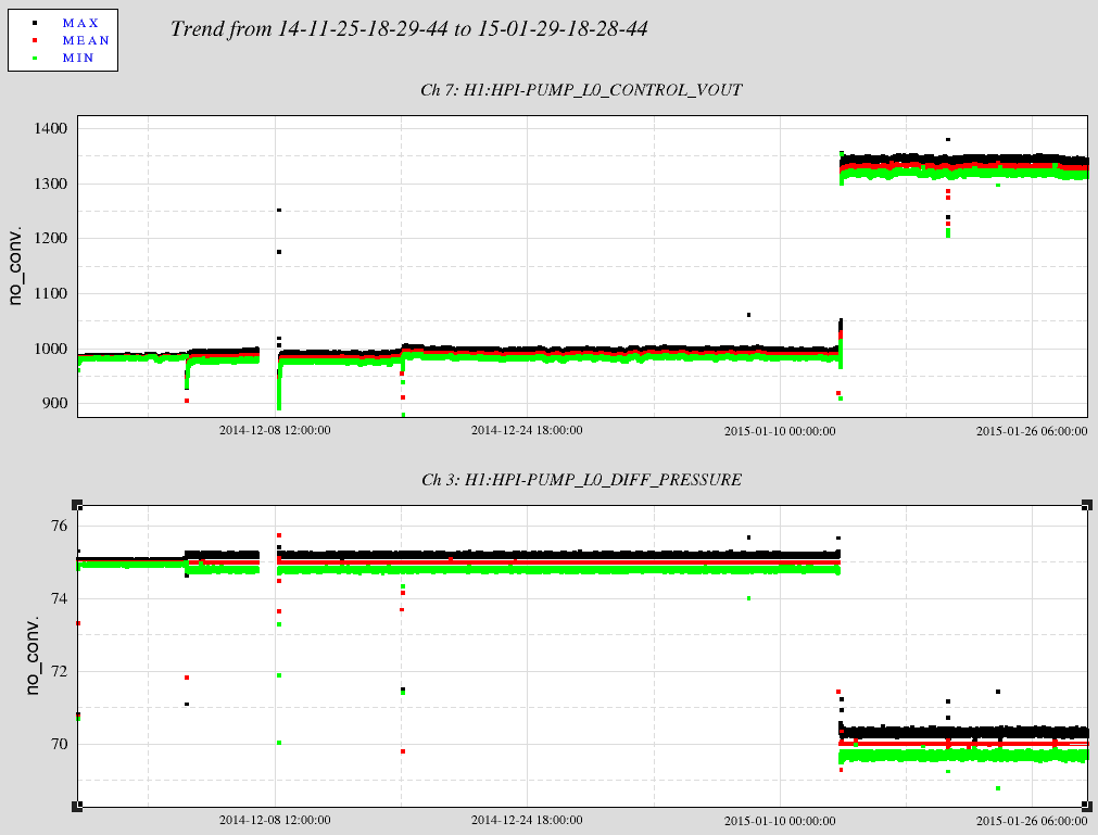
Corner Station HEPI Pump Servo is ON.
All HAM-ISIs running ~30 [Hz] isolation loops, sensors blended with 01_28 filters (including HAM3!), sensor correction ON in X, Y, and Z. ALL DOF isolation loops closed. GS13s are in HIGH gain mode, with DeWhitening filters OFF.
All BSC-ISIs running ~30 [Hz] isolation loops, sensors blended with
ST1 X&Y 45mHz, Z 90mHz, RX&RY 250a*250b, RZ 750mHz
ST2 X&Y 250mHz, Z, RX,RY,RZ T750mHz
ITMs: ST1 RZ isolation loops are NOT closed, all other DOFs are closed
ST2 only X&Y isolation loops are closed
BS: ST1 RZ isolation loops are NOT closed, all other DOFs are closed
All ST2 isolation loops are OFF
ITM GS13s are in HIGH gain mode, with DeWhitening filters OFF.
All relevant SUS happily damped.
Keita, Alexa, Sheila
The osciallation that was breaking the lock last night was at about 0.45 Hz, and shows up in all the quad oplev pitch signals. It looks like the soft mode in both arms, but the oscialltion in the two arms are not in phase with each other. There is some of this noise showing up in DARM, but not in the other LSC out channels, in the BS, PR3 or SR3 signals until after the lockloss
This shows up on the ITMs, and we are not actuating on the ITMs. This is strange, but one thing that we would like to try is using lower power.