Kiwamu, Elli, Alexa, Evan, Rana, Daniel, Sheila
Today we were able to reach CARM offsets around 30 pm.
We transitioned DARM to AS45Q, at a CARM offset where sqrt(TRX+TRY) was -7, we then normalized the signal by sqrt(TRX) (with a factor of 0.23). One important step in getting there was to implement the ezca servo that adjusts the ALS DIFF offset to bring AS45Q into the linear range. We are now using that both at a CARM offset of 1 (in SQRT TRX+TRY), and after we transition to the QPDs. We then change the DARM loww pass filter from a 33Hz low pass to a 80 Hz low pass, to get better phase margin since we are no longer saturating the ESD with ALS noise. We did this transition several times sucessfully. As Rana mentioned in alog 16334, we installed an ND1 filter on ASAIR A. Since this we haven't transitioned to RF DARM again (for reasons that seem to be unrelated to the ND filter), so we will need to check the gain before we transition again.
After making this transition, Elli, Kiwamu and Rana worked on the DHARD WFS, which we turned on to reduce the fuctuations in AS DC. This allowed us to go to CARM offsets -25 in sqrt(TRX+TRY), which is about half of the total power we expect in the arms. If you assume that the recyling gain is 30 (we don't really know) it is something like 30 pm. In Refl DC we saw the power drop by about 20%. We saw that the linearized REFL 9 I signal had turned over, and that without linearization the signal had reached the peak. We made a few attempts to transition, and we were able to turn down the gain of the TR CARM signal to 50% of the nominal and turn the REFL 9 signal to what we think the nominal gain should be (-100 in the input matrix). We lost the lock when we turned off the TR CARM signal. Our next plan was to leave the TR CARM engaged with reduced gain, and keep reducing the CARM offset.
However, we have been having a hard time locking in the last few hours. We think that it might help to try transitioning to DARM to RF a little sooner, so that we could use WFS.
The sequence that was working earlier this afternoon is in guardian up to the RF DARM transition, although this might need to be re-worked. We have added but not tested a state for the DHARD WFS.
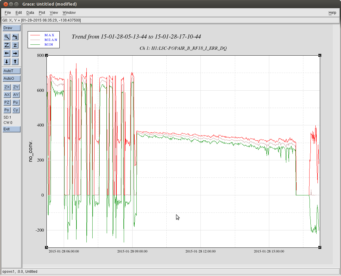
Attached is a screenshot of our striptool durring the sequence, which was all handled by the guardian this time.
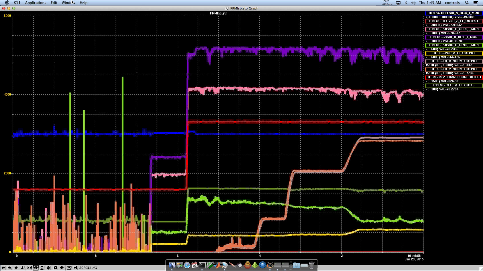
As we were about to leave we had a nice stable lock. We were able to transition to RF DARM again at -7.0 cts CARM offset after having adjusted for the ND filters. We now have a +20dB filter in ASAIR_RF45Q, and the input matrix is now 25. We turned on FM4(z4^2:p1^2) in DARM loop which significantly helped the DARM noise. We then proceeded to adjust the CARM offset to -20 cnts. At this point we transitioned TR_RELF9 to 100% with TR CARM at 50%. We were able to reduce the CARM offset to zero, but this only lasted for about a second or so. We never fully turned off TR CARM, but we think it has a zero slope here since we are at zero offset. More tomorrow when we are awake ....
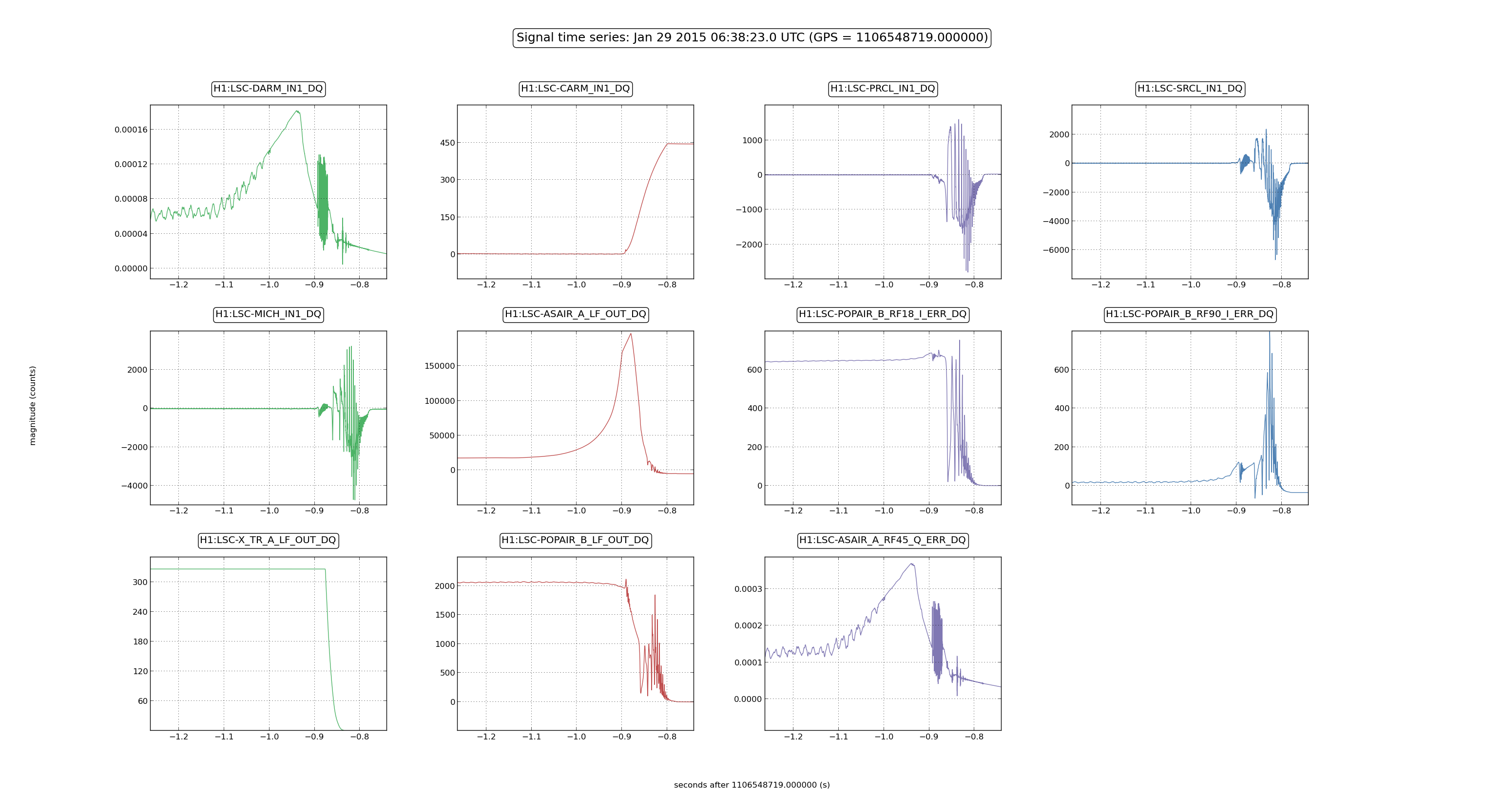
Lock loss time: 09:58:40 UTC Jan 29th
Great work!
Assuming I am looking at the right lock attempt, (data attached starting at 09:48:00 UTC) it seems that REFL DC is only ~30% less than at the beginning of the sequence when you transition to RF. There should be room to get closer.

P.S: For comparison, trend of powers with "lossy" arms is here. The build up in the arms for same relative REFL DC power was about a factor of 3 lower (by eye numbers).

Daniel and Rana have mentioned that optical torques may become significant as we come in to resonance.
Summary
For 10 mm of miscentering and 46 kW of circulating arm power (at 0 pm of CARM offset), we get a torque of 3×10⁻⁶ N m. I estimate the stiffness constants of each pendulum to be 4.9 N m for pitch and 6.5 N m for yaw (a better estimate could be made using the actual suspension models). This means that the static misalignments induced by the radiation torque could be as large as 1 μrad. The attached code computes the torsional stiffnesses of the pendula.
Details
- For 8 W incident on the IFO with the PRM misaligned, we expect 0.12 W incident on each arm. Assuming an arm gain of 283 W/W, that gives 34 W of circulating power.
- From LHO#15390, with the IFO locked we expect a buildup of 1350 W/W compared to the PRM-misaligned single-arm case. That gives 46 kW of optical power.
- The torsional stiffness of the pendulum can be found by computing the moment of inertia of the test mass for pitch and yaw rotations. Combined with modeled torsional frequencies, the stiffness is given approximately by κ = ω2 I.
As a next step, we might also consider the stiffness of the optical springs using, e.g., eqs. 31 in the paper by Sidles and Sigg. At 46 kW of circulating power, we get 15 N m for the major mode and −0.6 N m for the minor mode.
[Edit: Also, Kiwamu has pointed out an error in the expression for the moment of inertia for the test masses. This has been fixed in this entry and in the attached code.]

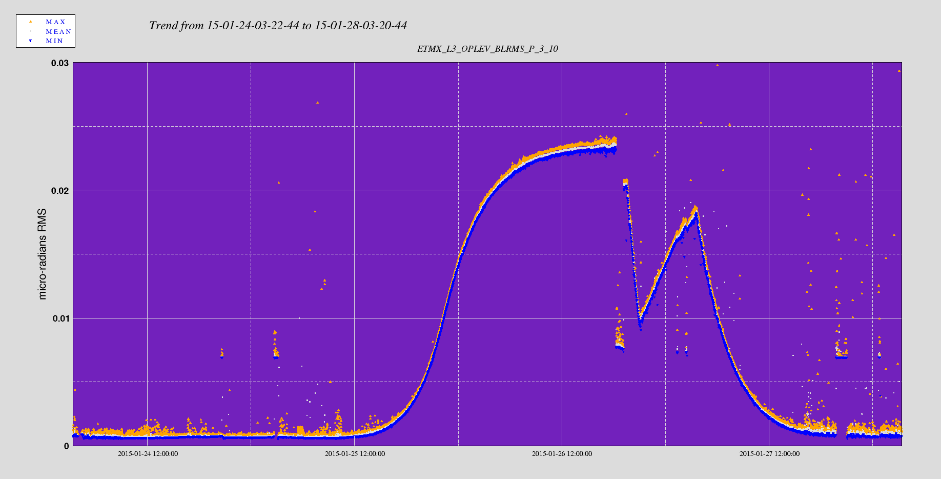
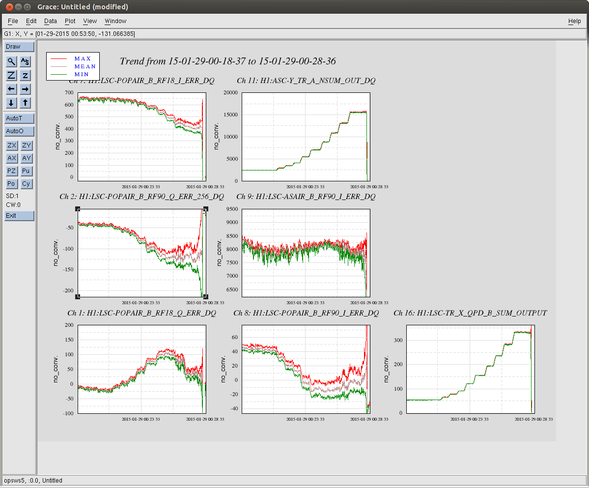
Here are some oplev trends from last night's final lock attempt.
The drop in the buildup of POP18 seems correlated with a drift in ETMX pitch (0.3 μrad), and to a lesser extent BS pitch (0.2 μrad), SR3 pitch (0.4 μrad) and ITMY pitch (0.2 μrad). There may also be some drift in PR3 yaw and pitch (≈0.1 μrad). All of these drifts happen on time scales much slower than the change in TRX buildup, which supports the idea that these are thermal drifts induced, e.g., by wire heating.
For the record here are some lock loss times from last night:
Early in the evening we were trying to transition DARM from ALS_DIFF to ASAIR_A_RF45_Q and the lock dropped at the following times:
Jan 28 20:46:40 UTC, Jan 28 21:06:32 UTC, Jan 28 21:06:17 UTC, Jan 28 22:55:00 UTC.
Speculating from the lock loss plots, we think that DARM noise causes a big spike in light leaking out of the AS port. This causes the power on the LSC-TR_X/Y_QPDs controlling CARM to fluctatue enough that CARM drops lock. Running the ASAIR centering servo should help minimise big spikes at ASAIR_A_LF. Once we were able to transition DARM to RF this type of lock loss stopped happening.
-----------------------
Here are some lock losses from after the transition DARM to RF. The cause of these lock losses remained unclear. MICH, PRCL and SRCL were ringing up signals at various frequencies (4Hz-20Hz) but this changed from lock loss to lock loss. Again there are big spikes in ASAIR_A_LF right before the lock loss. ETMy alignment needed frequent touching up.
Jan 29 00:28:31 UTC, Jan 29 00:49:41 UTC, Jan 29 05:34:23 UTC.
--------------------
Later in the evening we were having a hard time locking. Again we were loosing lock before DARM transition to RF. Again there are big spikes in ASAIR_A_LF, probably caused by DARM motion.
Jan 29 07:35:25 UTC, Jan 29 07:35:25 UTC, Jan 29 08:24:26 UTC, Jan 29 08:40:40 UTC
Here is a screen shot of the CARM offset reduction from earlier in the evening, when the alingment must hve been slightly better. Although we didn't reduce the CARM offset, and were locked on TR CARM, we had a recylcing gain of about 10.2. Also, some of the signal from POP18 and POP90 is rotated into the Q phase as CARM offset is reduced.
Peter, Matt, Lisa

For the records, we had this theory that if the f_1 was tuned such as to make the 2f_1 resonant in the arms, the beat between the 2f_1 and the carrier in the recycling cavity could be responsible for the decay in POP18.
Looking in the L1/H1 logs and MEDM screens, we arrived at the conclusion that in H1, given the arm length of 3994.4704 m and f_1  = 9.100230 MHz, the offset from resonance for the 2f_1 should be 380 Hz.
In L1 the offset for the 2f_1 from resonance is 500 Hz (reported here), as nominal.