J. Kissel, B. Lantz, H. Radkins
Hugh and I, with the remote advice from Brian, have been investigating the coupling between HEPI differential pressure noise and HEPI platform motion (see preliminary studies in LHO aLOGs 16231 and 16309). In summary, the coupling is smattered between every chambers DOFs, limiting the performance between 0.02 and 2 [Hz]. There's no pattern as to how this coupling occurs except that the coherence for a given DOF happens in a similar frequency band in all chambers. All chambers show differential pressure moderate coherence to HP, but we're still working on estimating the transfer functions between this "pringle" mode and any translations / rotations to assess this impact. Further, we still have set up any successful long stretches of IFO / WFS data for the DRMI, so this pressure noise' impact can't yet be assessed. However, for now, I continue under the assumption that *any* low frequency improvement, especially to RZ / YAW, will improve the relative angular fluctuations of the IFO and stabilize optical gains, etc.
Hugh has already revealed the punchline: this morning's pump-servo OFF data shows that the problem is entirely because is of noise on differential pressure sensor. I'll attach a comment with complete set of plots for proof in a bit.
Further discussion on the noise as it stands with the pump servo (i.e. ON), based on the attached plots, which include
-
ASDs of all Cartesian (plus pringle) DOFs' L4Cs -- out-of-loop witness sensors -- compared against the differential pressure and the expected sensor noise**,
-
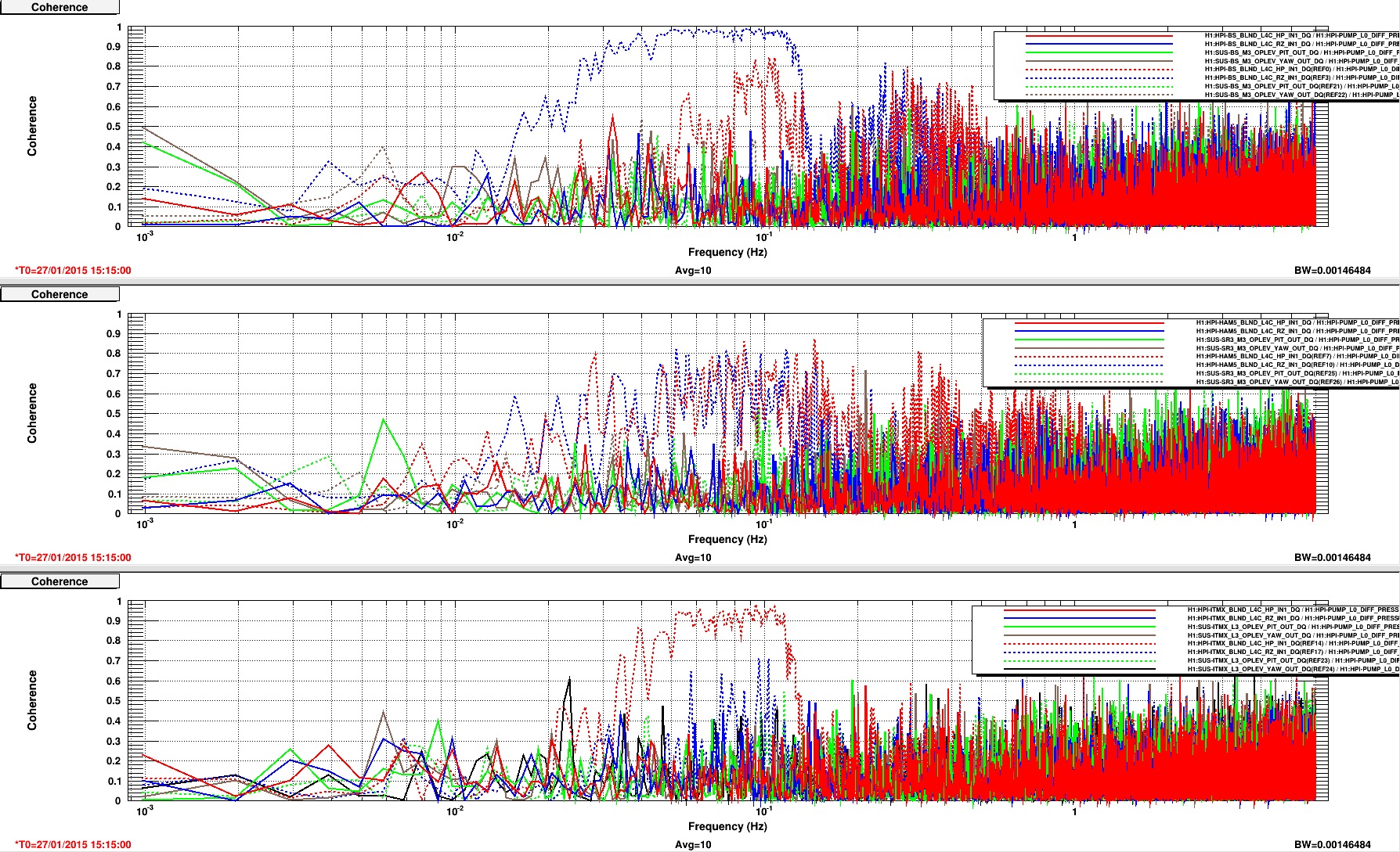
Coherence between all Cartesian (plus pringle) DOFs and the differential pressure,
-
ASDs and RMS of Colocated Actuator Drive signals, compared against the differential pressure and the 2 [hr] mean, DC value of each signal,
is below. I post all of these discussion points for future reference and design considerations to show how nastily and diversely imposing sensor noise on the pump servo imposes the platform motion. But mostly, because I sorted through a TON of data and plots to make these conclusions, before we knew the source of the problem.
** For the HEPI L4C ASDs, I plot the *raw* sensor noise because (a) I'm trying to cram as much information on as few plots as possible, and (b) the scale factors for both the IPS and L4Cs are the same for each DOF, and are all between 0.3 and 1.1, so the estimation estimation is off by at most a factor of three. Mostly it's there just to guide the eye, as a primitive noise budget.
(1) Krishna (before coherence between all DOFs and chambers was fully flushed out), suspected that because we now run Z sensor correction is on HEPI, the extra drive force meant excess pressure noise coupling. However, compared to 23e3 [ct_{rms}] range, the Vertical RMS of 5 [ct_{rms}] is peanuts. Further discussion of DC / mean requested drive is below.
(2) Brian suspected that the passive filtering system, the accumulating bladders might not be operating at their nominal air pressure. However, pump 8's (out of 12 for the corner) bladder pressure was checked last week, and was within spec. There're still lots lots to check, but Hugh suspects they're also OK.
(3) I suspect the PID controller for the servo is likely not well-tuned for new differential pressure sensing, suggesting we need to remeasure plant (which could mean significant down time for the IFO). There's been some discussion offline in the SEI group as to how we should systematically characterize the pump servo plant, given there's no "fast" excitation point in the pump servo make a tranditional frequency-response transfer function difficult (see SEI aLOGs 684 and 686). For now, we suspect we can do a sufficient characterization with simple steps using the existing EPICs infrastructure. Characterization to-date (though very early on in aLIGO) was also made by step response (see E1100508), but the assumptions about the plant don't seem sound in retrospect, and were done when the pressure was still on an absolute "single ended" readback.
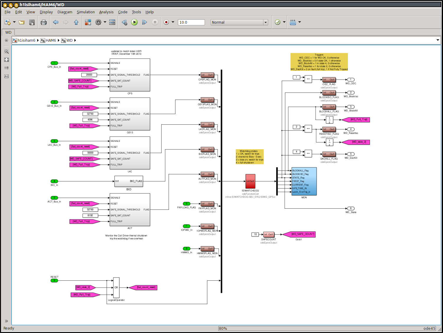
- Brian's "Allowable Pump Servo Noise" defined in T1100198, but contains a LOT of assumptions. One of which is that the open loop gain transfer function of the feed back loops is "100 at low frequency." As such, Brian suggests, if the HEPI feedback loops are gain limited, try adding some boost at these frequencies to suppress the noise. However, I argue, with Hugh's recent redesign of the controller (see LHO aLOG 15308, the relevant attachment re-attached here), RZ Loops for example have *plenty* of gain, upwards of 3000 - 4000 at 0.1 [Hz], typically asymptoting to a few million a DC. This is far more than Brian assumed, so I thing we're alright in the gain department. Regrettably, the differential pump pressure is an EPICs channel, so I can't get an ASD of the performance above ~8 [Hz], but I'll post more on that in the future comment.
- Differential Pressure Noise supposedly coupling increases with actuator force request, but I've not found this to be true empirically. Check out the table below. Colors of the text help indicate which requested DC offsets are small, and which are large (dark green is smallest, then light green, gold, orange, with bright red is largest, in bins of 50 [micro-whatevers] and anything higher than 200 [micro-whatevers] is marked as bright red). Cells shaded in gray show coherence between the differential pressure and the HEPI L4Cs.
There is no discernable pattern:
|
|
X [um] |
Y [um] |
Z [um] |
RX [urad] |
RY [urad] |
RZ [urad] |
HP ["um"] |
VP ["um"] |
|
HAM2 |
24
|
-159
|
-142
|
27
|
160
|
-21
|
185
|
6
|
|
HAM3 |
3
|
109
|
-105
|
-24
|
-25
|
-124
|
131
|
93
|
|
HAM4 |
169
|
-124
|
-45
|
11
|
4
|
-78
|
141
|
-14
|
|
HAM5 |
47
|
-103
|
-17
|
97
|
-13
|
13
|
71
|
-19
|
|
HAM6 |
111
|
108
|
-283
|
1
|
115
|
1
|
320
|
-28
|
|
BS |
3
|
39
|
-105
|
-162
|
-177
|
-20
|
-140
|
-58
|
|
ITMX |
-118
|
13
|
127
|
32
|
-20
|
70
|
-1
|
11
|
|
ITMY |
600
|
-63
|
-189
|
15
|
60
|
-16
|
-87
|
27
|
Here're what patterns I was able to glean from the above table and attached plots:
-
Every chamber has a large coherence with HP
-
All chambers coherence drops off gradually below ~0.1 [Hz], probably because the measurement is hitting the L4C noise floor. Similarly, the coherence drops off above ~2 [Hz] because the table motion becomes dominated by IPS noise reinjected via the feedback loops
-
Pressure is typically coherent between 0.2 and 2 [Hz] in Z, where RZ is typically coherent between 0.02 - 0.2 [Hz] (though note that the sensor noise limitations of this statement from above)
-
BSCs have stronger coupling to pressure noise than the HAMs. One might argue this is because the actuators are pushing more (~5 [ct_{rms}] on HAMs, 50 [ct_{rms}] on BSCs calculated down to 1 [mHz]). BUT HAM6 has a huge vertical offset, but now where near as heavy a coherence.
-
Input HAMs have no RZ coupling, but output HAMs and BSCs do
-
Only HAM2, HAM5, and ITMX have some X & Y coherence with pressure. HAM2 in X, HAM5 in Y (of course), and ITMX in both. All between 0.6-0.9 [Hz].
-
It looks like a pretty bingo board, doesn't it? Thanks for reading this far!
- My best guess at this point is that it depends on the intricacy of how the piping is laid out between each chamber and the pumps. But it's only a guess, it's the only thing I know that significantly different between all chambers.
-------------------
DTT templates for this data live here:
/ligo/svncommon/SeiSVN/seismic/HEPI/H1/Common/
2015-01-23_H1HPI_ActuatorDrive.xml
2015-01-23_H1HPI_PumpControllerNoise.xml

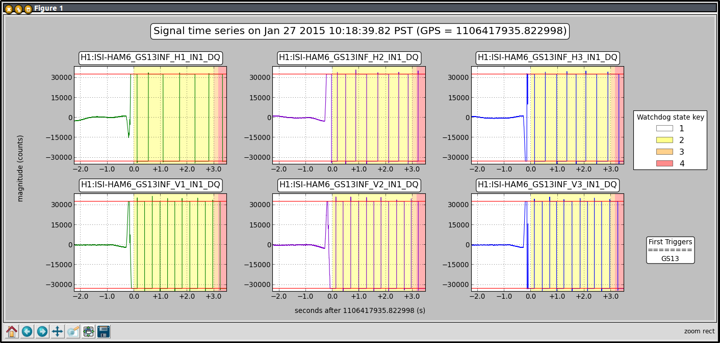
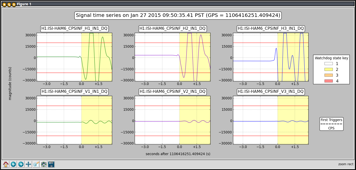
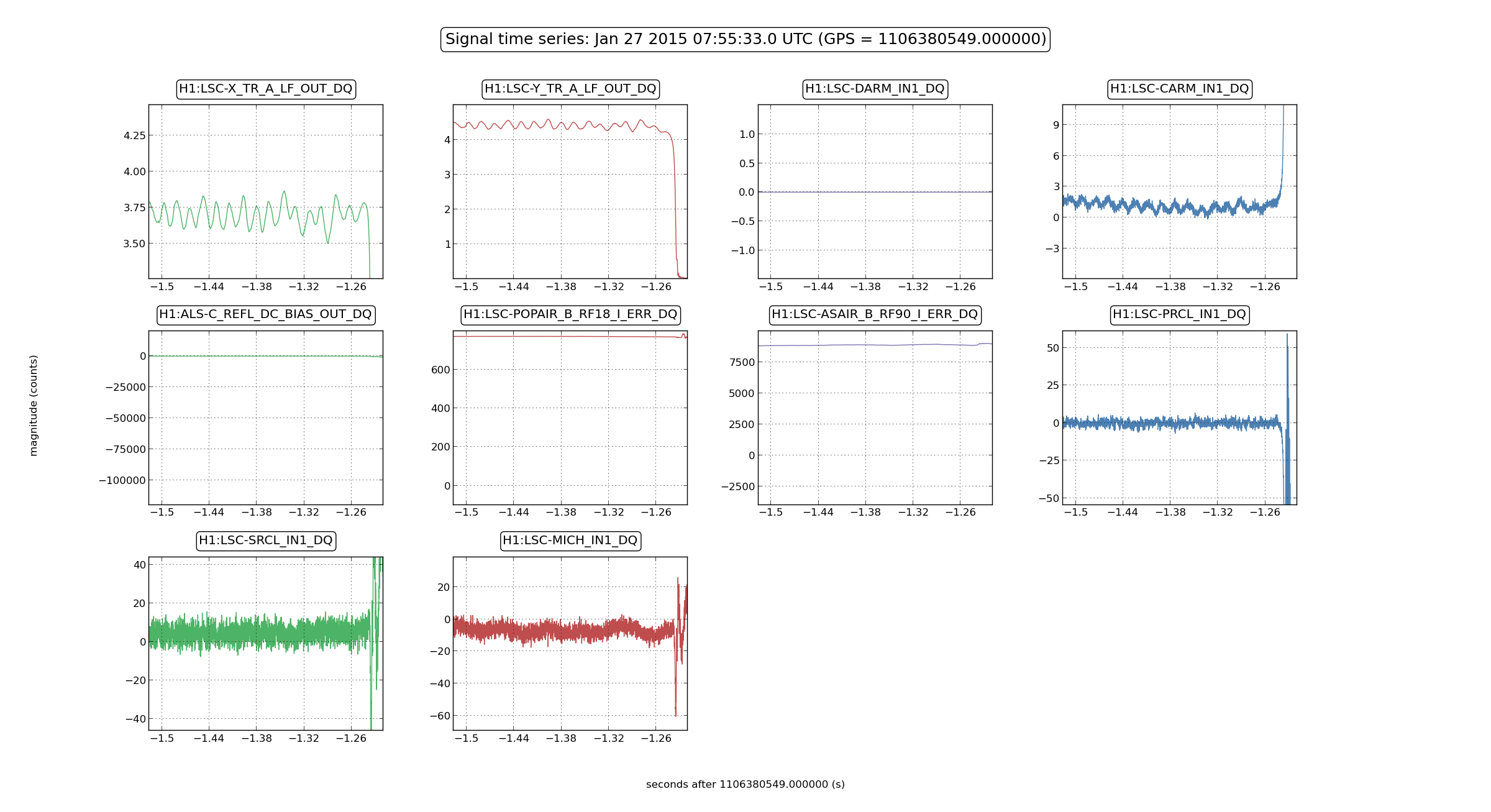
Some lock loss times for today:
Lock losses while transitioning DARM from ALS-DIFF to AS_AIR_45_Q:
06:01:40 UTC (28jan)
06:33:34
07:53:45