stefan.ballmer@LIGO.ORG - posted 18:10, Monday 22 December 2014 - last comment - 09:58, Tuesday 23 December 2014(15792)
DRMI 3f & PRMI (carrier and SB) - all with WFS
Elli, Evan, Thomas, Kiwamu, Stefan

First we made sure we can still run on the 3f diodes with WFS on:
 - After reconnecting REFLAIR_B and removing the beam dump that worked without a hitch - same WFS gains as coded for DRMI.

Next we wanter to check the PRMI - first on SBs:
- We temporarily turned of the WFS and Kiwamu simply kicked out the SRM by misaligning it - the PRMI stayed locked.
- So we simply turned on all WFS with the same gains as DRMI (without the SRCL loops of course). They worked just fine.

Finally we locked the PRMI on the carrier.
- There we had to change the WFS gain for PRC1, PRC2 and MICH. Those 3 loops were then simply closed.
- We had to slightly lower the MICH_P gain, as we were developing an oscillation.
- Kiwamu will post a PRC recycling gain measurement form that data.


The carrier recycling gain was measured to be 45 with the three ASC loops closed in PRMI.
Please forget the previous measured recycling gain (alog 15527).
(Some numbers)
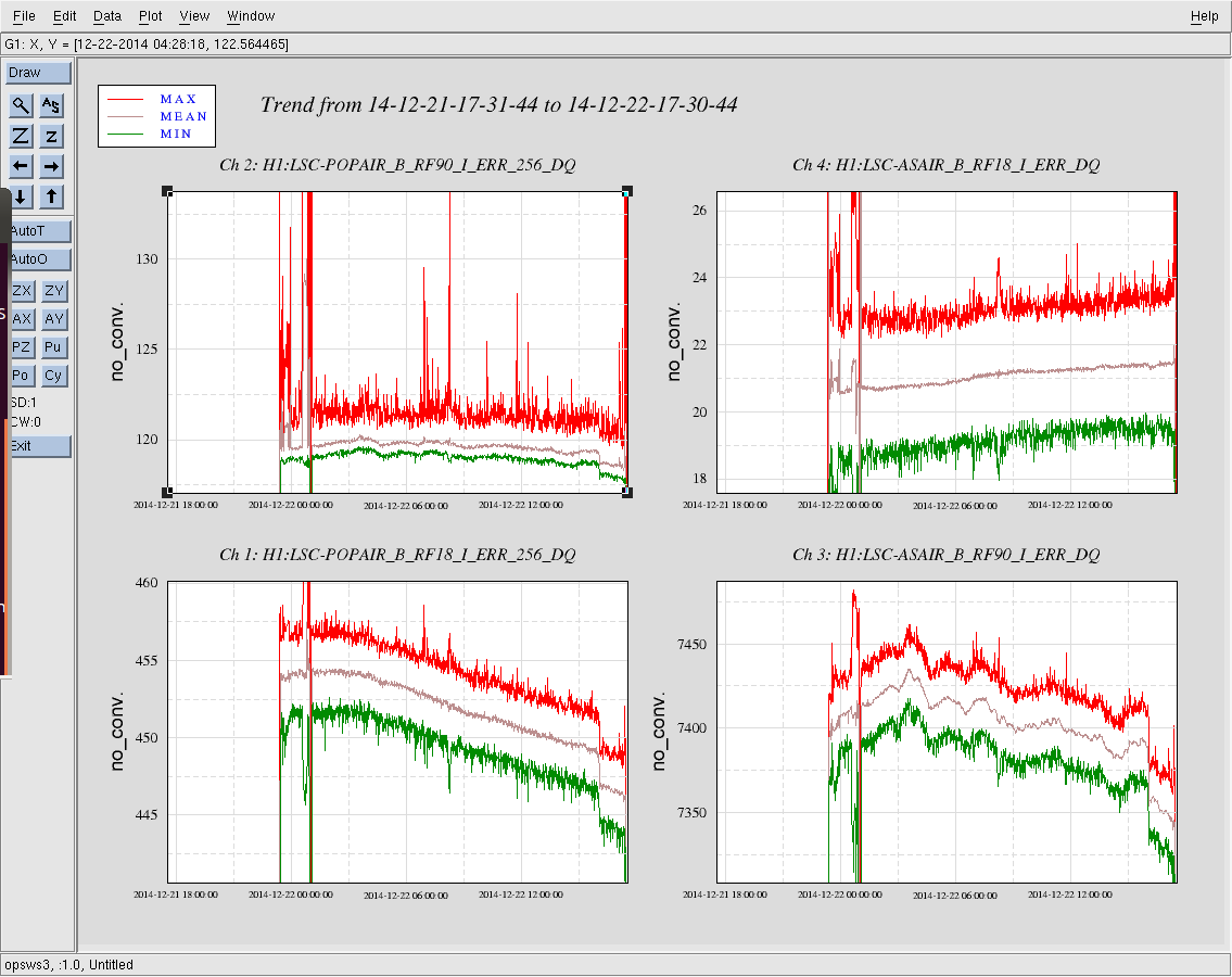
Note that the IMC incident power was at 10 W during the measurement. REFL_LF dropped from a nominal of 83 mW to 6.3 mW when the PRMI was locked. The dark port ASAIR_A_LF stayed at 12000 counts during the lock. We could see a donuts mode at the dark port digital camera.
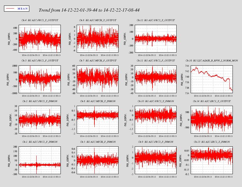
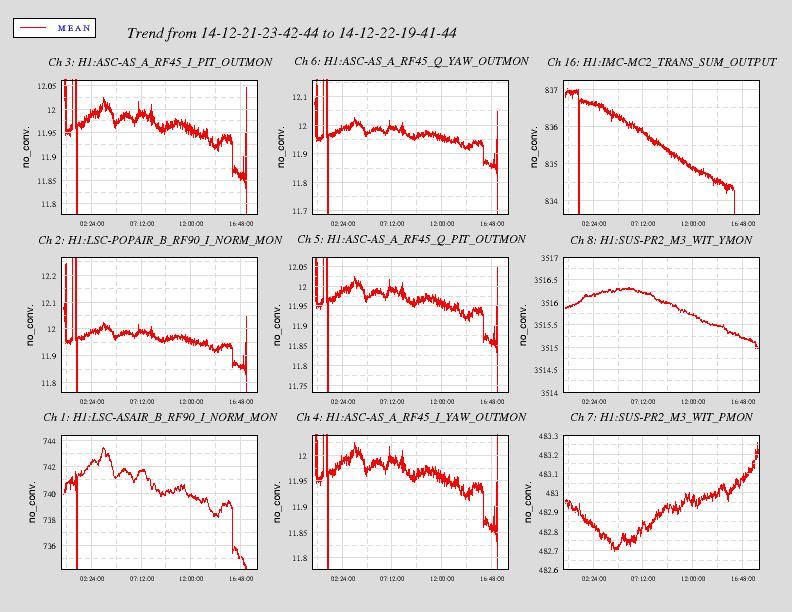
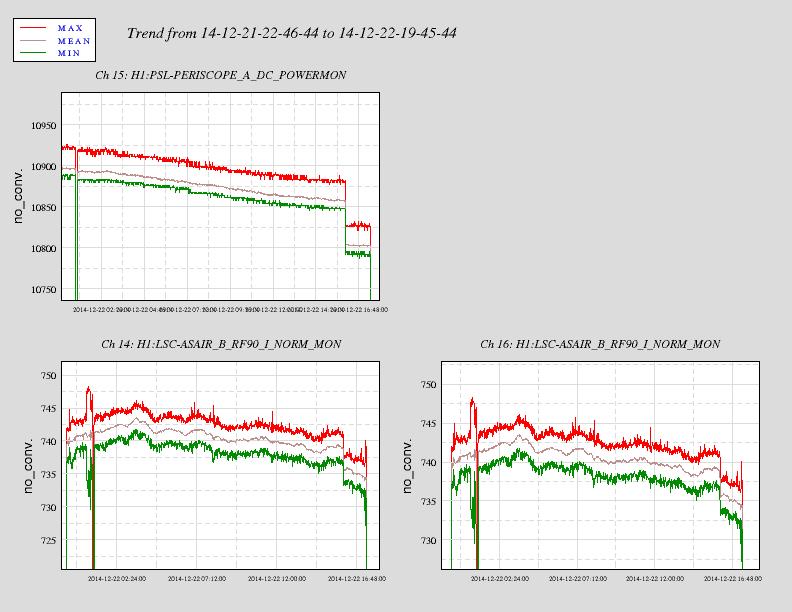
We shut off the ITMX CO2 laser at 20:00:40 in local time (4:00:40 UTC) for tomorrow's HWS project. We are leaving the PRMI locked on the carrier to see what happenes.
To avoid collision between the TCS step and Hugh’s sensor correction test, we have set the the senscor test to start 4.5 hours from now (through the magic of
sleep).Some notes on the PRMI recycling gain measurement (UTC date is 2014-12-23):
01:59:20 – MICH is locked on a dark fringe.
02:00:00 – IMC is unlocked.
Also, the last week’s improvements to the PRMI carrier locking (including ASC improvements) are now implemented in the
LSC_CONFIGSguardian.The lock held for about 8 hours, from about 8 PM to 4 AM local time.