sheila.dwyer@LIGO.ORG - posted 19:46, Thursday 22 January 2015 - last comment - 13:06, Friday 23 January 2015(16220)
TR CARM work today
Evan, Alexa, Elli, Sheila, Rana,
- Evan changed the gain on the END Y TR PD to 20dB, while the X end 1 is still at 0dB (alog 16211)
- We realized that with our better recyling gain, the locking offset and gain we used last night were not sensible. We are not using an offset in sqrt(TRX+TRY) of -1.7, which would put us at 300 pm if the recylcing gain is 30, similiar to the CARM offset that we used before. We also estimated that the calibration into picometers should be changed from 312 to 180. (this is the to_pm FM in TR_CARM)
- Alexa realized that the res G filter to supress 1 Hz noise in ALS DIFF was not on, turning this on reduced the RMS of ALS by about a factor of 10, helping us to stay in the linear range of TR CARM.
- We have been stable in the state PREP_TR CARM for 10 minutes or so. We have been able to turn the gain of the ALS signal down to -11dB on the common mode board, while the TR CARM input was at a gain of 4dB.
- We changed the low frequency boost in LSC-REFL BIAS, we are no longer engaging FM6 (a true integrator with a zero at 1 Hz). We also changed FM5 so it is no longer a true integrator, it now has a pole at 1Hz and is turned on in PREP_TR_CARM. We have also stopped using the lead filter in FM8, we have plenty of phase without it.
- We measured the cross over in ALS COMM to be at 50 Hz, with 45 degrees of phase margin.
We think that we are loosing lock due to some 12-15 Hz noise in CARM which is non stationary. We watched the spectrum of CARM locked on ALS with and without DIFF locked, and saw that the non stationary noise is only there when DIFF is locked. We then looked back at our ALS DIFF design (alog 15025) and decided to reduce the gain by 35%. This has reduced the gain peaking, but we still have nonstationary noise in CARM.
lock loss times: 1:44:20 UTC, 3:01:27 UTC Jan 23rd UTC lock loss durring swept sine excitation 3:55 UTC


The first attachment is of a REFLBIAS transfer function when we had partially transitioned between TRXY and ALS COMM (CMB IN1 Gain was 4, and CMB IN2 gain was -11). When we measured this TF we had not engaged the FM5 boost. Still, this does not look correct ...
The second attachment is of ALS DIFF and CARM spectra. It seems we had some gain peaking in ALS diff, which motivated us to lower the gain as Sheila mentioned. This reduced the peak in CARM, but did not eliminate it.
Here are some more lock loss times for last night:
23/1/15 00:03:03 UTC
23/1/15 01:14:01 UTC
23/1/15 01:43:45 UTC
23/1/15 02:17:01 UTC
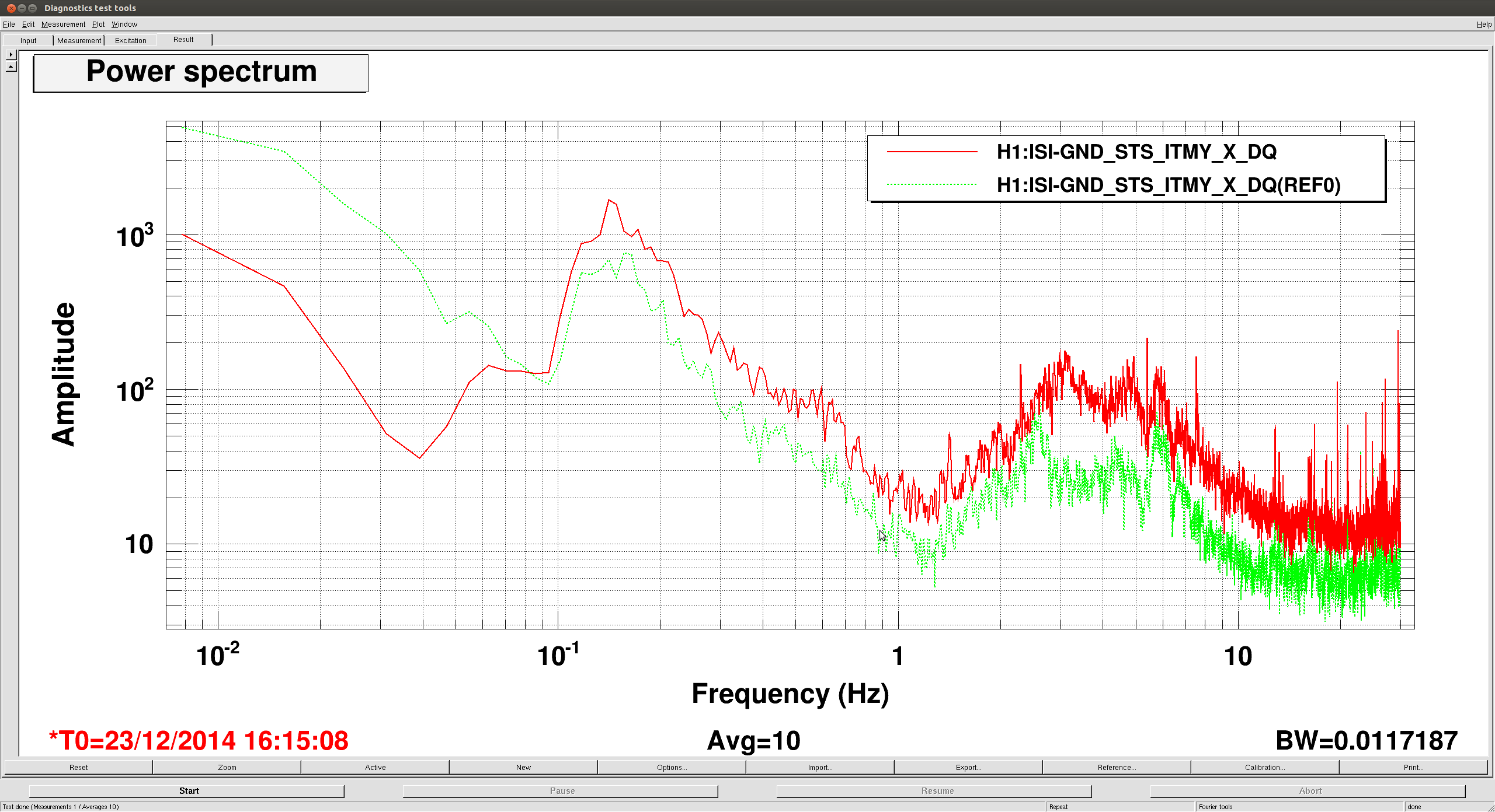
Attached is lockloss plot at 23/1/15 00:03:03 UTC. LSC-REFL_SERVO_IN2GAIN was turned down at 00:03:03 -26 seconds. Lock was lost 26 seconds later. CARM noise dropped once the gain was turned down. Also attached is a power spectrum of CARM signals before and after turning down the gain. REfs 0 and 1 are before, refs 4 and 5 are after. Puzzlingly, the high frequency noise increased after the ALS gain was turned down.
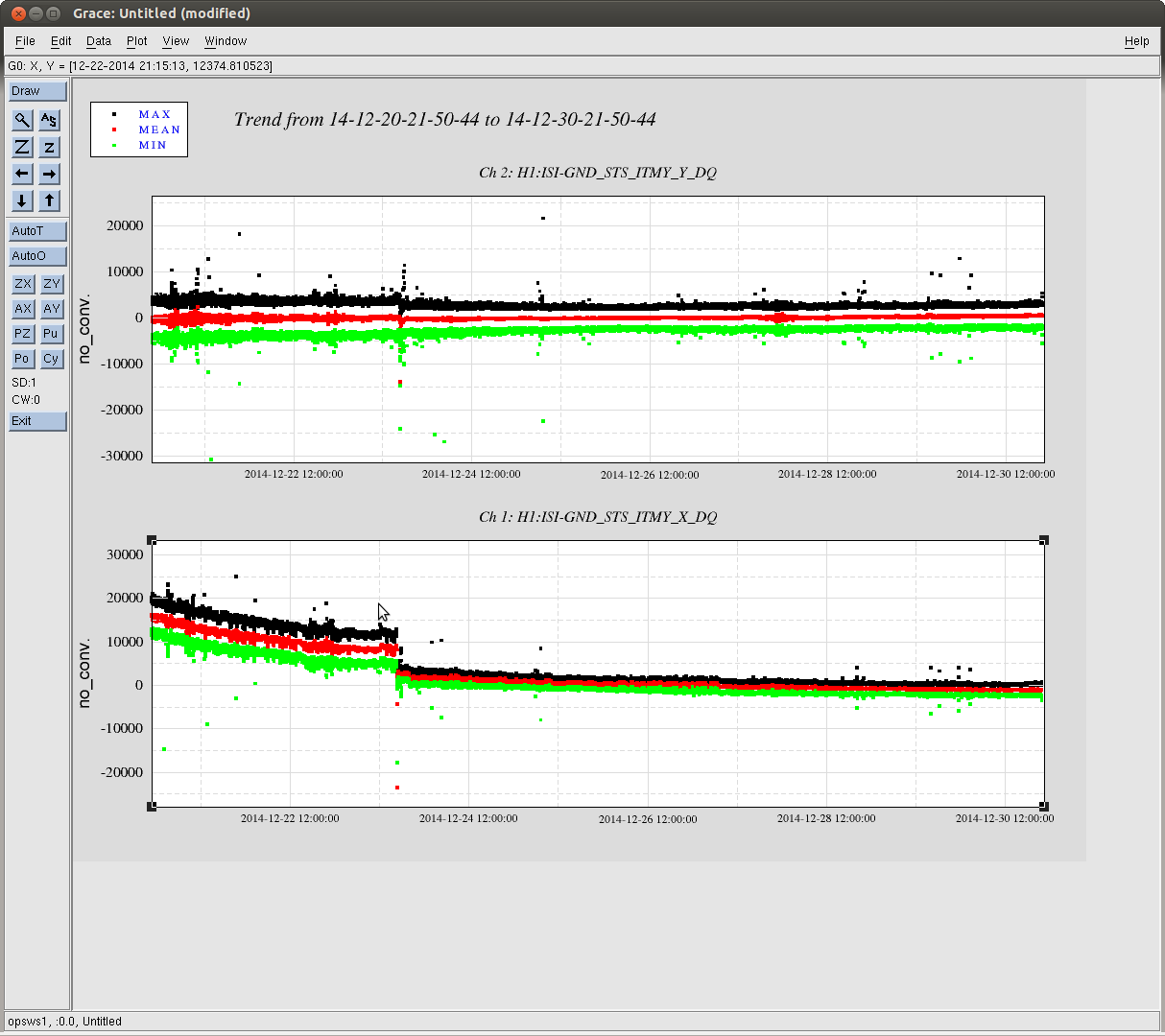
Here are some other lock loss plots from yesterday. The first one shows that the ALS Y glitch caused one of our locklosses, the Y arm transmission went to 0, with the charachteristic glitch in Y REFL CNTRL, as seen in alog 15242 and 15402. We think this was bad luck, and a reminder that these glitches are a problem.
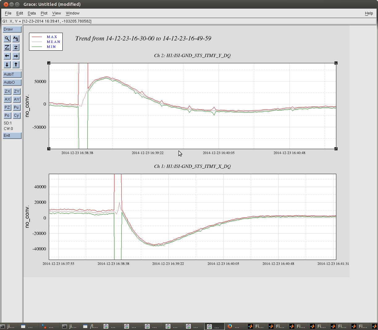
The other lock losses were less conclusive so far, I've attached a plot that shows that as the gain of the ALS path is ramped down on the common mode board we have large glitches in CARM, however the lock survives this and drops a few seconds later.